When Huygens and Mariotte agree Walter Tape University of Alaska, Department of Mathematics 6660, Fairbanks, Alaska 99775-6660, USA (
[email protected]) Received 23 April 2008; accepted 14 May 2008; posted 30 May 2008 (Doc. ID 95368); published 4 September 2008
Edme Mariotte in the seventeenth century attributed halos to tiny ice prisms in the atmosphere. Christiaan Huygens attributed them to tiny spheres or cylinders. The two seemingly incompatible theories largely agree in their predictions for the common halos. This article explains why. © 2008 Optical Society of America OCIS codes: 000.2850, 010.1290, 010.2940.
The modern theory of atmospheric halos has its origins in the seemingly disparate ideas of Edme Mariotte [1] and Christiaan Huygens [2] in the seventeenth century. Both of them attributed halos to the refraction of sunlight in ice particles in the atmosphere, but Mariotte believed the particles to be equilateral triangular prisms, whereas Huygens believed them to be either transparent cylinders having opaque cylindrical cores (Fig. 1), or else transparent spheres having opaque spherical cores. For Huygens the ratio m of the core radius to the particle radius was fixed and played a critical role. Mariotte’s particle model eventually turned out to be right, essentially, and today Huygens’ theory gets short shrift in the halo literature: “Huygens was wrong.” But Huygens’ theory was more sophisticated than Mariotte’s, and Huygens treated more halos than did Mariotte. Moreover, the two theories largely agree in their predictions for the common halos. There is good reason for the agreement and, as a result, Huygens’ powerful conceptual and mathematical insights, which were far beyond anything that Mariotte had done, were eventually incorporated into the Mariotte theory. The purpose of this article is to explain why the theories of Huygens and Mariotte were so closely related. Mariotte himself treated only the 22° halo and the parhelia, but once his ideas are extended, the Huygens and Mariotte theories agree about the predicted location of the sunward edges of most of the common 0003-6935/08/340H85-06$15.00/0 © 2008 Optical Society of America
halos: the 22° and 46° halos, the parhelia, the upper and lower tangent arcs to the 22° halo, and the circumzenith arc. The claimed agreement may already be plausible from Fig. 2. The figure shows the Huygens cylinder and the equivalent Mariotte prism or, rather, wedge [3]. The ray path in the figure is the minimum deviation ray path for sun rays passing through the cylinder, and it is also the minimum deviation ray path for sun rays passing through the prism as the prism rotates about its axis. The sunward edge of the Huygens parhelion would therefore coincide with the sunward edge of the Mariotte parhelion. This same insight extends to other common halos. From Fig. 2 the relation between Huygens and Mariotte is α m ¼ sin ; 2
ð1Þ
where α is the wedge angle, m is the core radius of the cylinder, and the radius of the cylinder itself is 1. Since α ¼ 60° for the Mariotte wedge, then m ¼ 1=2 for the Huygens cylinder. Huygens of course did not have the luxury of knowing α—or even of contemplating it—but he knew the halo radius that he wanted, and he calculated m ¼ 0:48 from the halo radius and from the refractive index of ice. 1.
The parhelia
To flesh out the argument, we first recall how to calculate ray paths or, rather, light points. The light point of a ray is the point on the celestial sphere that the ray would appear to be coming from, if it were to 1 December 2008 / Vol. 47, No. 34 / APPLIED OPTICS
H85
Fig. 1. (a) The Huygens cylinder. (b) End view showing paths of some sun rays through the cylinder. The least deviated ray (for a fixed sun and fixed cylinder) is tangent to the core.
reach the eye of an observer. However, the radius of the celestial sphere is understood to be equal to the refractive index of the medium traversed by the ray. Suppose as in Fig. 3 that a ray is refracted at a boundary between two media having refractive indices n1 and n2 . Then the light points S and R of the incident and refracted rays are on concentric spheres of radii n1 and n2 . Snell’s law [4] then takes the form: The line segment SR is normal to the boundary between the two media and does not penetrate the inner sphere. Thus either of S and R determines the other. This remarkably simple geometric formulation of Snell’s law more than makes up for the awkwardness of having two celestial spheres. Let’s now examine a typical parhelion ray path, first for Mariotte, then for Huygens (Fig. 4). Both men attributed the parhelia to vertically oriented particles—prisms for Mariotte and cylinders for Huygens. Figure 4(a) shows a ray path through one of Mariotte’s prisms, together with line segments N 1 and N 2 normal to the entry and exit faces. Figures 4(b) and 4(c) then show the light points S, R, and H of the entry, internal, and exit rays. As per Snell’s law above, the point S—the sun point— together with N 1 determines R, and then R together with N 2 determines H—the halo point. The halo point is the point on the celestial sphere that the exit
Fig. 3. Geometric formulation of Snell’s law. (a) Incident and refracted rays S and R in media having refractive indices n1 and n2 . The line segment N 1 is normal to the boundary between the two media. (b) Corresponding light points S and R on spheres having radii n1 and n2 and common center O. The vectors SO and RO are in the directions of S and R. Snell’s law is equivalent to requiring that the line segment SR be parallel to N 1 and not penetrate the inner sphere.
ray from the prism would appear to be coming from. Notice that although the entire ray path is shown, only S, N 1 , N 2 , and n were needed to get H. Starting with the light points S, R, and H, we can recover the ray path, since the entry, internal, and exit rays must be in the directions SO, RO, and HO. The light points also determine the wedge, including its wedge angle, orientation, and refractive index. So the “vee”—the configuration of light points—serves as a shorthand for the ray path and the oriented wedge. The Mariotte parhelia form when the prism in Fig. 4 rotates about its axis. The Huygens parhelia form when the entry point of the sun ray varies on the cylinder. In either case the resulting halo point H—in Fig. 4(b) for Mariotte, in Fig. 4(e) for Huygens—traces out the parhelia. For Mariotte all vees have apex angle α, and the closest H to S on the right (say) parhelion is the one whose vee is isosceles [orange in Fig. 5(a)]. For Huygens all vees are isosceles, and the closest H to S is the one whose vee is most acute, that is, has the smallest apex angle [orange in Fig. 5(b)]. If α and m satisfy Eq. (1), then the isosceles vee of Mariotte is the same as the most acute vee of Huygens, and the sunward edge of the Mariotte parhelion coincides with the sunward edge of the Huygens parhelion. The predicted location of the sunward edge is borne out by observations. Although the Huygens and Mariotte theories turn out to predict quite different intensity distributions for the parhelion, they agree that the brightest part of the parhelion should be at the sunward edge. So both theories offered compelling explanations. 2.
Fig. 2. Relation between the Huygens cylinder and the equivalent Mariotte wedge. The ray path—the same in all three diagrams—is the minimum deviation ray path (for fixed sun) through the fixed cylinder, and it is also the minimum deviation ray path through the wedge as the wedge rotates in the plane of the paper. H86
APPLIED OPTICS / Vol. 47, No. 34 / 1 December 2008
Bravais’ law
Light point diagrams like those in Fig. 4 make it relatively easy to calculate the parhelia for any sun elevation Σ. But although the diagrams are just geometric expressions of Snell’s law, neither Huygens nor Mariotte was aware of them. That made the parhelia
Fig. 4. (a) Ray path through a vertical Mariotte prism, seen from above, together with line segments N 1 and N 2 normal to the entry and exit faces. The segments N 1 and N 2 are in the plane of the paper (horizontal), but the ray path here is not. (b) The corresponding vee—the configuration of light points S, R, and H of the entry, internal, and exit rays. The spheres have radii 1 and n, the refractive indices outside and inside the prism. The outer sphere (gray) has been cut away to expose part of the inner sphere. (c) The same vee but seen from above in order to emphasize its relation with the ray path: The vectors SO, RO, and HO are in the directions of the entry, internal, and exit rays. The segments SR and RH are parallel to N 1 and N 2 . Here the points S, R, and H are in the plane of the paper, but O, the common center of the spheres, is not. (d)–(f) Similar but for the Huygens cylinder.
more difficult to calculate for non-zero Σ, since in that case no ray path was planar. Huygens was nevertheless able to make the calculation. He used Bravais’ law, nearly two centuries before Bravais: A normal plane for a ray path is any plane parallel to both the entry and exit normals. Bravais’ law says that the projection of a ray path onto a normal plane obeys Snell’s law if the refractive index n is replaced by n0 ¼
n2 n1
ðBravais refractive indexÞ;
ð2Þ
where n2 ¼
pffiffiffiffiffiffiffiffiffiffiffiffiffiffiffiffiffiffiffiffiffiffiffi n2 − sin2 Σ
n1 ¼ cos Σ
ð3Þ
and where Σ is the angle of inclination of the entry ray to the normal plane. Bravais’ law follows from the geometric form of Snell’s law and Fig. 4 (left or right). The plane N
through S, R, and H—the plane containing the annular region in the figure—is a normal plane. The entry, internal, and exit rays themselves are in the directions SO, RO, and HO, and their projections on N are in the directions SO0 , RO0 , and HO0 , where O0 is the projection of O on N. Thus the points S, R, and H are the light points of the projected rays if the points are regarded as being on spheres centered at O0 , and if the refractive indices are redefined to be equal to the radii of these two spheres. But the radii are just the radii of the inner and outer boundaries of the annular region in the figure, and they are easily found to be n1 and n2 of Eq. (3). The projected rays are therefore behaving as if they were in media having refractive indices n1 and n2 or, equivalently, in media having refractive indices of 1 and n2 =n1 . This is Bravais’ law. Huygens used Bravais’ law first to calculate the parhelia as a function of sun elevation. He then used the parhelion results to calculate the shape of the tangent arcs. 1 December 2008 / Vol. 47, No. 34 / APPLIED OPTICS
H87
Fig. 5. Comparison of the Mariotte and Huygens parhelia. In each case the sun is at S and the (right) parhelion is the red circular arc PT. The sunward edge P of the parhelion is the same for both. The vees shown are those associated with the points P (orange) and T (green). Sun elevation Σ ¼ 30°.
3. The tangent arcs
Already in the 1660’s Huygens realized that the upper and lower tangent arcs consist of rotated parhelia, and he was able to calculate the appearance of the tangent arcs as a function of sun elevation. He was justifiably proud of his insight. Figure 6 shows the idea. The figure happens to be for the Mariotte rather than for the Huygens tangent arcs, but the idea is the same for both. The red curves in the figure come in pairs, each pair being associated with a horizontal direction A. Each pair can be thought of as a pair of rotated parhelia as shown. The sunward boundary (orange curves) of the tangent arcs, which consists of the sunward edge of each rotated parhelion, would be the same for Huygens as for Mariotte, just as the two orange points P in Fig. 5 are the same. The outer boundary (green curves), consisting of the outer edge of each rotated parhelion, would of course be different for Huygens, just as the
two green points T in Fig. 5 are different. The intensity distribution for the tangent arcs would be different in the two theories as well. But it was the sunward boundary, where the halo tended to be bright and well-defined, that was of interest, and there the theories agreed. Figure 6 is for the 22° tangent arcs of Mariotte. For the 46° tangent arcs of Mariotte the wedge angle α would have to be changed from 60° to 90°. For those of Huygens pffiffiffithe parameter m would be changed from 1=2 to 1= 2, by Eq. (1). Then the sunward boundaries would be the same for the Huygens and Mariotte 46° tangent arcs. The modern explanation for the circumzenith arc is due to Bravais [5] in 1847, and in the eighteenth century the circumzenith arc was often considered, incorrectly, to be the upper 46° tangent arc. That meant that Huygens and Mariotte agreed on the (sunward boundary of) the circumzenith arc.
Fig. 6. Illustrating that the upper and lower tangent arcs consist of rotated parhelia. (a) Upper and lower tangent arcs arising in the Mariotte prism. The two heavy red curves are the portions of the tangent arcs that arise in prisms whose axes point in the horizontal direction A. (b) The same two red curves, but emphasizing that they are rotated parhelia. Before rotation, these two parhelia would look like those in Fig. 5(a). But S in that figure is not the same as S here; the angular distance between S and the zenith in Fig. 5(a) is the same as that between S and A here. H88
APPLIED OPTICS / Vol. 47, No. 34 / 1 December 2008
4. The circular halos
In Mariotte’s theory the 22° circular halo arises in randomly oriented prisms, whereas in Huygens’ theory it arises in transparent spheres having opaque spherical cores. Each halo is an annular region on the celestial sphere, with the 22° halo of Huygens larger than that of Mariotte. The inner (circular) boundaries of the two halos, however, are the same, if, of course, Eq. (1) is satisfied, that is, if m ¼ 1=2 (α ¼ 60°). The details are omitted. Although the two 22° halos share the same inner boundary, the 22° halo of Huygens is abstractly much simpler than that of Mariotte. If one draws a typical ray path through a Huygens sphere, one finds that the corresponding vee is isosceles and central, the latter meaning that the plane of the vee passes through the center of the celestial sphere. Each point of the Huygens 22° halo is therefore the halo point of a unique vee. (Equivalently, each point of the halo corresponds to a unique ray path through the Huygens sphere.) By contrast, a typical point on the Mariotte 22° halo corresponds to infinitely many vees. (The points on the inner and outer boundaries of the halo are exceptions.) The Huygens 22° halo consists of rotated parhelia as shown in Fig. 7. The parhelia are arcs of great circles, that is, in each case the unrotated parhelion is as if the sun were on the horizon. All of the preceding applies also to the Mariotte pffiffiffi and Huygens 46° halos, but with m ¼ 1= 2 and α ¼ 90°. 5. The 120° parhelia
Huygens failed when he came to the two “posterior parhelia”—what we would now call the 120° parhelia. He tried to explain them using his vertical cylinders and the same sort of ray path that Descartes had used successfully for the rainbow. The parhelia that Huygens calculated were too close together to fit the best available observational data, namely, the data from the 1629 Rome display [6]. Rather than blaming his theory, Huygens blamed the data. And why not, given the success of his theory in treating
the other common halos? But the data turned out eventually to be correct. 6.
The eighteenth century verdict
How did the theories of Mariotte and Huygens fare against each other? Mariotte had presented his halo theory to the French Academy of Sciences in 1679 and then published it two years later. Although it was republished in his Oeuvres [1] of 1717, and again in 1740, it apparently did not become well known until much later. Its only early adherent, as far as I know, was Cassini [7]. The only halo work of Huygens that he himself published is the 1667 Relation d’une Observation [8], which was only an outline of his theory. Although most of Huygens’ halo work was done in the 1660’s, a detailed exposition of it was not available until the Opuscula Postuma [9] appeared in 1703, after his death. In the ensuing century Huygens’ theory seems to have been generally accepted, though we do not have many sources to go on. A sample of opinion: Smith’s Opticks [10] of 1738 contained a 29-page English translation of the Opuscula Postuma but never mentioned Mariotte. Musschenbroek [11] in 1748 tried to present some of Huygens’ ideas but seems not to have understood them fully. Weidler [12] in 1738 offered his own ideas about halo formation and tried to refute those of Huygens. Joseph Priestley [13] is our best source. In a thoughtful appraisal of halo science as of 1772, Priestley made it clear that the last word had not yet been said. Here is his assessment of Huygens: The most considerable of all the theories respecting halo’s, and that which has met with the most favourable and the longest reception, is that of M. Huygens. Sir Isaac Newton mentions it with respect, and Dr. Smith, in his Complete system of optics, does not so much as hint at any other. On this account, my reader will expect a fuller account of it than I myself should, otherwise, think it deserved.
Priestley went on to give a balanced account of the Huygens theory. In the following quote he paraphrases Huygens’ own abstract justification for the seemingly outlandish ice cylinders and spheres: …if we can conceive any kind of bodies in the atmosphere, which, according to the known laws of opticks, will, either by means of reflexion or refraction, produce the appearance in question, when nothing else can be found that will do it, we must acquiesce in the hypothesis, and suppose such bodies to exist, even though we cannot give a satisfactory account of their generation.
As for Mariotte, Priestley says Fig. 7. The 22° circular halo of Huygens. It is an annular region centered at the sun S. Each “spoke” of the halo is a rotated Huygens parhelion, one of which (the heavy curve) is shown in more detail at the right. The two vees shown are for minimum and maximum deviation for the Huygens sphere.
M. Mariotte then proceeds to explain the larger corona’s, namely those that are about 45 degrees in diameter, and for this purpose he has recourse to equiangular prisms of ice, in a certain position with 1 December 2008 / Vol. 47, No. 34 / APPLIED OPTICS
H89
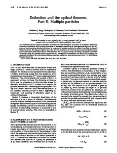
same as Fig. 2, showing the relation between the Huygens and Mariotte halo-makers. Referring to his diagram, Huygens explained halo colors, saying that they arose just as in the triangular glass prism indicated by the tangents CA drawn to the cylinder at the points where the ray DA enters or exits. The prism would of course have been the Mariotte halo-maker. References and Notes
Fig. 8. Diagram of Huygens [8] showing ray paths through his halo-making cylinder. Huygens recognized that the triangular prism ACA was closely related to his cylinder, but it apparently did not occur to him that such prisms—not the cylinders—might be making the halos. (Courtesy Leiden University Library).
respect to the sun; and he takes pains to trace the progress of the rays of light for this purpose; but this hypothesis is so improbable, that I shall easily be excused for not following him in his investigation.
Modern jaws may drop at Priestley’s appraisal of Mariotte, but we should not be so surprised that the Mariotte theory offered little challenge to Huygens in the eighteenth century. Although, as we have seen, the two theories were close in their predictions for the common halos, this was not fully appreciated at the time, and in fact Mariotte’s theory had been applied only to the 22° halo and to the parhelia, and indeed only to the parhelia with the sun on the horizon. Moreover, nobody had gotten a good look at a prismatic columnar ice crystal under the microscope, so that Mariotte’s ice particles might have seemed as exotic as those of Huygens. Priestley died in 1804. Not long after, Young [14] and Venturi [15] began to revive and extend Mariotte’s theory, making it a lethal competitor with that of Huygens. Priestley never saw how prescient had been his qualification “when nothing else can be found that will do it.” 7. Huygens came so close
Huygens very nearly stumbled on the Mariotte prism model for his halo-making particles. The diagram in Fig. 8, reproduced from Huygens [8], is nearly the
H90
APPLIED OPTICS / Vol. 47, No. 34 / 1 December 2008
1. E. Mariotte, Oeuvres de Mr. Mariotte, Vol. 1, pp. 272–281 (Pierre Vander, 1717). 2. C. Huygens, Oeuvres Complètes de Christiaan Huygens, Vol. 17 (Martinus Nijhoff, 1932). Available at http://gallica.bnf.fr/. 3. We often refer to Mariotte’s halo-maker as a prism, but we usually ignore all but the entry and exit faces, in which case the “prism” is really an idealized wedge having only two faces, which are half-planes. 4. W. Tape and J. Moilanen, Atmospheric Halos and the Search for Angle x (American Geophysical Union, 2006). 5. A. Bravais, “Mémoire sur les halos et les phénomènes optiques qui les accompagnent,” Journal de l’École Royale Polytechnique, 31 Cahier 18, 1–280 (1847). 6. W. Tape, E. Seidenfaden, and G. P. Können, “The legendary Rome halo displays,” Appl. Opt. 47, H72–H84 (2008). 7. Cassini, “Observation de deux Paraselenes, & d’un Arc-enCiel dans le crepuscule,” Histoire de l’Académie royale des sciences avec les mémoires de mathématique et physique 10, 400–402 (1730). The article is originally from 1693. 8. C. Huygens, Relation d’une Observation faite a la Bibliotheque du Roy, à Paris, le 12 May 1667… (Jean Cusson, 1667). An English version is in [16]. 9. C. Huygens, B. de Volder, and B. Fullenius, Christiani Hugenii Zelemii, dum viveret, Toparchae. Opuscula Postuma,… (Apud Cornelium Boutesteyn, 1703). Available at http://fermi.imss.fi. it/. An English version is in [10]. 10. R. Smith, A Compleat System of Opticks in Four Books… (Cornelius Crownfield, Cambridge, 1738). The discussion of halos is in Chap. 11 of Book 2, pp. 199–238. 11. P. Musschenbroek, Institutiones Physicae Conscriptae in Usus Academicos (Apud S. Luchtmans et filium, 1748). The halo discussion is pp 677–689 and Table XXVIII. 12. T. Stack, “An Account of a Tract Intituled, Jo. Friderici Weidleri Commentatio de Parheliis Mense Januario Anni 1736…,” Phil. Trans. R. Soc. 41, 459–465 (1739–1741). Available at http://www.jstor.org/stable/i206906. 13. J. Priestley, The History and Present State of Discoveries Relating to Vision, Light and Colours (J. Johnson, 1772). Halos are treated on pp. 596–630 and in Figs. 141–148. 14. T. Young, A Course of Lectures on Natural Philosophy and the Mechanical Arts (J. Johnson, 1807). Vol. 1, pp. 443–444 and Plate XXIX, and Vol. 2, pp. 303–308. 15. G. Venturi, Commentarj sopra la Storie e le Teorie dell’ Ottica (Pe’ fratelli Masi, 1814). 16. C. Huygens, “An Account of the Observation, Made by the Philosophical Academy at Paris, May 12 1667 …” Phil. Trans. R. Soc. 5, 1065–1074 (1670). Available at http://www.jstor.org/ stable/i206870.