REVIEW OF SCIENTIFIC INSTRUMENTS
VOLUME 70, NUMBER 10
OCTOBER 1999
Very high sensitivity ac capacitance bridge for the dielectric study of molecular solids at low temperatures S. Pilla, J. A. Hamida, and N. S. Sullivan Department of Physics, University of Florida, Gainesville, Florida 32611
共Received 10 March 1999; accepted for publication 24 June 1999兲 An ac capacitance bridge with excellent stability and two parts per billion resolution in the real part of the dielectric constant at temperatures ranging from 4.2 to 80 K and in the audio frequency range 共0.2–20 kHz兲 is reported. The method uses commercially available components as well as few homemade cables and capacitors. Construction details and data on the resolution are presented. © 1999 American Institute of Physics. 关S0034-6748共99兲02810-5兴
the loss part has a 2⫻10⫺7 resolution similar to that reported elsewhere.6,9 The novel feature of the bridge design is the use of a carefully machined dual capacitance cell with cylindrical capacitors machined into a single block of OFHC copper. One capacitor serves as the sample cell and the second as a reference cell. With the careful matching of the capacitances, spurious temperature dependent effects due to thermal expansion and changes in the electrical conductivity of the cell are annulled automatically to a high degree. In addition, this technique allows us to determine the background dielectric response to a high accuracy over a wide temperature range 共4.2–80 K兲. This ability is critical for detecting small dielectric response in field cooling cycles and nonlinear susceptibilities in molecular glasses and related systems.13
I. INTRODUCTION
Low frequency dielectric measurements are very important in the study of cryocrystals and molecular glasses, as studies of the slow relaxation processes in these systems provide information about their collective interactions. In principle, the dielectric susceptibility can be a very sensitive probe for studying such slow processes, while other techniques such as nuclear magnetic resonance 共NMR兲, heat capacity, and thermal conductivity measurements lack the required sensitivity. In almost all cases, however, the change in the dielectric constant with external influence such as temperature, dc electric and magnetic fields, etc. is very small, requiring a high sensitivity, high resolution apparatus with long time stability 共of the order of few hours兲 and good temperature control. The two principal methods for detecting changes in the dielectric constant are to incorporate a capacitor as a frequency determining element in an oscillator1–3 or to use a capacitance bridge4,5 for comparing the capacitor with a reference capacitor. An excellent review article by Adams6 discusses various techniques involved in achieving the highest sensitivity in dielectric susceptibility measurements. There has been tremendous improvement in the highest sensitivity achieved over the last two or three decades, though the technique is fundamentally the same throughout. During the 1970s the highest sensitivity reported was7,8 10⫺6 and during the 1980s it was9 10⫺7 . With the help of better lock-in detection as well as signal averaging techniques, a few low temperature groups10,11 have recently reported a sensitivity of 10⫺8 . A recent progress report by Donnelly’s group12 shows that work is underway to try to achieve a sensitivity of 10⫺10 with the help of low temperature preamplifiers for the study of dielectric behavior of very small samples at mK temperatures. However, up to the present time the best sensitivity reported is only 10⫺8 . In this work, we report an ac capacitance bridge developed for the dielectric study of bulk samples at temperatures ranging from liquid He temperatures up to liquid nitrogen temperatures. We focus here mainly on the constructional details of the sample cells and low noise, low capacitance, guarded cables, which we show have been able to enhance the resolution by at least an order of magnitude to 2⫻10⫺9 in the real part of the dielectric constant in the entire temperature range while 0034-6748/99/70(10)/4055/4/$15.00
II. BRIDGE CIRCUIT
The block diagram and the equivalent circuit diagram are shown in Figs. 1 and 2. An input voltage V i of frequency is applied across an inductance 共ratio transformer兲 of 1 H which is in parallel with a reference capacitor C 0 and an unknown capacitor C x . A null reading is obtained at the synchronous detector such as a lock-in amplifier, by adjusting the tap of the ratio transformer and the decade resistor R b1 . At balance V 0 is zero resulting Cx x , ⫽ C 0 1⫺x
共1兲
where x is the ratio transformer setting. The change in the loss angle ␦ is given by ⌬ 共 tan ␦ 兲 ⫽2 共 C 0 ⫹C ⬘0 兲 ⌬R,
共2兲
where C ⬘0 is the stray capacitance of the input leads. For a cylindrical capacitor of length L, inner conductor radius a, outer conductor radius b, and filled with a material of dielectric constant ⑀, C x⫽
2 ⑀ 0L ⑀ . ln共 b/a 兲
共3兲
If both C 0 and C x are two cylindrical cells made out of the same materials, have very close geometrical capaci4055
© 1999 American Institute of Physics
4056
Rev. Sci. Instrum., Vol. 70, No. 10, October 1999
Pilla, Hamida, and Sullivan
FIG. 1. AC capacitance bridge. 共a兲 Ultralow distortion 1 mHz to 200 kHz function generator 共Stanford Research Systems Model DS360兲, 共b兲 isolation transformer 共TEGAM Model ST-248A兲, 共c兲 0.05–20 kHz 7 decade 共see Ref. 14兲 ratio transformer 共TEGAM Model PRT73兲, 共d兲 100 ⍀ potentiometer, 共e兲 gain of 1 buffer amplifier, 共f兲 11,111.1 ⍀ with 0.01 ⍀/step decade resistor 共QuadTech Decade Resistor Model 1433-20兲, 共g兲 gain of ten voltage preamplifier 共Stanford Research Systems Model SR550兲, 共h兲 lock-in amplifier 共Stanford Research Systems Model SR510兲.
tances, are maintained at the same temperature, and C x is filled with a material of unknown dielectric constant while C 0 has vacuum, we have f ⑀⫽
x , 1⫺x
共4兲
where f is a small correction factor due to differences in the geometrical capacitance of the cells. This factor can be obtained when both the cells are empty, i.e., f ⫽x 0 /(1⫺x 0 ). Detailed analysis of the realistic circuit 共Fig. 1兲 shows that in situations where the highest possible resolution is desirable, C 3 should be as small as possible and C 4 ⫽C 5 . The key elements in the circuit are the precision ratio trans-
FIG. 2. Equivalent circuit diagram of the ac capacitance bridge. R t : resistance of the ratio transformer, R r : resistance of the tap, R b1 , R b2 : variable resistors for balancing the dielectric loss, R 0 , R x and C 0 , C x are inside the cryostat.
FIG. 3. Low capacitance triaxial cable design. 共a兲 High vacuum BNC post, 共b兲 stainless steal 共SS兲 wire 共see Ref. 15兲 loaded under tension (⬃230 gwt), 共c兲 small copper disc soldered to the SS wire, 共d兲 nylon disc, 共e兲 6 mm i.d. SS tube, 共f兲 insulated copper shim foil which is the outer conductor in a triax, 共g兲 very thin (⬃0.2 mm) wall copper end cap with the open end soldered to the SS tube, 共h兲 1 mm diameter copper post, 共i兲 STYCAST 2850FT seal, 共j兲 small coil of the SS wire to reduce thermal stress.
former and the two isolation transformers. For the success of the technique, two coaxial lines, one for each of the input terminals of the capacitors, neither of which is grounded, is crucial. In a typical arrangement where both the cells are at low temperatures, these leads can be as long as 1.5 m. These distributed capacitances not only influence Eq. 共2兲 but also reduce the signal to noise ratio. In general the changes in the lead capacitances C 4 , C 5 , and C 3 with the change in liquid He level in the Dewar will lower the long time stability of the bridge. These problems of distributed capacitances, vibration noise in the leads, condensation of moisture on the leads outside the dewar are addressed in the present design. III. LOW CAPACITANCE CABLE DESIGN
As discussed above, the most stringent requirements for achieving very high sensitivity and excellent stability of the capacitance bridge are, a highly stable reference capacitor and small lead capacitances. Most of the commercially available coaxial cables have about 1 pF/cm resulting in ⬃150 pF for a typical cable 1.5 m long. We designed a low capacitance triaxial cable 共C 4 and C 5 兲 to significantly reduce these capacitances 共Fig. 3兲. By maintaining a good vacuum we achieved a capacitance of only 25 pF for a 1.5 m long lead. The middle conductor is driven by a low noise buffer amplifier 共gain A⫽1兲 to maintain it’s potential close to that of the inner conductor thereby further reducing the noise induced by this distributed capacitance. The outer most conductor is grounded so that the load seen by the buffer amplifier is also stable. The cable used for output lead 共i.e., C 3 which is common to both the cells兲 is also of a similar design except that it does not have a third conductor and a buffer amplifier because when both cells are balanced, this lead will be carrying a signal of a few nanovolts only. By using a 12.5 mm inner diameter stainless steal tube for C 3 , we achieved a capacitance of 20 pF 共including the connector capacitance兲 for a 1.5 m long cable. To reduce the noise pick up by vibrations, a tension of 230 g weight is maintained in the stain-
Rev. Sci. Instrum., Vol. 70, No. 10, October 1999
FIG. 4. Sample cell design. 共a兲 To low capacitance lead, 共b兲 STYCAST 2850FT seal, 共c兲 sample fill line, 共d兲 gap⬎0.5 mm, 共e兲 Ge thermometer, 共f兲 outer conductor 共gold plated OFHC copper兲, 共g兲 1 mm gap, 共h兲 inner conductor 共gold plated OFHC copper兲, 共i兲 eight segment wire wound resistor wrapped on a gold plated copper rod, 共j兲 0.2 mm thick, 3 mm long lip 共Or1, Or2, Or3兲 three 1 mm thick STYCAST 2850FT O-rings. Or2 is the spacer grounded to within 50 m accuracy. Inner conductor diameter: 2.5 cm, inside length between top and bottom STYCAST spacers: 10 cm.
less steel wires.15 A lock-in preamplifier is placed at the top of the Dewar where the above lead ends. ‘‘Hand Formable’’ Cu cables16 made as short as possible, with insulated Cu shim foil as the outer conductor in a triax, are used for connecting the input leads to the buffer amplifiers, isolation transformers, etc. Copper braided cables are unsuitable because one can induce large capacitance changes by accidentally flexing them. By judiciously placing heat reflectors in the neck of the Dewar, moisture condensation problems were taken care off. We observed no condensation on top of the Dewar even when the cell temperature is as high as 100 K and the Dewar is filled to the brim with liquid He. Vacuum in the lead cables further helped in reducing the temperature fluctuations due to changes in the liquid He level. All three leads were connected at the top of the Dewar 共before they are connected to the vacuum pump兲 so that same vacuum is maintained in all three of them even if there were any leaks in the leads to the gaseous He in the vacuum cans which isolate the cells from the liquid He bath. To further reduce the effects of the building vibrations, vacuum pump noise, etc., the entire Dewar assembly is placed on a 10 ton concrete pad which is well isolated from the floor. IV. SAMPLE CELL DESIGN
Figure 4 shows the design used for the capacitance cells 共only one cell is shown兲. The sample cell and the reference cell are machined out of the same OFHC block and are gold plated to prevent oxidation. Either cell could be used as a reference cell and their geometrical capacitances 共160 pF兲 differ by less than 0.1%. Each cell is a 10 cm long cylindrical shell with 1 mm gap, and 2.5 cm inner cylinder diameter. A ratio of 100 to 1 between length and gap provides good electric field homogeneity. Outer cylinders form one single copper block so that both cells can be maintained at the same temperature. In addition, this common outer conductor which usually carries a signal of few nanovolts at null detection,
AC capacitance bridge
4057
shields the inner conductors which carry large input signals from the nearby ground planes, thereby reducing the ground noise pickup. These cells are sealed with STYCAST 2850FT epoxy resin. It is crucial that the copper lip sandwiched between the STYCAST O-rings be as thin as possible (⬃0.2 mm) and at least 3–4 mm long so that the lip can bend as the STYCAST contracts with temperature. It is also important that an adequate gap 共at least 0.5 mm兲 be left between the innermost O-ring and the copper block 共see figure兲. We made STYCAST O-rings by pouring fresh STYCAST with catalyst 24LV into a teflon mold and curing it for more than 24 h. The two O-rings which are used as spacers are in particular very crucial for the homogeneity 共the cylinders need to be concentric兲 of the electric field. We were able to match the diameter and thickness 共1 mm兲 to within 50 m by using fine emery to grind the O-rings. The entire cell block is placed on a nylon platform and suspended from the top flange of the vacuum can with the help of four nylon rods. Care has been taken to ensure that no part of the STYCAST touches other solid surfaces. A 1 mm i.d., 30% cupronickel alloy tube with a wire wound heater around it is connected to each cell separately for admitting the sample gases. Vacuum jackets separate these sample fill lines from the liquid He bath. The same STYCAST epoxy resin is used to seal these tubes at the cell end as well as electrically isolate them from the cells. To reduce the strain on these seals with thermal contraction, the tubes are coiled into a two-turn spring before connection to the cells. A separate heater segment may be used for heating this spring. The capacitor cells designed as above are tested to withstand pressure differences up to 150 kPa absolute. The heaters at the center of each cell are divided into 8 segments so that while preparing the sample one can apply differential heating and cooling from the bottom of the cell. Apiezon-N grease is used for good thermal contact between heaters and the cells. These cells are separated from the liquid He bath by two vacuum cans. An additional wire wound resister on the outer wall of the inner can is used for temperature control of the entire cell assembly up to 100 K. V. RESULTS AND DISCUSSION
A homemade current controller with a thermometer anchored to the inside wall of the inner can in a negative feedback loop, is used as the temperature controller. Two additional thermometers located in the wells of the central conductors of the cells are used to monitor the temperature homogeneity. The heaters in the cells are unsuitable for sensitive measurements because the leakage currents can induce large transient electric fields as well as undermine the sensitivity of the instrument. When not in use these eight segments are bunched together at the top of the Dewar, disconnected from the power supply, and left to float electrically. A 4 He pressure of a few hundred Pa in the inner can is sufficient to provide the required thermal contact between the cells and the heater. Using this inner vacuum can with He gas as the heat exchanger is most crucial for long time temperature stability of such large capacitor cells. The separation of the cells from the grounded vacuum can walls is more
4058
Rev. Sci. Instrum., Vol. 70, No. 10, October 1999
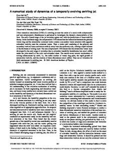
FIG. 5. Lock-in output at high dynamic reserve and 0.1 s time constant for various frequencies. For output 共a兲, 共b兲, and 共c兲 the lock-in sensitivity is 500 nV while 1 V for output 共d兲.
than 2.5 cm there by reducing C 3 (⬃20 pF). With this arrangement, we are able to screen all external electric field fluctuations and gain long time stability of the instrument. Figure 5 shows the lock-in output at a few representative frequencies when both cells are empty. The jump in the output voltage 共in phase兲 corresponds to a change of 1⫻10⫺7 in x for a 5V pp input voltage across each cell. The jump in the out-of-phase output voltage corresponds to a 0.1 ⍀ change in R b1 . These data clearly demonstrate the long time stability and excellent resolution 共two parts per billion resolution before signal averaging兲 of the apparatus. Figure 6 shows the background data 共i.e., the correction factor f 兲 when both cells are empty. Except for a small kink at ⬃15 K, the background is featureless up to ⬃80 K. From these data we note that the cell capacitances are matched to within 0.068%. In summary, we report the realization of an ultrahigh sensitivity susceptometer based on the well-known ac capacitance bridge technique which has a long time stability of the order of few hours. The resolution achieved was two parts per billion for the real part of the dielectric constant. This apparatus is most useful for the study of the orientational behavior of condensable gases such as N2, O2, CO, Cl2, etc. at low temperatures ranging from 4.2 to 80 K. With little modification one may use it at higher temperatures also but with reduced sensitivity.
Pilla, Hamida, and Sullivan
FIG. 6. Background data when both the cells are empty. Excitation potential is 5V pp at 1 kHz. There is no observable hysteresis in the background with thermal cycling.
ACKNOWLEDGMENTS
Stimulating discussions with Yasu Takano are acknowledged. The authors thank J. Xia for his help and gratefully acknowledge the support of L. Phelps, P. Strider, G. Labbe, B. Lothrop, D. Roscigno, W. Malphurs, M. Link, E. Storch, T. Melton, S. Griffin, and R. Fowler. This work is supported by a grant from the National Science Foundation No. DMR962356. 1
M. Chester, S. C. Choudhery, B. K. Jones, and D. Williams, Rev. Sci. Instrum. 39, 719 共1968兲. 2 J. F. Jarvis, D. Ramm, and H. Meyer, Phys. Rev. 170, 320 共1968兲. 3 C. T. Van Degrift, Rev. Sci. Instrum. 46, 599 共1975兲. 4 G. C. Straty and E. D. Adams, Rev. Sci. Instrum. 40, 1393 共1969兲. 5 J. R. Gonano and E. D. Adams, Rev. Sci. Instrum. 41, 716 共1970兲. 6 E. D. Adams, Rev. Sci. Instrum. 64, 601 共1993兲. 7 J. H. Constable, C. F. Clark, and J. R. Gaines, J. Low Temp. Phys. 21, 599 共1975兲. 8 B. A. Wallace, Jr. and H. Meyer, J. Low Temp. Phys. 15, 297 共1974兲. 9 M. C. Foote and A. C. Anderson, Rev. Sci. Instrum. 58, 130 共1987兲. 10 P. Strehlow, C. Enss, and S. Hunklinger, Phys. Rev. Lett. 80, 5361 共1998兲. 11 J. J. Niemela and R. J. Donnelly, J. Low Temp. Phys. 98, 1 共1995兲. 12 Tamar More, J. J. Niemela, and R. J. Donnelly, J. Low Temp. Phys. 98, 441 共1998兲. 13 S. Pilla, J. A. Hamida, K. A. Muttalib, and N. S. Sullivan, Phys. Lett. 256, 75 共1999兲. 14 8 decades for frequencies less than 1 kHz. 15 Cooner Wire Co, 9265-T Owensmouth Ave. Chatsworth, CA 91311. 16 Micro-Coax, 206 Jones Blvd., Pottstown, PA 19464-3465.