WEAR ELSEVIER
Wear205 (1997) 101-111
Tribology of unlubricated sliding contact of ceramic materials and amorphous carbon Andrew G. Khurshudov ~'*, Mikael Olsson b, Koji Kato c • University of California, San Diego. CMRR. In Jolla, CA 9"2093-0401, USA t, Dalarna Universily, CITU, S.78188 Borlange, Sweden ¢ Toholm University, Sendal 980-77, Japan
Received12 March 19~5:accepua125July 1996
Abstract This work deals with unlubricated sliding contact of SiC and AlzO3 spherical sliders against carbon-coated thin-film magnetic rigid disk in a wide range of sliding velocity of 0.5-16.6 m s- t. Grain detachment from the ceramic slider surface was the most important mechanism controlling the life of the thin cafl~an coating, especially at low sliding velocity. Silicon carbide provided much longer life of the carbon coating companul with alumina, although the difference decreased with the increasing sliding velocity. At high velocity, a high friction-generated flash temperature was mostly responsible for the coating failure. A film formation of agglomerated ceramic wear particles was observed for both SiC and Ai203. A model which summarizes beha~dorof wear particles at the contact interface was suggested. geywords: Carboncoating:SiC and AI203sliders;Coatinglife: Particleagglore~ration;Tribofilmformation;Magneticrecording
1. Introduction There is a general trend to increase the density of magnetic recording in rigid-disk file systems. This means a reduced physical separation between magnetic head slider and magnetic media towards so-called contact recording [ 1]. Current drives operate at 15-100 nm spacing. Unfortunately, this results in a more severe trihological condition at the interface between the magnetic disk and slider and consequently various types of hard overcoats are usually used for the protection ot the thin-film magnetic media. Fig. I shows the schematics of traditional Wincbester-type and contact magnetic recording systems. Nowadays, diamond-like carbon (DLC), also referred to as amorphous carbon (a-C) or ionized carbon (i-C), is the most popular material for the protective overcoat for magnetic rigid disks. Deposited by different techniques these carbon-based coatings usually combine sp, sp2, and sp3 bonds [2]. The thickness of these coatings is typically less than 1540 nm and sometimes reaches even 1.5--5 nm. Five types of ceramics are currently the most frequently used materials for the magnetic head slider: Ni-gn and M n * Conespondingauthor. 0043-1648/97/$17.00~ Iq97 Elsevier$2ienceS.A.All rightsreserved PIIS0043-1648(96)07310-3
Zn ferrites, AI203-TiC, ZrOz-Y203 and CaTiO3. Of these, the alumina-based sliders are the most popular today. Along with such materials as silicon and diamond [3], silicon carbide (SIC) is a promising material for the slider. The reason is that silicon carbide combines high hardness and chemical inertness with high thermal conductivity, which may he important at high sliding velocities. The selected physical properties of some currently used and prospective materials are summarized in Table 1 [4,5]. Application of SiC as a slider material is not well studied yet. Chu et al. [6] have compared different ceramic slider materials under unlubricated sliding contact with carboncoated thin-film media. In their study SiC showed lower friction and a slower friction increase with increasing sliding distance as compared with alumina with different chemical additives. During the disk acceleration (start) or deceleration ( stop), a non-steady sliding occurs at the slider--disk interface. This corresponds to a sliding velocity range from 0 to approximately 2-5 m s - ' . During the file operation, the impact-like interaction between disk surface and slider occurs at significandy higher sliding velocities (about 7-16 m s - ' for a 3.5 inch disk). In the case of contact magnetic recording, asmali
102
A. (7. I¢hurshudov et aL I Wear 205 fl997) I01-111 Normal load:0.01-0A5 N
Normal load: 0.1-1 mN
s Lubricant(liquid) 0.5-5 nm ~roteetive overcoal 11-30 nm) (a) '= 0-20r~s
Magnetic coating (25-150nm)
(b)
"
o-2om/,
Fig. I. Contactinterfacein the caseof traditional (a) and contactmagneticrecording(b). Table 1 Propertiesof currentlyusedand prospectivematerialsfor magneticheadslider Material Diamond" SiC Sapphire" AI.,O;~(base) Si3N4 7-sO2-Y_,O~ CaTiO3 Ferrites Ni-P (electrolessplated)
Density (kgm -3)
Thermalconductivity.K (Wm-I K-1 )
Thermaldiffusivity.X ( m 2 s - I ) X 10s
Knoophardness Young'smodulus Poissoll'sratio (GPa) (GPa)
3510 3210 3900
900-2000 80-120 35-40
49--108 3.2 1.2-1.35
86--95 23--29 20
1000 440 400
0.20 0.17 0.23
3900
30
0.96
20
400
0.23
3210 6100 3950 5000-5300 8910
30-35 2.2
1.3-1.53 0.057
16--18 1i-13 9.5 6,5-7.5 5,9-7.9
300 210
0.26 0.24
170-190 130
0.17 0.30
4.6-8.7 9.3
0.13-0.23 2.4
Singlecrystal. slider will be in continuous contact with the disk surface at high sliding velocity for years. There is a relatively small number of publications focusing on the tribology of the head-disk interface under high sliding velocity conditions (up to 15--40 m s - ~) ( see, for example, Refs. [7-12] ). The main reason is that researchers mostly use commercial sliders which are not able to slide at high velocities, but fly only. These works showed that speed may have a strong effect on the slider-disk interface life, friction and wear. One of the main problems of contact recording technology is the generation of wear particles, which are accumulated for years at the slider--disk interface. These particles contaminate the disk and slider surfaces causing vibrations, irregular slider/disk contacts, stress concentrations, surface fatigue and third-body abrasive wear. Unfortunately, the behavior of these particles at the headdisk interface is not well understood yet. Results of previous studies, which used both sliders and spherical pins can be summarized as follows. 1. Wear and contaminating particles usually adhere to the slider rails [6,13--17] (more often to the leading edge). If the amount of particles is large, then particle agglomeration may be observed [ 13,14]. 2. An adhered particle may cause the friction coefficient decrease [ 12,14], or oscillations [6], and abrasive wear of the disk surface [ 13]. 3. The life of the thin-film disks is strongly influenced by the presence of particles at the interface. It has been shown
that the disk life is roughly inversely proportional to the volume of particulate contamination inside the file [ 18]. Wear particles have a similar effect on the life of the disk. The present work deals with the questions which were not fully answered in the previous studies and has the following objectives. !. To identify the tribotogical phenomena which affect the life and the friction coefficient of a commercial carbon coating under unlubricated sliding against a ceramic slider in a wide range of sliding velocities (0,5-16.6 m s - I). 2. To clarify the effect of ceramic slider material (A!203 and SiC, respectively) on the life and friction of the carboncoated thin-film disk. 3. To evaluate the tribological properties of SiC as a potential material for the magnetic head slider. 4. To observe the process of wear particle generation in unlubricated sliding contact of a ceramic and a carbon-coated disk, and further to analyze the behavior of these wear particles at the sliding interface in a wide range of sliding velocities (0.5-16.6 m s - t). This paper presents additional data and an improved analysis compared to previously published preliminary results [19]. 2. Experimental details 2.1. S p e c i m e n s
Two different ceramic materials, A!203 and SiC, both commercially available were used as sliders in the present study
A.G. Khurshudovet al. I Wear20$ ¢1997)lOt-lit
103
Table2 Propertiesof the investigatedceramics Material
Composition
Grainsize (gin)
Knoop hardness (GPa)
Fracture toughness (MPamsj2)
Young's modules (GPa)
Poisson's ratio
AI203
AI20399.8%,
2-5
~ 16
3.-4
3.5
0+23
= 30
~ I.O
2-5
~ 27
3.5-4.5
4.0
0.17
~ I00
~ 3.0
SiC
MgO,sio=, and Na20< 1% SiC 97%. C and B~3%
Thermal conductivity, g ( W m - I K -*)
Thermal diffusiviff, X (m~s-*)xlO s
(see Table 2). The ceramics were manufactured by pressing and sintering at 1580 °C (A1203) and 2150 °C (SIC). The test specimens were in the shape of pins (length, 20 mm; diameter, 2 ram; spherical tip radius, 2 mm) with a surface roughness Ra = 0.05 p.m. Commercially available thin-film magnetic rigid disks, used in this study have the following structure: AI-Mg substrate, ~ 2 0 p.m Ni-P layer, ~ !00 nm Cr layer, ~ 2 5 nm Co-alloy magnetic coating, and on top a protective amorphous carbon coating (a-C) of about 35 nm thick. Maximum peak-to-valley roughness of the circumferentially textured disk, as measured by atomic force microscopy (AFM), was about 20--25 nm (sampling area was 2 × 2 p.m2). No lubricant was applied on the surface of the disk. The wear track radius was varied from 25 to 40 ram.
Let us assume, following Archard [20], that the slider of thermal properties (K2, X2) moves with velocity Vover the surface of a disk (Ks, Xz), which is at rest. Assuming also, that the heat Q =/zPV is generated per unit time per unit contact area and is uniformly distributed over the circular contact area of radius a. P is the contact load,/~ is the friction coefficient. According to Archard the following formulae may be used for the maximum flash temperature calculation [20]. For Pel < 0 . l , where Pe t =aVI2xl, the maximum flash temperature is
2.2. Experimental and analytical equipment ana procedure
Tm~ = ( 1 - ct)Q/ (4aK2)
The following tribological parameters were monitored in the tests: coefficient of friction, coating life ( number of cycles before failure) and ceramic pin wear. The tests were carried out using a pin-on-disk test equipment in the sliding velocity range 0.5-16.6 m s - s. The contact load was 0.02 N which corresponds to a contact Hertzian stress of about 220 MPa for A1203 and about 216 MPa for SiC. Initial radius of the elastic contact for both materials combinations was about 7 p.m. The friction force was continuously recorded during the testing. Each test was stopped when even a faint wear track was observed on the coated disk by a naked eye. Post-test characterization by light optical microscopy (LOM) revealed that this corresponded to the first exposure of the magnetic layer. The number of cycles for this type of failure to occur was used as a measure of the coating life. The wear of the ceramic pin was evaluated by measuring the pin wear scar diameter. All tribological tests were done in laboratory air with the humidity 40-60% RH. After the tests, the worn specimens were characterized using LOM and scanning electron microscopy (SEM). The chemical compositions of the specimens were evaluated using energy dispersive X-ray spectroscopy (EDS).
where a = Ki / (0.88/('2( !/Pet )0.5 + KI). In our model we considered a contact between the ceramic slider sliding against the Hi-P layer, because the magnetic layer and the carbon coating are assumed to be too thin to affect the thermal field.
2.3. Contact flash temperature calculation In order to evaluate the degree of interfacial heating, the maximum flash temperature calculations were performed using ~he properties of SiC and AI203 as presented in Table 2.
T ~ , = otQ/ ( 4aKs )
(1)
where a = Ks / (Ks + I('2) is the fraction of heat which goes to the disk. For Pet > 5.0, the maximum flash temperature is (2)
3. Results
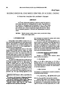
3.1. Influence of sliding velocity on the life of carbon coating Fig. 2 shows the influence of sliding velocity on the coating life (in cycles). As can be seen, SiC displays much longer life at low sliding velocity (almost two orders of magnitude) as compared with AI203. At the highest sliding velocity the difference in the life values has decreased to approximately one order of magnitude.
3.2. Influence of sliding velocity on the coeffu:ient of friction Fig. 3 shows the influence of sliding velocity on the initial friction coefficient/,to (measured right after an inertial spike observed at high velocities) ( Fig. 3 (a) ), and the steady-state friction coefficient/as (Fig. 3(b)) for both ceramics. Lines in those figures represent polynomial fitting. Fitting of the
104
A.G. Khurshudov et aL / Wear 205 (1997) I01-111
~o
~ - ~ ; ~ ......
\
42000 ~
[ ---O -A*,o,,
0.4S
~
0.4
;E
o.35
•~
0.3
.
~
{ o
~
, O@
]o~
~
350
~
I
10
i
i
•
•
t
. . . .
Fig. 4 presents the influence of sliding velocity on the ceramic pin wear rate. While the wear rate of SiC was almost independent of velocity, the wear rate of AI203 increased rapidly at ~ 11 m s - I.
. . . .
i
. . . .
20
I~
iO
Sliding v©IociPy, m/s
Slidingvelocity,m/s Fig. 2. Slidingvelocity effect on the life of the carbon-coatedthin-filmdisk.
3.3. Influence of sliding velocity on the ceramic pin wear
i
$
I00
SiC data in Fig. 3(b) does not include a data point at 0.5 m s - J, which has repeatedly shown much lower friction than the other points. For the velocity range 0.5-4-6 m s - i,/,to was found to increase slightly with increasing sliding velocity for both ceramics (Fig. 3 ( a ) ) . Above this velocity range, SiC displayed a constant Po while AI203 displayed a sharp increase i n / ~ at 11 m/s. The steady-state friction coefficient of A1203 was found to slightly increase with increasing sliding velocity. In contrast, SiC displayed a slight decrease in P-0 with increasing velocity.
•
0.25
0.2 O0.l
(a)
0
(bl ~."
.
0.$
@
o.4s '~ o
0.4
~
0.35
~
0
0
~'0
~... ------ """
0.3 0.25
0
o t
0.2
i
i
•
. . . .
i
i
3
.
,
.
.
!
.
,
,
,
IS
tO
2o
S l i d i n g v e l o c i t y , m/s
Fig. 3. Slidingvelocity effect on the initial (a) and steady-slate (b) coefficients of friction.
E
?
i" 5O
40
4. Discussion 4.1. Friction and wear mechanisms
~,o
_
-
-
-
-
. . . - . -. .
.
. . . . .
o
4. I. 1. Alumina The increase of the initial friction coefficient P.o in the sliding velocity range 0-4 m s - J (Fig. 3(a) ) may be a result of the visco-clastic response of the carbon coating-ceramic slider interface to high speed shearing (shear rate effect). Not only polymer, but even metals show significant strength increase at high strain rates. The increase of the steady-state coefficient of friction with increasing velocity can be explained by an increase in the real area of the contact. There was found a good linear correlation between the coefficient of friction obtained at different velocities (both initial and final, because of the short sliding distances for A1203) and the radius of the ceramic pin wear scar (Fig. 5). Abrasive wear of the alumina pin tip increased the contact area, made it more smooth and, therefore, increased the real contact area. The fact that, beginning from ~ 11 m s - i some changes occurred at the interface is better seen from the rapid increase
$
I$
I0
Sliding velocity, m/s F i g . 4 . S l i d i n g v e l o c i t y e f f e c t on the w e a r r a t e o f ceramic p i n .
0.45
g
-~-"0i
0.4
" it' ~ i
~
/
~
o.35 . g
0.2S
•
0.2
.... 35
' .... 4O
I, 45
, • .'-,
, ,I
5O
,, 55
, , 6O
P i n wear scar radius, p m
Fig. 5. Thecoefficientof friction vs. the radiusof AI~O3pin wearscar.
A.G. Khurslmdov et al. I Wear 20$ (1997) I01-111
of both the initial friction coefficiem ( Fig. 3(a) ) and the wear rate of alumina (Fig. 4). SEM analysis of the worn alumina pin surface showed, that a tongoc=like film was formed at the front side of th~ contact area beginning from ~ 4 . 0 m s -~ (Fig. 6(a) and 6 ( b ) ). This film consists of fine agglomerated wear particles, which are a result of abrasive wear. In the sliding velocity range 0--4.0 m s - t, no film but only local agglomeration of wear particles was observed (Fig. 7). The nature of this film will be discussed below.
105
It is possible that, beginning from - I1 m s - t , frictional heating at the alumina-carbon coating interface significantly decreased strength of the Al203 surface with a corresponding increase in wear rate from about 4 × 10- s to 75 x ! 0 - ~ m m 3 N - t m - t (Fig. 4). As a result of both surface fatigue and thermal cracking of the alumina, some grains or grain clusters delaminate from the A!203 surface. After the grain detachmerit, a non-uniform surface with sharp cutting edges was formed. Fig. 8 presents SEM pictures which show initiation
Fig. 6. Worn AI203pin surfacewiththe tongan-lihefilm (a) formedof fine wear particles (b) after sliding at 4.0 m s -t. Arrowsshow a direction of sliding.
Fig, 8, SequenceofSEM m i c s u g ~ showingthe in~r-grannL~~ l d n g and fracture processobservedon aluminaal low sliding velocity (0.5 m s - t). Arrowsshowa direction of sliding. (a) Initiationof gl'ainb o ~ Fig. 7. Wear particle agglomeration on the surface of an A1203 pin after sliding at 0,5 m s- i. Arrow shows a direction of sliding,
cracking. (b) Surface pot¢ (in,:ial or causud by grain detachment), The pore is partly filled with the mixture ofaluminaand amorphouscarbon wear particles. (c) Surface pores are completely filled with wear particles.
106
A.G. Khurshudov et aL / Wear 205 (1997) I01-1 II
EDS analysis of the surface pores filled with wear particles has also shown, besides AI and O, high amounts of C originating from the carbon coating. Thus, fine panicles of amorphous carbon are probably cut off from the coating by the sharp A!203 asperities or particles and later transferred to the AI203 surface, preferentially to surface pores. EDS analysis of the alumina surface worn by abrasion, i.e. between surface pores, only revealed A! and O. The same wear process for alumina was found for high sliding velocities, where the delaminated grains belonged not to the initial surface layer, but alumina's bulk material, exposed to friction after the surface layer was worn out. This means that this mechanism of grain detachment is an intrinsic property of alumina specimens.
0,6
O
0,5
o
o
O
o
o,4 o,:) 0 ~
0.2
0.1
--0
0 i-,t, ,i .... 30
40
i ....
i ....
50
60
n .... To
! ....
- Po i ....
80
i~o
9~
Pin weaerscar radius, pm Fig. 9. The coefficient o f friction vs. the radius o f SiC pin wear scar.
4.1.2. S i C
Fig. I 0. Worn surface o f SiC ( I ) with the agglomerated wear particles (11) ( 0.5 m s - t). A r r o w shows a direction o f sliding.
As was the case for alumina, the increase ofpoin the sliding velocity range 0-6 m s - n may be a result of visco-elastic response of the carbon coating-SiC interface to high speed shearing (shear rate effect). Unlike alumina, both the initial and steady-state friction coefficientsof SiC were almostinde. pendent of sliding velocity (the only exception was the 0-6 m s-~ region for ~ ) . Also, the friction coefficient (both initial and steady-state) was independent of wear of the SiC pin (Fig. 9). The possible reason is: the wear scars for SiC were almost always far from round in shape and their radius measurements were relatively imprecise. The wear rate of SiC was relatively low (2-20X 10 - s mm 3 N -m m -m) and almost independent of sliding velocity. At 0.5 m s- ~ the dominant mild
of grain detachment
(Fig. 8(a)),
surface pores (initial
o r as
the result of grain detachment) partly filled with wear particles (amorphous carbon and alumina) (Fig. 8(b) ), and surface pores completely filled with wear particles (Fig. 8(c) ). Large wear particles, if they enter the interface, may cause severe damage of the carbon coating with the following fast failure. ...t
tlo
....
t ....
! ....
| ....
abrasion
which
wear mechanism
resulted
in a smooth
i ....
i ....
i ~
....
l l l , , , , I
sl 90 80 70 60 50 40 30
o
1o o
"
~
.
.
i 1
• - .~--
, ....
i ....
3
4
surface
(Fig. 10-I) and also formation of a large amount of fine (submicron) wear particles (Fig. 10-1I). EDS analysisofthe wear scar and the agglomerated wear particles showed Si, C and O indicating tribe-oxidation of SiC to SiOx (Fig. 11 ). No oxygen was observed on the initial surface of SiC. At higher sliding velocities (4-16.6 m s - ~) the worn SiC pins revealed the formation of a thin film on the contact surface.
1oo
20
of SiC was worn
i .... 5
i ....
i ....
! ....
s
6
7
8
9
.... to
(key} Fig. I I. EDS spectra of the worn SiC pin surface (see Fig. 10) (0.5 m s - [).
A.G. Klmrshudovet aL / Wear205 (1997) IOl-lll
Fig. I z. rribofilmformationon the surfaceof SiC pin ( 14 m s- t): general view (a), tdbofilmsmgmre (b). and the finewear panicles (c). Arrows showa directionof sliding. The observed film consisted of fine wear particles (Fig. 12 (c) ) which were transformed at the sliding interface into the uniform film (Fig. 12(a) and 12(b) ). EDS analysis of the film revealed a large amount of oxygen, again indicating tribo-oxidation of SiC. The absence of oxygen in the unworn SiC surface and the increasing amount of oxygen with increasing sliding velocity implies an increasing tribooxidation of SiC with increasing velocity. 4.2. Wear particle behavior and a tribofilm formation
The present study has shown that, for sliding velocities less than ~ 4 m s - I particle agglomeration was observed (see
107
Figs. 7 and I0), while for sliding velocities higher than ~ 4 m s - ' both types of ceramics showed a high tendency m the formation of the film made of wear particles. However, the mechanisms of film formation were very different for the ceramics investigated. The following definition of the tribofilm will be used in this paper: it is a film formed by some tribological phenomena (tribomechanical, tribocbemical, or a combination of both) at the sliding contact interface, The triboiilm is able m carry most of the contact load without cohesive failure. This definition allows one to separate a tribofilm formation process from a simple particle agglomeration. In the case of AI203, the tongue-like film was always formed outside the contact area. Fig. 6(b) shows that the film consists of fine ~ 1 p.m wear particles and the grain boundaries are hardly seen on the film surface. In the case of SiC, the film usually covered the contact area and had an imperfect shape (Fig. 12(a)). This difference implies the difference in the film structure. Although the alumina used in this study contains some amount of SiO~, prescnt at the AI20 ~ grain boundaries, this amount is very small. As a result, the wear particles o f a l w mina were mostly made just of pure AlzO3 which means that, in order to form some kind of unifurm and strong film (not just a pile of agglomerated particles), they should be sintered together again. According to Ref. [ 21 ], a kind of hot-pressed sintering process may take place at the AI203/AI203 sliding interface at a high temperature oftbe order ofg00 ~ I000 °C. In our case, high flash temperature, for example, may exist at some small contact area under both high normal load and sliding velocity. Calculations, using Eqs. (1) and (2) and the contact model of Section 2.3 predict a flash temperature of about 1000 °C for p. ffi0.3 and P = 0.02 N in an Ai203 pin/ rigid disk contact of I tun in diameter at 15 m s - t and about 250 °C at 4 m s - t. The latter temperature value is not enough for the hot-pressed sintering of alumina but 1000 °C may be enough. However, this temperature may be theoretically expected only at the contact interface, and not outside (inlet and outlet part of the interface), where we cannot assume very high normal load. So, the bonding mechanism of the agglomerates outside the contact area alumina wear particles is not clear. Possibly, this isjost a liquid-mediated adhesion of particles, the strength of which is enough to keep particles together, but not enough to carry the contact load. This will explain why no film was observed at the contact surface of Al:O3. A relatively large amount of soft SiOx may be formed on the SiC surface by different ways. First, it may be formed by a tribochemical reaction of SiC and H20 , as shown for SiC sliding in water by Ref. [22]. But, in our case of dry sliding this way does not look reasonable. Another way to form SiOx on SiC is heating. In general, SiC is very stable to oxidation and needs about 1000 °C or more to be oxidized under steady-state conditions. However, additional mechanical activation of the SiC surface by, for example, friction, may significandy reduce this value.
A.G, Khurshudov et al. I Wear 205 (1997) 101-111
108 140o Disk: "rhimfilm cnlttc,-cotted rijid disk n2OO •Nomal lind: 0.02 N Mh:m-ccetact di0Ja~4~ I ttm 100o .Sliding velodly: 0.5 - 16.6 m/i
& E ,~
, .41" Alumina
~o
6On
Micro-contact
.rr
,,~,,~ ~
• 8,"
. n'• ~-~"2oo
• - ~t ~ Macro-contact ~ . , . . ,~,..~....~....,. ± . , . ~ . . . L = . n-_.. 2
4
6
8
10
12
14
16
18
Sliding velocity, ra/s Fig. 13. Calculated flash temperature dependencies on ~liding velocity.
Flash temperatures of the order of 500 °C may, possibly, cause the following reaction [23]: SiC -I-202 ~ SiO 2 + CO2
(3 )
In order to analyze interfacial flash temperatures one requires the parameters mentioned in Section 2.3. Among others, the micro-contact radius a and normal load P acting at this micro-contact are the most difficult parameters to obtain. We cannot reasonably assume these values on the basis of the surface micro-geometry of the contacting pin and disk specimens. But the following may be reasonable assumptions. 1. Mean size of the micro-contacts between two surfaces is of the same order as mean size of the wear particles formed at the interface. 2. Sometimes, for a short time, the whole normal load P may be carried by one micro-contact only. Fig. 6(b) (forAl203)and Fig. 12(c) (for SiC)show that the mean characteristic size of wear particles is close to I p~m. Fig. 13 shows an effect of the sliding velocity on the calculated flash temperature at macro-contact (when the wear scar radius of 33-93 ~ m was used) and micro-contact (contact spot 1 p.m in diameter). It is obvious, that the macro-contact flash temperature should not be taken into consideration at all: the increment in temperature is always less than 5 °C. On the contrary, maximum flash temperature at the micro-contact reaches 1348 °C for alumina and 607 °C for SiC, using V = 16.6 m s - i. The local temperatures of that order were previously observed experimentally at the high-speed slidermagnetic rigid disk iDterface [24,25]. These temperatures, if present, may have a strong effect on the mechanical properties of wear particles, ceramic sliders and carbon coating. Some of the wear particles observed at the interface had a round shape ( Fig. 6 ( b ) ) while others had an elongated rol letlike shape (Fig. 12(c) ). This allows us to conclude that wear particles (at least, some part of them) were pulled by friction into the contact interface and deformed there into rollers. Fig. 14 shows the evolution of wear particle shape. At a low sliding velocity of O.5 m s - n (Fig. 14 (a)), wear particles were observed close to the periphery of a w c ~ Lack ~"d had a random shape. With a sliding velocity increase, particles were mostly observed on the wear track and gradually
Fig. 14. SiC and carbon.coated disk w e a r particles produced during sliding
at 0.5 (a), 8 (b) and 15 m s - ' (c). Onn:spondingestima~ contact temperatureswen: 3 °C, 320 °C and 570 °C. Arrowsshow a direction of sliding. changed their shape to elongated roller like (Fig. 14(b) and 14(c)). The main difference in the interfacial conditions of Fig. 14(a)-14(c) is the contact temperature. These figures show that the normal load itself is not enough to produce roller-like particles, but a high temperature is necessary. Fig. 15 summarizes the data of Fig. 6 and Figs. 10-14 and suggests five main possible types of behavior of wear particles (formed by abrasive mechanism) after entering the interface. If a wear particle enters the interface, then, under the effect of high pressure and high local heating (data of Fig. 13 may
A.~. glmrshudow et at I Wear 205 (1097) IOl-I I I Rn/t3~k contact imerface
surface
f
4 i [qovi~d~k
~om~ateo
surface
Fig. 15. Principles of wear panicle behavior at the contact interface: if particles enter the contact it may form a miler shape ( I ). it may be smeared (It) or crashed (tit). it may adhere to the ~ sick of the pin (IV), and it may leave the contact interface to join, after one cycle, panicles at the front side (V). Some pa~leles will be forced out of the contact (VI).
N~m~na pm
109
SiO~ and SiC are present in the observed on the SiC pin surface film. SiOx is much softer and may form a film itself. SiC particles are hard and cannot form a film on the sliding surface, but only if they are embedded in a soft matrix of SiO.. The presented data and discussion may be helpful in prediction of wear particle behavior in the case of, for example, contact magnetic recording, although the presence of a thin ( !- 4 nm ) lubricant layer may, most likely, affect the particle agglomeration process outside the contact area. Those particles that will be pulled into the sliding interface may be subjected to high load at high sliding speed. Materials which contain a relatively soft phase (like SiOx) or show tribooxidation tendencies may form a trihofilm on the surface. Other materials (A!203, for example) will form weax particles which agglomerate around the interface, sometimes entering it, leaving it, and entering it again. 4.3. Carbon coating life
Let us define the normalized coating life as following: (4)
Nnonn = N / d
~
carbon coating
Tr:bof~m
T ~ ~ SO,r ~ w~h
Fig. 16. The film structure for AI203 (a) and SiC (b) sliders,
be equally used for both micro-asperities and wear particles ), it can he deformed into roller shape (type I), smeared out over the pin or disk surface (type II), or crashed into fine fragments (type HI). The particle may also leave the contact without changing its shape, adhere to the rear side of the pin (type IV), or, after one cycle, join other particles at the entrance (type V). Particles of type II are probably responsible for the formed tribofilm on the SiC surface. Type VI corresponds to a wear particle which is forced out of the interface. If a large wear particle, observed for alumina (see Fig. 8(a) ) enters the interface, it may cause severe damage of the carbon coating with the following fast failure. Fig. 16 presents schematically the sliding interfaces for Ah0 3 (a) and a SiC pin (b) sliding against the carbon-coated disk. In the case of alumina, type-II wear particles were absent, resulting in particles agglomeration around the interface, but not at the interface (Fig. 16(a) ). In the case of SiC, soft, mostly SiOx-based wear particles were, most likely, smeared out over the pin surface forming a tribofilm. This, along with the data of EDS analysis (Fig. 1! ) imply that both
where N is the number of cycles before the coating failure, d is the mean diameter of the contact area calculated as an average of the initial (Henzian) and final (at tbe time of failure) contact diameters. Its dimension is cycles per micrometer. Fig. 17 presents the normalized life of the carbon coating in sliding contact against the ceramic sliders versus the calculated flash temperature. The resultant size of the contact area of the ceramic pin is dependent on both the wear resistance of the ceramic itself and on the coating life (time of sliding). This means that, in different tests, sliding distances for the disk surface were differenteven if the numberofcycles was the same, because of difference in tbe final size of pin wear scar. The higher is wear of the pin the larger is sliding distance for the disk surface. To exclude this "geometrical" effect on the obtained data, coating life was divided by mean contact diameter. Normalized coating life in Fig. 17 reflects 10 .Q
~":~
........
t00 i
1~0 i
~""'"'o ........
"
zooo
o
"-";
0.t 10
) 100
0.1 lifo
Flash temperature. "C Fig. I 7. Normalized carbon coating life vs. the calculated flash temporana~. Dashed lines represent fitting by a power low.
110
A.G, Kharshudov et al. / Wear 205 (1997) I01-1 I1
Fig. 18. Micro-cutting of the carbon-coated dixk ~y ~.q AhO3 pin at I5 m s- '. Allow shows a dilcctioo of sliding,
material wear properties, but is mostly free of "geometrical" effect. A straight line is fitted through five points (three furthest right points for SiC and two for alumina). Fig. 17 indicates that there is a common mechanism which controls coating life for both pin materials in the high-temperature region. Using Figs. 2 and 17, two different regions may be distinguished. 1. A low-speed (flash temperature is less than, probably, 100 °C) region, where the difference in coating life values for SiC and A1203 sliders was very high. The normalized coating life (dashed lines) is almost independent of the flash temperature. 2. A high-speed (flash temperature is more than about 400 °C) region, where: (1) the difference in lives between SiC and AI203 became relatively small compared with that at the velocity less than I m s - j , and (2) the norrealized life data for both ceramics fit the same dependence on the flash temperature. On the basis of Fig. 8 we may conclude that the main phenomenon which determined the carbon coating life against alumina slider was the observed inter-granular cracking of alumina followed by the grain detachment. Microcutting of thin (35 nm) carbon coatings by generated large wear particles (delaminated grains or grain clusters) and sharp edges caused rapid destruction of the carbon coating after only a few hundred cycles (Fig. 2). Fig. 18 shows the disk surface after sliding at 15 m s - i against an A1203 pin. Abrasive scratches can be clearly seen. This means that the same coating destruction mechanism as at low velocity is still valid for high-velocity sliding. However, coating failure occurs faster because of higher flash temperatures. The main reason why SiC provided longer life at low sliding velocities (see Fig. 2) compared to that of alumina may be that SiC formed a relatively uniform (not necessarily smooth) worn surface without detachment of large grains (see Fig. I 0-I). This caused a mild wear of the carbon coating only and provided its long life. With a sliding velocity and contact temperature increase, life of the carbon coating sliding against SiC decreased rap-
idly and became relatively close to that of alumina beginning from ~400 °C (but was still higher). Frictional heating is, most likely, responsible for that. High interfacial temperature is able to cause chemical wear of the carbon coating ( carbon oxidization with the following CO or/and CO2 chemisorption [26] ). Contact temperature was roughly proportional to the sliding velocity (Fig. 13), and one may expect a gradual decrease in the carbon coating life with the sliding velocity increase (as in the case of SiC (Fig. 2)). At the highest sliding velocities (about 14-16.6 m s - i ) , when failure occurred after only a few seconds, high interfacial temperature itself may cause a decrease in hardness and strength of the carbon coating and metallic substrate, which will result in instant failure. Fig. 17 shows, that if the flash temperature exceeds ~ 1300 °C, then coating failure will be almost instant. It also shows the maximum possible number of normalized life cycles for the given flash temperature (this is relevant for the region close to the boundary line). For example, if the flash temperature is equal m 200 °C, one can expect a normalized life value of about 5-7 for alumina and 60-80 for SiC, but the "theoretical" limit for some hypothetical material will be about 100-110.
5. Conclusion For the purpose of tribological improvement of the magnetic head slider-rigid disk interface through the understanding the friction and wear mechanism, two different ceramic materials such as SiC and AI203 were tested using pin-ondisk test equipment against a carbon-coated rigid disk. The obtained results may be summarized as follows. 1. The main wear mechanism for both ceramics was abrasion. A silicon carbide slider provided much longer life of an unlubricated carbon-coated thin-film disk than a slider made of alumina. Grain detachment from the alumina slider surface followed by severe abrasion of the carbon coating by the large wear particles and/or the formed sharp edges was found to be the main reason of the short coating life. 2. Failure of the carbon coating, sliding at low velocity against a ceramic slider, occurred mainly because of abrasive wear. At high velocity ( >400 °C), a high frictiongenerated flash temperature was mostly responsible for coating failure. 3. A model (see Fig. 15) which describes behavior of wear particles at the contact interface was suggested on the basis of SEM observations. If particles enter the interface then five basic types of p',a'ticle behavior can be described as follows: it can take a roller shape (I), it can be smeared out (H), crashed (lll), it can adhere to the rear side of the pin (IV), and it can leave the interface and return (after one rotation) to the front side of the pin (V).
A.O. Klmrslu,dov et aL I Wear 205 (1997) I01-111
4. A film formation of agglomerated wear particles was
observed for both ceramic pins above a sliding velocity of ~ 4 m s - t. SiC formed a relatively strong tribofilm (able to carry a load) on its sliding surfaces. This tribofilm is expected to consist of a SiOx matrix with embedded SiC particles. In the case of AI203, a film was made just of a g g l o m e r a t e d A1203 particles, w a s not able to carry a l o a d , and, as a result, w a s observed only outside the eoutact area,
Acknowledgements Authors w o u l d like to thank Mr. Y. Miyake and Mr. S. Nagaike from the H e a d Disk Interface Design Dept., A d v a n c e d Products a n d T e c h n o l o g y Development Division, Data Storage a n d Retrieval Systems Div., HITACHI, Ltd. for their support o f this work. The authors would like to thank Dr. K. Adachi for useful discussions.
References [I] H. Hamilton, R. Anderson and K. Goods~, Contact peq~endicuinr recording on rigid media, Trans. Magn., 27 (6) (1991) 4921-4926. [2] H. Tsai and D.B. Bogy, Charactmizationof dlamond-likecm'oonfilms and their application as overcoats on thin-film media for magnetic recording. J. Vac. Sci. TechnoL A. 5 (1987) 3287-3312. [31 B. Bhushan. Masnetic slider/rigid disk su~trate materials and disk texturing techniques - - s~tus and future outlook, Ad~. Inf. Storage Syst.. 5 (1993) 175-209. [4] S. Cha,~rasekarand B. Bhushaa, FH¢~onand ~ of ~,ramics for magnetic recording applications- Part 1: a review, Trans. ASMF~ J. Tribol.. 112 (1990) 1-16. [51 B, Bhushan. Magnetic head-media interface: Temperaturcs-- P ~ 3: Application to rigid disks. Trans. ASME. J. Tribol.. 114 (1992) 420-430. [6] M.-Y. Chn, B. Bhushan and L.C. DeJo~ghe.Wear behnviof of ceramic sliders in sliding contact with rigid magnetic thin-film disks, Tribol. Trans., 32 (1992) 603-610. [7 ] A. Tcrada. Y. Ohtani, Y. Kimachi and F. Yoshimura.Wear properties of lubricated medium surface under high velocity head sliding, TriboL Mech. Magn. Storage Syst.. STLE SP-25. (1988) 69-73. [ 8 ] Y. Kawakubo, Failure mechanism of coated magnetic recording disk during pin-on-disk sliding test, Proc. Jpn. lnt. Tribol. Conf.. Nagoyo. 1990, pp. 1313--1314.
III
[9] Y. Kok~u, H. Maemmolo, H. Inahn, S. Fu~mal~, M. Kiloh aed K. Abe, l~opertiesof dlamond-like cad~om fdm and its~ ~m a protectivelayer in lhin-filmmapetic eecording disks,/FEE Trans. Maglt. 29 (1993) 3942-3944. [ I0] R. Koishi,T. Yamamolo amd M. Shinoha~ Chemical structureand durability of a IMasma-polynm'~M p~u~Jve layer for thin-Nm n ~ d~s, TriboI. Trons..36 (1993) 49--S4. [11] S. O h ~ F. Yoggmm~ Y. KJmadg and A. Ter~ln. We~ pz~penks of spuge~l y - F e ~ thin film ~ k s . ~nEE, SP-22 (1987) 110-115. [ 12] Y. Kawakubo a~l Y. YaMsa,T ~ pin weagtest on thiwlnm disk,ASM E Trons.,J. Tribol.,117 (1995) 297-301. [13l R. Koka and A.R. Kumm-an, Visual/zmion and analysisof particulate bmldup on the lea~mg edge tapem of slide~,.4dv. Inf.. Storage SyO.,
2 (1991) 161~171. [ 14] B. Hilk~-and G.P. Singh, Interactionof com~ninam pednickswith the pmriculate sliderl disk interfoce.Adv, l~. Stomge Syst,. 2 (1991) 173180. [15] S.K. Ganapmhi, R.D. Balamen and F.E. Talke, SEM study o f w e l mechmisms in ~ thin film disim with different overr,~Is, Trans. ASME, J. Tribol., !14 (1992) 263-269. [ 16] B.D. Sworn.D.B. Bogy, C.S. Bhatia md B. Bheshan, Tribochemlc~ effocts of vadons gases and water vapor om thin film magnetic disks with ~ overcoats, Trans. ASME, J.Tribol., 113 (1991) 689-693. [ 17] Y. Kawakuhn,Tdbology of rigid ~ recofd/ng disks, J. Magic Soc. Jptc, 11 (!) (1987) 4-8. [18l Y. Kawakubo. H. ~ Z. Tsutsumi and J. Shimizu, Spherical pln sliding test on coated m a ~ n~mrdig disks. Tribol. Meclt Magn. S:orageSysL,ASLE SP-21 (1986) I 18-124. [19] A. Khulshndov, M. Olsson and K. Kato,Micro~rihnlngicalpheaomeaa in slidingcontactof ceramic materialsand DLC, Proc. InL Tribology Conf., Yokolmma, Japan, 1995, Vol. 3, pp. 1937-1942. [20] J.F. Agcha~ 'Fae t e ~ of ml~ing surfaces. Wear, 2 (19581 1959) 438-455. [21 ] K. Adachi, K. Kato and R. Takizawa. Snmothing effect of the light body compaction on alumias surface in slid~g contact,Pro¢. 22rid Leeds-Leon Syrup.on TnboloKy, France, 1995, in pleu. [22] H. Tomizawa and T.E. F'mcher.Friction amdwere-of siliona nitlgle and silicon carbidein water, hyd~rodymniclobt'icafioaat low slidiag speed ob~Jnedbytribochemicalwe~.ASL~Trons.,30(1) (1986) 41--46. [23] G. Heinicke,Tr/bochembtry, Akademie-Vedng, Berlin,1984. [24] S. Suzuki and F.E. Kennedy, The detectionof flashtempermmes in sliding cannot by the methodof uibo-induced thermoluminescence. Trans. ASMF~J. TrO~ol. 113 ( 1991) 120-127. [2,5] S. Bait-, !. Greea and B. Bheslum, Meastwemeat of asperity t e ~ of a readlwnle head slider bearing in hard magnetic w~otlfing eYtsks.Trans. ASME, J. Tribol.. 113 (1991) 547-5.54. [26] B, Macchon, N. Heirmmand M,R. Khan, Evidence of ffibocheraical wear on amorphous cat'bontMn films. IEEE Trans. Magi. 26 (1990) 168-170.