IEEE/ACM TRANSACTIONS ON NETWORKING, VOL. 19, NO. 3, JUNE 2011
617
Maelstrom: Transparent Error Correction for Communication Between Data Centers Mahesh Balakrishnan, Tudor Marian, Kenneth P. Birman, Fellow, ACM, Hakim Weatherspoon, and Lakshmi Ganesh
Abstract—The global network of data centers is emerging as an important distributed systems paradigm—commodity clusters running high-performance applications, connected by high-speed “lambda” networks across hundreds of milliseconds of network latency. Packet loss on long-haul networks can cripple applications and protocols: A loss rate as low as 0.1% is sufficient to reduce TCP/IP throughput by an order of magnitude on a 1-Gb/s link with 50-ms one-way latency. Maelstrom is an edge appliance that masks packet loss transparently and quickly from intercluster protocols, aggregating traffic for high-speed encoding and using a new forward error correction scheme to handle bursty loss. Index Terms—Data centers, forward error correction (FEC), TCP/IP.
I. INTRODUCTION HE EMERGENCE of commodity clusters and data centers has enabled a new class of globally distributed highperformance applications that coordinate over vast geographical distances. For example, a financial firm’s New York City data center may receive real-time updates from a stock exchange in Switzerland, conduct financial transactions with banks in Asia, cache data in London for locality, and mirror it to Kansas for disaster-tolerance. To interconnect these bandwidth-hungry data centers across the globe, organizations are increasingly deploying private “lambda” networks. Raw bandwidth is ubiquitous and cheaply available in the form of existing “dark fiber.” However, running and maintaining high-quality loss-free networks over this fiber is difficult and expensive. Though high-capacity optical links are almost never congested, they drop packets for numerous reasons—dirty/degraded fiber [1], misconfigured/malfunctioning hardware [2], [3], and switching contention [4], for example—and in different patterns, ranging from singleton drops to extended bursts [5], [6]. Noncongestion loss has been observed on long-haul networks as well maintained as Abilene/Internet2 and National LambdaRail [2], [3], [6], [7]. The inadequacy of commodity TCP/IP in high bandwidthdelay product networks is extensively documented [8]–[10].
T
Manuscript received June 24, 2009; revised March 23, 2010; accepted June 13, 2010; approved by IEEE/ACM TRANSACTIONS ON NETWORKING Editor T. Wolf. Date of publication May 12, 2011; date of current version June 15, 2011. A conference version of this paper appeared in the Proceedings of the 5th USENIX Symposium on Networked Systems Design and Implementation (NSDI), San Francisco, CA, April 16–18, 2008. M. Balakrishnan is with Microsoft Research Silicon Valley, Mountain View, CA 94041 USA (e-mail:
[email protected]). T. Marian, K. P. Birman, H. Weatherspoon, and L. Ganesh are with Cornell University, Ithaca, NY 14853 USA (e-mail:
[email protected]; ken@cs. cornell.edu;
[email protected];
[email protected]). Digital Object Identifier 10.1109/TNET.2011.2144616
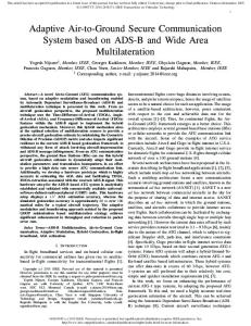
TCP/IP has three major problems when used over such networks. First, TCP/IP suffers throughput collapse if the network is even slightly prone to packet loss. Conservative flow control mechanisms designed to deal with the systematic congestion of the commodity Internet react too sharply to ephemeral loss on overprovisioned links—a single packet in 10 000 is enough to reduce TCP/IP throughput to a third over a 50-ms gigabit link, and one in a thousand drops it by an order of magnitude. Second, real-time or interactive applications are impacted by the reliance of reliability mechanisms on acknowledgments and retransmissions, limiting the latency of packet recovery to at least the round-trip time (RTT) of the link. If delivery is sequenced, as in TCP/IP, each lost packet acts as a virtual “roadblock” in the first-in–first-out (FIFO) channel until it is recovered. Third, TCP/IP requires massive buffers at the communicating end-hosts to fully exploit the bandwidth of a long-distance high-speed link, even in the absence of packet loss. Deploying new loss-resistant alternatives to TCP/IP is not feasible in corporate data centers, where standardization is the key to low and predictable maintenance costs; neither is eliminating loss events on a network that could span thousands of miles. Accordingly, there is a need to mask loss on the link from the commodity protocols running at end-hosts, and to do so rapidly and transparently: rapidly, because recovery delays for lost packets translate into dramatic reductions in application-level throughput; transparently, because applications and OS networking stacks in commodity data centers cannot be rewritten from scratch. Forward error correction (FEC) is a promising solution for reliability over long-haul links [11]. Packet recovery latency is independent of the RTT of the link. While FEC codes have been used for decades within link-level hardware solutions, faster commodity processors have enabled packet-level FEC at endhosts [12]. End-to-end FEC is very attractive for communication between data centers: It is inexpensive, easy to deploy and customize, and does not require specialized equipment in the network linking the data centers. However, end-host FEC has two major issues. First, it is not transparent, requiring modification of the end-host application/OS. Second, it is not necessarily rapid. FEC works best over high, stable traffic rates and performs poorly if the data rate in the channel is low and sporadic [13], as in a single end-to-end channel. In this paper, we present the Maelstrom Error Correction appliance, a rack of proxies residing between a data center and its WAN link (see Fig. 1). Maelstrom encodes FEC packets over traffic flowing through it and routes them to a corresponding appliance at the destination data center, which decodes them and recovers lost data. Maelstrom is completely transparent. It does
1063-6692/$26.00 © 2011 IEEE
618
IEEE/ACM TRANSACTIONS ON NETWORKING, VOL. 19, NO. 3, JUNE 2011
Fig. 1. Maelstrom communication path.
not require modification of end-host software and is agnostic to the network connecting the data centers. Also, it eliminates the dependence of FEC recovery latency on the data rate in any single node-to-node channel by encoding over the aggregated traffic leaving the data center. Additionally, Maelstrom uses a new encoding scheme called layered interleaving, designed especially for time-sensitive packet recovery in the presence of bursty loss. Maelstrom’s positioning as a network appliance reflects the physical infrastructure of modern data centers. Clean insertion points for proxy devices exist on the high-speed lambda links that interconnect individual data centers to each other. Maelstrom can operate as either a passive or active device on these links. Of the three problems of TCP/IP mentioned, Maelstrom solves the first two—throughput collapse and real-time recovery delays—while operating as a passive device that does not intervene in the critical communication path. In active mode, Maelstrom handles the additional problem of massive buffering requirements as well, at the cost of adding a point of failure in the network path. Maelstrom belongs to a class of solutions known as performance-enhancing proxies (PEPs) [14]. PEPs have been used to transparently mitigate inefficiency at different layers in settings such as satellite links and wireless networks. A number of commercial PEP products [15], [16] perform TCP and application-level acceleration over long-distance links. To the best of our knowledge, our work is the first research project to examine the use of FEC-based PEPs for communication between data centers. The contributions of this paper are as follows. • We explore end-to-end FEC for long-distance communication between data centers and argue that the rate sensitivity of FEC codes and the opacity of their implementations present major obstacles to their usage. • We propose Maelstrom, a gateway appliance that transparently aggregates traffic and encodes over the resulting high-rate stream. • We describe layered interleaving, a new FEC scheme used by Maelstrom where, for constant encoding overhead, the latency of packet recovery degrades gracefully as losses get burstier. • We discuss implementation considerations. We built two versions of Maelstrom. One runs in user mode, while the other runs within the Linux kernel. • We evaluate Maelstrom on Emulab [17] and show that it provides near-lossless TCP/IP throughput and latency over
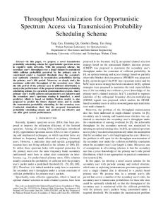
Fig. 2. Loss rates on TeraGrid.
lossy links and recovers packets with latency independent of the RTT of the link and the rate in any single channel. II. MODEL Loss Model: Packet loss typically occurs at two points in an end-to-end communication path between two data centers, as shown in Fig. 1—in the wide-area network connecting them and at the receiving end-hosts. Loss in the lambda link can occur for many reasons, as stated previously: transient congestion, dirty or degraded fiber, malfunctioning or misconfigured equipment, low receiver power, and burst switching contention are some reasons [18], [1]–[4]. Loss can also occur at receiving end-hosts within the destination data center. These are usually cheap commodity machines prone to temporary overloads that cause packets to be dropped by the kernel in bursts [13]. This loss mode occurs with UDP-based traffic, but not with TCP/IP, which advertises receiver windows to prevent end-host buffer overflows. What are typical loss rates on long-distance optical networks? The answer to this question is surprisingly hard to determine, perhaps because such links are a relatively recent addition to the networking landscape and their ownership is still mostly restricted to commercial organizations disinclined to reveal such information. One source of information is TeraGrid [19], an optical network interconnecting major supercomputing sites in the U.S. TeraGrid has a monitoring framework within which 10 sites periodically send each other 1-Gb/s streams of UDP packets and measure the resulting loss rate [20]. Each site measures the loss rate to every other site once an hour, resulting in a total of 90 loss-rate measurements collected across the network every hour. Fig. 2 shows that between November 1, 2007 and January 25, 2008, 24% of all such measurements were over 0.01%, and a surprising 14% of them were over 0.1%. After eliminating a single site (Indiana University) that dropped incoming packets steadily at a rate of 0.44%, 14% of the remainder were over 0.01%, and 3% were over 0.1%. These numbers may look small in absolute terms, but they are sufficient to bring TCP/IP throughput crashing down on high-speed long-distance links. Conventional wisdom states that optical links do not drop packets. Most carrier-grade optical equipment is configured to shut down beyond bit error rates of 10 —one out of a trillion bits. However, the reliability of
BALAKRISHNAN et al.: MAELSTROM: TRANSPARENT ERROR CORRECTION FOR COMMUNICATION BETWEEN DATA CENTERS
the lambda network is clearly not equal to the sum of its optical parts. In fact, it is less reliable by orders of magnitude. As a result, applications and protocols such as TCP/IP, which expect extreme reliability from the high-speed network, are instead subjected to unexpectedly high loss rates. Of course, these numbers reflect the loss rate specifically experienced by UDP traffic on an end-to-end path and may not generalize to TCP packets. Also, we do not know if packets were dropped within the optical network or at intermediate devices within either data center, though it is unlikely that they were dropped at the end-hosts. Many of the measurements lost just one or two packets, whereas kernel/NIC losses are known to be bursty [13]. Furthermore, loss occurred on paths where levels of optical link utilization (determined by 20-s moving averages) were consistently lower than 20%, ruling out congestion as a possible cause, a conclusion supported by dialog with the network administrators [21]. What are some possible causes for such high loss rates on TeraGrid? A likely hypothesis is device clutter: The critical communication path between nodes in different data centers is littered with multiple electronic devices, each of which represents a potential point of failure. Another possibility is that such loss rates may be typical for any large-scale network where the cost of immediately detecting and fixing failures is prohibitively high. For example, we found through dialog with the administrators that the steady loss rate experienced by the Indiana University site was due to a faulty line card, and the measurements showed that the error persisting over at least a three-month period. Other data points for loss rates on high-speed long-haul networks are provided by the backbone networks of Tier-1 ISPs. Global Crossing reports average loss rates between 0.01% and 0.03% on four of its six interregional long-haul links for the month of December 2007 [22]. Qwest reports loss rates of 0.01% and 0.02% in either direction on its trans-Pacific link for the same month [23]. We expect privately managed lambdas to exhibit higher loss rates due to the inherent tradeoff between fiber/equipment quality and cost [24], as well as the difficulty of performing routine maintenance on long-distance links. Consequently, we model end-to-end paths as dropping packets at rates of 0.01% to 1% to capture a wide range of deployed networks. III. EXISTING RELIABILITY OPTIONS TCP/IP is the default reliable communication option for contemporary networked applications, with deep, exclusive embeddings in commodity operating systems and networking APIs. Consequently, most applications requiring reliable communication over any form of network use TCP/IP. As noted earlier, TCP/IP has three major problems when used over high-speed long-distance networks. 1) Throughput collapse in lossy networks: TCP/IP is unable to distinguish between ephemeral loss modes—due to transient congestion, switching errors, or bad fiber—and persistent congestion. The loss of one packet out of 10 000 is sufficient to reduce TCP/IP throughput to a third of its lossless maximum. If one packet is lost out of a thousand, throughput collapses to a thirtieth of the maximum.
619
The root cause of throughput collapse is TCP/IP’s fundamental reliance on loss as a signal of congestion. While recent approaches have sought to replace loss with delay as a congestion signal [25], or to specifically identify loss caused by noncongestion causes [26], older variants—prominently Reno—remain ubiquitously deployed. Other work such as ETEN [27] introduces explicit feedback to the sender regarding corruption-based loss, typically requiring intermediate routers to be modified. 2) Recovery delays for real-time applications: Conventional TCP/IP uses positive acknowledgments and retransmissions to ensure reliability. The sender buffers packets until their receipt is acknowledged by the receiver and resends if an acknowledgment is not received within some time period. Hence, a lost packet is received in the form of a retransmission that arrives no earlier than 1.5 RTTs after the original send event. The sender has to buffer each packet until it is acknowledged, which takes one RTT in lossless operation, and it has to perform additional work to retransmit the packet if it does not receive the acknowledgment. Also, any packets that arrive with higher sequence numbers than that of a lost packet must be queued while the receiver waits for the lost packet to arrive. 3) Massive buffering needs for high throughput applications: TCP/IP uses fixed-size buffers at receivers to prevent overflows. The sender never pushes more unacknowledged data into the network than the receiver is capable of holding. In other words, the size of the fluctuating window at the sender is bounded by the size of the buffer at the receiver. In high-speed long-distance networks, the quantity of in-flight unacknowledged data has to be extremely high for the flow to saturate the network. Since the size of the receiver window limits the sending envelope, it plays a major role in determining TCP/IP’s throughput. The default receiver buffer sizes in many standard TCP/IP implementations are in the range of tens of kilobytes, and consequently inadequate receiver buffering is the first hurdle faced by most practical deployments. A natural solution is to increase the size of the receiver buffers. However, in many cases, the receiving end-host may not have the spare memory capacity to buffer the entire bandwidth-delay product of the long-distance network. The need for larger buffers is orthogonal to the flow control mechanisms used within TCP/IP and impacts all variants equally. A. Case for (and Against) FEC FEC encoders are typically parameterized with an tuple. For each outgoing sequence of data packets, a total of data and error correction packets are sent over the channel, resulting in an encoding overhead of . Significantly, redundancy information cannot be generated and sent until all data packets are available for sending. Consequently, the latency of packet recovery is determined by the rate at which the sender transmits data. Generating error correction packets from less than data packets at the sender is not a viable option—even though the data rate in this channel is low, the receiver and/or network could be operating at near full capacity with data from other senders. FEC is also very susceptible to bursty losses [28]. Interleaving [29] is a standard encoding technique used to combat
620
IEEE/ACM TRANSACTIONS ON NETWORKING, VOL. 19, NO. 3, JUNE 2011
Fig. 3. Interleaving with index 2: separate encoding for odd and even packets.
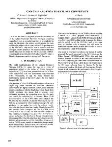
bursty loss, where error correction packets are generated from alternate disjoint substreams of data rather than from consecutive packets (see Fig. 3). For example, with an interleave index of 3, the encoder would create correction packets separately from three disjoint substreams: the first containing data packets numbered , the second with data packets numbered , and the third with data . Interleaving packets numbered adds burst tolerance to FEC, but exacerbates its sensitivity to sending rate. With an interleave index of and an encoding rate of , the sender would have to wait for packets before sending any redundancy information. These two obstacles to using FEC in time-sensitive settings—rate sensitivity and burst susceptibility—are interlinked through the tuning knobs. An interleave of and a rate of provides tolerance to a burst of up to consecutive packets. Consequently, the burst tolerance of an FEC code can be changed by modulating either the or the parameters. Increasing enhances burst tolerance at the cost of network and encoding overhead, potentially worsening the packet loss experienced and reducing throughput. In contrast, increasing trades off recovery latency for better burst tolerance without adding overhead. As mentioned, for higher values of , the encoder has to wait for more data packets to be transmitted before it can send error correction packets. We assume that the parameter is fixed to a small constant value; increasing it adversely impacts recovery latency, yet it needs to be large enough that different combinations can provide reasonable levels of overhead (for example, with , setting produces an expensive code with 100% encoding overhead). Importantly, once the FEC encoding is parameterized with a rate and an interleave to tolerate a certain burst length (for example, , and to tolerate a burst of length ), all losses occurring in bursts of size less than or equal to are recovered with the same latency, and this latency depends on the parameter. Ideally, we would like to parameterize the encoding to tolerate a maximum burst length and then have recovery latency depend on the actual burstiness of the loss. At the same time, we would like the encoding to have a constant rate for network provisioning and stability. Accordingly, an FEC scheme is required where latency of recovery degrades gracefully as losses get burstier, even as the encoding overhead stays constant. IV. MAELSTROM DESIGN AND IMPLEMENTATION A. Basic Mechanism The basic operation of Maelstrom is shown in Fig. 4. At the send-side data center, it intercepts outgoing data packets and
Fig. 4. Basic Maelstrom mechanism: Repair packets are injected into stream transparently.
routes them to the destination data center, generating and injecting FEC repair packets into the stream in their wake. A repair packet consists of a “recipe” list of data packet identifiers and FEC information generated from these packets. In the example in Fig. 4, this information is a simple XOR. The size of the XOR is equal to the MTU of the data center network, and to avoid fragmentation of repair packets, we require that the MTU of the long-haul network be set to a slightly larger value. This requirement is easily satisfied in practice since gigabit links very often use “Jumbo” frames of up to 9000 B [30], while LAN networks have standard MTUs of 1500 B. At the receiving data center, the appliance examines incoming repair packets and uses them to recover missing data packets. On recovery, the data packet is injected transparently into the stream to the receiving end-host. Recovered data packets will typically arrive out of order at the end-host, and hence it is vital that packets be recovered by the appliance extremely quickly to avoid triggering mechanisms in commodity stacks that interpret out-of-order arrival as congestion in the network. B. Flow Control While relaying TCP/IP data, Maelstrom has two flow control modes: end-to-end and split. Fig. 5 illustrates these two modes. End-to-End Mode: With end-to-end flow control, the appliance treats TCP/IP packets as conventional IP packets and routes them through without modification, allowing flow-control to proceed between the end-hosts. Importantly, TCP/IP’s semantics are not modified. When the sending end-host receives an acknowledgment, it can assume that the receiving end-host successfully received the message. In end-to-end mode, Maelstrom functions as a passive device, snooping outgoing and incoming traffic at the data center’s edge. Its failure does not disrupt the flow of packets between the two data centers.
BALAKRISHNAN et al.: MAELSTROM: TRANSPARENT ERROR CORRECTION FOR COMMUNICATION BETWEEN DATA CENTERS
Fig. 5. Flow control options in Maelstrom. (a) End-to-end flow control. (b) Split flow control.
Split Mode: In split mode, the send-side appliance acts as a TCP/IP endpoint, terminating connections and sending back ACKs immediately before relaying data on appliance-to-appliance flows. Split mode is extremely useful when end-hosts have limited buffering capacity since it allows the receive-side appliance to buffer incoming data over the high-speed long-distance link. It also mitigates TCP/IP’s slow-start effects for short-lived flows. In split mode, Maelstrom has to operate as an active device inserted into the critical communication path. Its failure disconnects the communication path between the two data centers. Is Maelstrom TCP-Friendly?: While Maelstrom respects end-to-end flow control connections (or splits them and implements its own proxy-to-proxy flow control as described above), it is not designed for routinely congested networks. The addition of FEC under TCP/IP flow control allows it to steal bandwidth from other competing flows running without FEC in the link, though maintaining fairness versus similarly FEC-enhanced flows [31]. However, friendliness with conventional TCP/IP flows is not a primary protocol design goal on overprovisioned multigigabit links, which are often dedicated to specific high-value applications. We see evidence for this assertion in the routine use of parallel flows [32] and UDP “blast” protocols [33], [34] both in commercial deployments and by researchers seeking to transfer large amounts of data over high-capacity academic networks. C. Layered Interleaving In layered interleaving, an FEC protocol with rate is FEC proproduced by running multiple instances of an tocol simultaneously with increasing interleave indices . For example, if , and , three instances of an (8,1) protocol are , the second executed. The first instance with interleave , and the third with interleave . with interleave An FEC encoding is simply an XOR of the data packets. Hence, in layered interleaving, each data packet is included in XORs, each of which is generated at different interleaves from the original data stream. Choosing interleaves appropriately (as we shall describe shortly) ensures that the XORs containing a data packet do not have any other data packet in common. , with each The resulting protocol effectively has a rate of XOR generated from data packets and each data packet included in XORs. Fig. 6 illustrates layered interleaving for an encoding with .
621
As mentioned previously, standard FEC schemes can be made resistant to a certain loss burst length at the cost of increased recovery latency for all lost packets, including smaller bursts and singleton drops. In contrast, layered interleaving provides graceful degradation in the face of bursty loss for constant encoding overhead. Singleton random losses are recovered as quickly as possible by XORs generated with an interleave of 1, and each successive layer of XORs generated at a higher interleave catches larger bursts missed by the previous layer. The implementation of this algorithm is simple and shown in Fig. 7. At the send-side proxy, a set of repair bins is maintained for each layer, with bins for a layer with interleave . A repair bin consists of a partially constructed repair packet: an XOR and the “recipe” list of identifiers of data packets that compose the XOR. Each intercepted data packet is added to each layer, where adding to a layer simply means choosing a repair bin from the layer’s set, incrementally updating the XOR with the new data packet, and adding the data packet’s header to the recipe list. A counter is incremented as each data packet arrives at the appliance, and choosing the repair bin from the layer’s set is done by taking the modulo of the counter with the number of bins in each layer. For a layer with interleave 10, the th intercepted th bin. When a repair bin fills packet is added to the up—its recipe list contains data packets—it “fires”: Arepair packet is generated, consisting of the XOR and the recipe list, and is scheduled for sending, while the repair bin is reinitialized with an empty recipe list and blank XOR. At the receive-side proxy, incoming repair packets are processed as follows. If all the data packets contained in the repair’s recipe list have been received successfully, the repair packet is discarded. If the repair’s recipe list contains a single missing data packet, recovery can occur immediately by combining the XOR in the repair with the other successfully received data packets. If the repair contains multiple missing data packets, it cannot be used immediately for recovery; it is instead stored in a table that maps missing data packets to repair packets. Whenever a data packet is subsequently received or recovered, this table is checked to see if any XORs now have singleton losses due to the presence of the new packet and can be used for recovering other missing packets. Importantly, XORs received from different layers interact to recover missing data packets since an XOR received at a higher interleave can recover a packet that makes an earlier XOR at a lower interleave usable. Hence, though layered interleaving is instances in terms of overhead equivalent to different and design, its recovery power is much higher and comes close algorithms. to standard D. Optimizations Staggered Start for Rate-Limiting: In the naive implementation of the layered interleaving algorithm, repair packets are transmitted as soon as repair bins fill and allow them to be constructed. Also, all the repair bins in a layer fill in quick succession. In Fig. 7, the arrival of packets 36–39 will successively fill the four repair bins in layer 2. This behavior leads to a large number of repair packets being generated and sent within a short period of time, which results in undesirable overhead and traffic
622
IEEE/ACM TRANSACTIONS ON NETWORKING, VOL. 19, NO. 3, JUNE 2011
Fig. 6. Layered Interleaving: (r = 3; c = 3); I = (1; 10; 100).
protocol can tolerate a burst of lost data packets excluding the repair, but the burst could swallow both the repair and the last data packet in it as they are not separated by the requisite interleave. The solution to this is simple: Delay sending the repair packet generated by a repair bin until the next time a data packet is added to the now empty bin, which happens packets later and introduces the required interleave between the repair packet and the last data packet included in it. Notice that although transmitting the XOR immediately results in faster recovery, doing so also reduces the probability of a lost packet being recovered. This tradeoff results in a minor control knob permitting us to balance speed against burst tolerance. Our default configuration is to transmit the XOR immediately.
Fig. 7. Layered interleaving implementation: (r = 5; c = 3); I = (1; 4; 8).
spikes. Ideally, we would like to rate-limit transmissions of repair packets to one for every data packets. This problem is fixed by “staggering” the starting sizes of the bins, analogous to the starting positions of runners in a sprint. The very first time bin number in a layer of interleave fires, . For example, in Fig. 7, the first repair it does so at size bin in the second layer with interleave 4 would fire at size 1, the second would fire at size 2, and so on. Hence, for the first data fire immepackets added to a layer with interleave , exactly diately with just one packet in them. For the next data packets added, exactly fire immediately with two data packets in data packets have been added to them, and so on until the layer and all bins have fired exactly once. Subsequently, all bins fire at size . However, now that they have been staggered at the start, only fire for any data packets. The outlined scheme works when is greater than or equal to , as is usually the case. If is smaller than , the bin with index fires at . Hence, for and , the initial firing sizes would be 2 for the first bin and 4 for the second bin. If and are not integral multiples of each other, the rate-limiting still works, but is slightly less effective due to rounding errors. Delaying XORs: In the straightforward implementation, repair packets are transmitted as soon as they are generated. This results in the repair packet leaving immediately after the last data packet that was added to it, which lowers burst tolerance. If the repair packet was generated at interleave , the resulting
E. Back-of-the-Envelope Analysis To start with, we note that no two repair packets generated at different interleaves and (such that ) will have more than one data packet in common as long as the least common multiple (LCM) of the interleaves is greater than or equal to . Pairings of repair bins in two different layers with interpackets. Thus, a good leaves and occur every rule of thumb is to select interleaves that are relatively prime to maximize their LCM and also ensure that the larger interleave is greater than . Let us assume that packets are dropped with uniform, independent probability . Given a lost data packet, what is the probability that we can recover it? We can recover a data packet if at least one of the XORs containing it is received correctly and “usable,” i.e., all the other data packets in it have also been re. ceived correctly, the probability of which is simply The probability of a received XOR being unusable is the com. plement: Consequently, the probability of a sent XOR being dropped or unusable is the sum of the probability that it was dropped and the probability that it was received and unusable: . Since it is easy to ensure that no two XORs share more than one data packet, the usability probabilities of different XORs are independent. The probability of all the XORs being dropped or unusable is . Hence, the probability of correctly receiving . Consequently, the probability at least one usable XOR is of recovering the lost data packet is , which expands to . This closed-form formula only gives us a lower bound on the recovery probability since the XOR usability formula does not factor in the probability of the other data packets in the XOR being dropped and recovered. Now, we extend the analysis to bursty losses. If the lost data packet was part of a loss burst of size , repair packets generated
BALAKRISHNAN et al.: MAELSTROM: TRANSPARENT ERROR CORRECTION FOR COMMUNICATION BETWEEN DATA CENTERS
Fig. 8. Comparison of packet recovery probability: r
= 7; c = 2.
at interleaves less than are dropped or useless with high probability, and we can discount them. The probability of recovering , where is the number of XORs the data packet is then generated at interleaves greater than . The formulas derived for XOR usability still hold since packet losses with more than intervening packets between them have independent probability. There is only correlation within the bursts, not between bursts. codes such as How does this compare to traditional Reed–Solomon [35]? In Reed–Solomon, repair packets are generated and sent for every data packets, and the correct depackets transmitted is sufficient to livery of any of the reconstruct the original data packets. Hence, given a lost data packet, we can recover it if at least packets are received cordata and repair packets to rectly in the encoding set of which the lost packet belongs. Thus, the probability of recovering a lost packet is equivalent to the probability of losing or less packets from the total packets. Since the number of other lost packets in the XOR is a random variable and has a and , the probbinomial distribution with parameters ability is the summation . In Fig. 8, we plot the recovery probability curves for layered interleaving and Reed–Solomon against uniformly random loss rate, . Note that the curves are very close to each for other, especially in the loss range of interest between 0% and 10%. F. Implementation Details We initially implemented and evaluated Maelstrom as a userspace proxy. Performance turned out to be limited by copying and context-switching overheads, and we subsequently reimplemented the system as a module that runs within the Linux 2.6.20 kernel. At an encoding rate of (8, 3), the experimental prototype of the kernel version reaches output speeds close to 1 Gb per second of combined data and FEC traffic, limited only by the capacity of the outbound network card. Of course, lambda networks are already reaching speeds of 40–100 Gb, and higher speeds are a certainty down the road. To handle multigigabit loads, we envision Maelstrom as a small rack-style cluster of servers, each acting as an individual proxy. Traffic would be distributed over such a rack by partitioning the address space of the remote data center and routing different segments of the space through distinct Maelstrom appliance pairs. In future work, we plan to experiment with such
623
configurations, which would also permit us to explore fault-tolerance issues (if a Maelstrom blade fails, for example), and to support load-balancing schemes that might vary the IP address space partitioning dynamically to spread the encoding load over multiple machines. For this paper, however, we present the implementation and performance of a single-machine appliance. The kernel implementation is a module for Linux 2.6.20 with hooks into the kernel packet filter [36]. Maelstrom proxies work in pairs, one on each side of the long-haul link. Each proxy acts both as an ingress and egress router at the same time since they handle duplex traffic in the following manner. • The egress router captures IP packets and creates redundant FEC packets. The original IP packets are routed through unaltered as they would have been originally. The redundant packets are then forwarded to the remote ingress router via a UDP channel. • The ingress router captures and stores IP packets coming from the direction of the egress router. Upon receipt of a redundant packet, an IP packet is recovered if there is an opportunity to do so. Redundant packets that can be used at a later time are stored. If the redundant packet is useless, it is immediately discarded. Upon recovery, the IP packet is sent through a raw socket to its intended destination. Using FEC requires that each data packet have a unique identifier that the receiver can use to keep track of received data packets and to identify missing data packets in a repair packet. If we had access to end-host stacks, we could have added a header to each packet with a unique sequence number. However, we intercept traffic transparently and need to route it without modification or addition for performance reasons. Consequently, we identify IP packets by a tuple consisting of the source and destination IP address, IP identification field, size of the IP header plus data, and a checksum over the IP data payload. The checksum over the payload is necessary since the IP identification field is only 16 b long, and a single pair of end-hosts communicating at high speeds will use the same identifier for different data packets within a fairly short interval unless the checksum is added to differentiate between them. Note that nonunique identifiers result in garbled recovery by Maelstrom, an event that will be caught by higher-level checksums designed to deal with transmission errors on commodity networks and hence does not have significant consequences unless it occurs frequently. The kernel version of Maelstrom can generate up to a gigabit per second of data and FEC traffic, with the input data rate depending on the encoding rate. In our experiments, we were able to saturate the outgoing card at rates as high as (8, 4), with CPU overload occurring at (8, 5), where each incoming data packet had to be XORed five times. G. Buffering Requirements At the receive-side proxy, incoming data packets are buffered so that they can be used in conjunction with XORs to recover missing data packets. Also, any received XOR that is missing more than one data packet is stored temporarily, in case all but one of the missing packets are received later or recovered through other XORs, allowing the recovery of the remaining missing packet from this XOR.
624
IEEE/ACM TRANSACTIONS ON NETWORKING, VOL. 19, NO. 3, JUNE 2011
Fig. 9. User-space throughput against (a) loss rate and (b) one-way latency.
Fig. 10. Kernel throughput against (a) loss rate and (b) one-way latency.
At the send-side, the Maelstrom appliance requires very little memory in end-to-end flow control mode. The repair bins in the layered interleaving scheme store incrementally computed XORs and lists of data packet headers without the data packet payloads, resulting in low storage overheads for each layer that rise linearly with the value of the interleave. The memory footprint for a long-running proxy in end-to-end mode was around 10 MB in our experiments. In split flow-control mode, the Maelstrom appliance needs at least as much memory as the bandwidth-delay product of the long-distance link in order to saturate it. For a 10-Gb/s link with 100 ms RTT, this amounts to 125 MB. V. EVALUATION We evaluated Maelstrom on the Emulab test bed at Utah [17]. For all the experiments, we used a “dumbbell” topology of two clusters of nodes connected via routing nodes with a high-latency link in between them, designed to emulate the setup in Fig. 1, and ran the proxy code on the routers. Figs. 10–13 show the performance of the kernel version at gigabit speeds; the remainder of the graphs show the performance of the user-space version at slower speeds. All the experiments are done with Maelstrom using end-to-end flow control (see Fig. 5), except for Figs. 11 and 12, which illustrate the performance of split-mode flow control. A. Throughput Metrics Figs. 9 and 10 show that commodity TCP/IP throughput collapses in the presence of noncongestion loss, and that Maelstrom successfully masks loss and prevents this collapse from
occurring. Fig. 9 shows the performance of the user-space version on a 100-Mb/s link, and Fig. 10 shows the kernel version on a 1-Gb/s link. The experiment in each case involves running iperf [37] flows from one node to another across the long-distance link with and without intermediary Maelstrom proxies and measuring obtained throughput while varying loss rate [Figs. 9(a) and 10(a)] and one-way link latency [Figs. 9(b) and 10(b)]. The error bars on the graphs to the left are standard errors of the throughput over 10 runs. Between each run, we flush TCP/IP’s cache of tuning parameters to allow for repeatable results. The clients in the experiment are running TCP/IP Reno on Linux 2.6.20 with autotuning. The Maelstrom param, and . eters used are The user-space version involved running a single 10-s iperf flow from one node to another with and without Maelstrom running on the routers and measuring throughput while varying the random loss rate on the link and the one-way latency. To test the kernel version at gigabit speeds, we ran eight parallel iperf flows from one node to another for 120 s. The curves obtained from the two versions are almost identical. We present both to show that the kernel version successfully scales up the performance of the user-space version to hundreds of megabits of traffic per second. In Figs. 9(a) and 10(a), we show how TCP/IP performance degrades on a 50-ms link as the loss rate is increased from 0.01% to 10%. Maelstrom masks loss up to 2% without significant throughput degradation, with the kernel version achieving two orders of magnitude higher throughput than conventional TCP/IP at 1% loss.
BALAKRISHNAN et al.: MAELSTROM: TRANSPARENT ERROR CORRECTION FOR COMMUNICATION BETWEEN DATA CENTERS
625
Fig. 13. Maelstrom with different TCP variants. Fig. 11. Throughput of split-mode buffering flow control against one-way link latency.
tively, with standard buffers at end-hosts. Split mode performs as well with default-sized buffers as end-to-end mode performs with large end-host buffers, and much better than end-to-end mode with default sized buffers. Lastly, Fig. 13 compares Maelstrom’s performance on a 50-ms link with TCP/IP variants other than Reno. These are explicitly designed for high-speed long-distance networks, typically using delay to replace or supplement loss as a congestion signal. As shown, a loss rate of 0.1% causes throughput collapse for all the tested variants in the absence of Maelstrom. With Maelstrom, throughput is sustained even in the presence of packet loss. B. Latency Metrics
Fig. 12. Split versus end-to-end flow control: Split with regular buffers (Split) approximates end-to-end with large buffers (E2E-Buf) and outperforms it with regular buffers (E2E).
The graphs of Figs. 9(b) and 10(b) show TCP/IP throughput declining on a link of increasing length when subjected to uniform loss rates of 0.1% and 1%. The top line in the graphs is the performance of TCP/IP without loss and provides an upper bound for performance on the link. In both user-space and kernel versions, Maelstrom masks packet loss and tracks the lossless line closely, lagging only when the link latency is low and TCP/ IP’s throughput is very high. Even with zero loss, TCP/IP throughput in Fig. 10(b) declines with link latency. This is due to the cap on throughput placed by the buffering available at the receiving end-hosts. The preceding experiments were done with Maelstrom in end-to-end flow control mode, where it is oblivious to TCP/IP and does not split connections, and is consequently sensitive to the size of the receiver buffer. Fig. 11 shows the performance of split-mode flow control, where Maelstrom breaks a single TCP/IP connection into three hops (see Fig. 5) and buffers data. As expected, split-mode flow control eliminates the requirement for large buffers at the receiving end-hosts. Throughput is essentially insensitive to one-way link latency, with a slight drop due to buffering overhead on the Maelstrom boxes. Fig. 12 compares split mode to end-to-end mode. The leftmost bar represents Maelstrom in end-to-end mode with manually configured large buffers at end-hosts, and the second and third bar from left are split mode and end-to-end mode, respec-
To measure the latency effects of TCP/IP and Maelstrom, we ran a 0.1-Mb/s stream between two nodes over a 100-Mb/s link with 50 ms one-way latency, and simultaneously ran a 10-Mb/s flow alongside on the same link to simulate a real-time stream combined with other intercluster traffic. Fig. 14(a) shows the average delivery latency of 1-kB application-level packets in the 0.1-Mb/s stream as loss rates go up. Fig. 14(b) shows the same scenario with a constant uniformly random loss rate of 0.1% and varying one-way latency. Maelstrom’s delivery latency is almost exactly equal to the one-way latency on the link, whereas TCP/IP takes more than twice as long once one-way latencies go past 100 ms. Fig. 15 plots delivery latency against message identifier. A key point is that we are plotting the delivery latency of all packets, not just lost ones. The spikes in latency are triggered by losses that lead to packets piling up both at the receiver and the sender. TCP/IP delays correctly received packets at the receiver while waiting for missing packets sequenced earlier by the sender. It also delays packets at the sender when it cuts down on the sending window size in response to the loss events. The delays caused by these two mechanisms are illustrated in Fig. 15, where single-packet losses cause spikes in delivery latency that last for hundreds of packets. The Maelstrom con. figuration used is C. Layered Interleaving and Bursty Loss Thus far, we have shown how Maelstrom effectively hides loss from TCP/IP for packets dropped with uniform randomness. Now, we examine the performance of the layered
626
IEEE/ACM TRANSACTIONS ON NETWORKING, VOL. 19, NO. 3, JUNE 2011
Fig. 14. Per-packet one-way delivery latency against (a) loss rate and (b) link latency.
Fig. 15. Packet delivery latencies.
Fig. 16. Relatively prime interleaves offer better performance.
interleaving algorithm, showing how different parameterizations handle bursty loss patterns. We use a loss model where packets are dropped in bursts of fixed length, allowing us to study the impact of burst length on performance. The link has a one-way latency of 50 ms and a loss rate of 0.1% (except in Fig. 16, where it is varied), and a 10-Mb/s flow of UDP packets is sent over it. In Fig. 16, we show that our observation in Section IV-E is correct for high loss rates: If the interleaves are relatively prime, performance improves substantially when loss rates are high and losses are bursty. The graph plots the percentage of lost packets successfully recovered on the -axis against an -axis of loss rates on a log scale. The Maelstrom configuration used is with interleaves of (1,10,20) and (1,11,19). In Fig. 17, we show the ability of layered interleaving to provide gracefully degrading performance in the face of bursty loss. On the top, we plot the percentage of lost packets suc-
Fig. 17. Layered interleaving recovery percentage and latency.
cessfully recovered against the length of loss bursts for two different sets of interleaves, and in the bottom graph, we plot the average latency at which the packets were recovered. Recovery latency is defined as the difference between the eventual delivery time of the recovered packet and the one-way latency of the link (we confirmed that the Emulab link had almost
BALAKRISHNAN et al.: MAELSTROM: TRANSPARENT ERROR CORRECTION FOR COMMUNICATION BETWEEN DATA CENTERS
Fig. 18. Latency histograms for (top) I
627
= (1; 11; 19) and (bottom) I = (1; 19; 41). Burst sizes (left) 1, (middle) 20, and (right) 40. of 40 packets. We use a publicly available implementation of a Reed–Solomon code based on Vandermonde matrices, described in [11]. The code is plugged into Maelstrom instead of layered interleaving, showing that we can use new encodings within the same framework seamlessly. The Reed–Solomon code recovers all lost packets with roughly the same latency, whereas layered interleaving recovers singleton losses almost immediately and exhibits latency spikes whenever the longer loss burst occurs. D. National LambdaRail Rings
Fig. 19. Reed–Solomon versus layered interleaving.
no jitter on correctly delivered packets, making the one-way latency an accurate estimate of expected lossless delivery time). As expected, increasing the interleaves results in much higher recovery percentages at large burst sizes, but comes at the cost of higher recovery latency. For example, a (1, 19, 41) set of interleaves catches almost all packets in an extended burst of 25 packets at an average latency of around 45 ms, while repairing all random singleton losses within 2–3 ms. The graphs also show recovery latency rising gracefully with the increase in loss burst length: The longer the burst, the longer it takes to recover the lost packets. The Maelstrom configuration used is with interleaves of (1, 11, 19) and (1, 19, 41). In Fig. 18, we show histograms of recovery latencies for the two interleave configurations under different burst lengths. The histograms confirm the trends described above: Packet recoveries take longer from left to right as we increase loss burst length, and from top to bottom as we increase the interleave values. Fig. 19 illustrates the difference between a traditional FEC code and layered interleaving by plotting a 50-element moving average of recovery latencies for both codes. The channel is configured to lose singleton packets randomly at a loss rate of 0.1% and additionally lose long bursts of 30 packets at occasional intervals. Both codes are configured with and recover all lost packets. Reed–Solomon uses an interleave of 20, and layered interleaving uses interleaves of (1, 40). Consequently, both have a maximum tolerable burst length
The experiments presented thus far were measured on the Maelstrom implementation running over an emulated high-bandwidth long-haul link within the Emulab test bed at Utah [17]. To test Maelstrom on a real multigigabit optical link, we ran Maelstrom over a series of 10-Gb/s National LambdaRail rings originating at Cornell University, Ithaca, NY. These rings are created on the nationwide LambdaRail network by modifying routing tables on the National LambdaRail with entries that force packets along loops of fixed lengths. The longest of the rings loops out from Ithaca to the West Coast and back again. We placed a Maelstrom box each at the ingress and egress points of Cornell’s LambdaRail connection and streamed data through the routing rings between clients located behind each box. We were able to send at data rates of up to 2 Gb/s on this setup before the solitary Maelstrom instance at the ingress point began to overload. Without Maelstrom, the same hardware (used purely as a router) achieved a peak data rate of 3.1 Gb/s, so the Maelstrom protocols are roughly 2/3 as fast. The Maelstrom and , hence FEC overhead protocols were run with was roughly 27%. It follows that the main overhead of Maelstrom is the intrinsic network overhead of the FEC packets. VI. RELATED WORK Maelstrom is essentially a performance-enhancing proxy [14] that uses FEC for efficient communication over long-distance links. As such, it lies in the intersection of two research areas that have seen major innovations in the last decade: high-speed long-haul communication and FEC.
628
IEEE/ACM TRANSACTIONS ON NETWORKING, VOL. 19, NO. 3, JUNE 2011
TCP/IP variants such as Compound TCP [38] and CUBIC [39] use transmission delay to detect backed-up routers, replacing or supplementing packet loss as a signal of congestion. While such protocols solve the congestion collapse experienced by conventional TCP/IP on high-speed long-haul networks, they cannot mitigate the longer packet delivery latencies caused by packet loss, and they do not eliminate the need for larger buffers at end-hosts. Other work has focused on providing senders with explicit notification of corruption [27], allowing them to differentiate it from congestion loss. FEC has seen major innovations in the last 15 years. Packetlevel FEC was first described for high-speed WAN networks as early as 1990 [40]. Subsequently, it was applied by researchers in the context of ATM networks [41]. Interest in packet-level FEC for IP networks was revived in 1996 [12] in the context of both reliable multicast and long-distance communication. Rizzo subsequently provided a working implementation of a software packet-level FEC engine [11]. As a packet-level FEC proxy, Maelstrom represents a natural evolution of these ideas. The emphasis on applying error-correcting codes at higher levels of the software stack has been accompanied by advances in the codes themselves. Prior to the mid-1990s, the standard encoding used was Reed–Solomon, an erasure code that performs excellently at small scale, but does not scale to large sets of data and error correcting symbols. This scalability barrier resulted in the development of new variants of low density parity check (LPDC) codes [42] such as Tornado [43], LT [44], and Raptor [45] codes, which are orders of magnitude faster than Reed–Solomon and much more scalable in input size, but require slightly more data to be received at the decoder. While the layered interleaving code used by Maelstrom is similar to the Tornado, LT and Raptor codes in its use of simple XOR operations, it differs from them in one very important aspect: It seeks to minimize the latency between the arrival of a packet at the send-side proxy and its successful reception at the receive-side proxy. In contrast, codes such as Tornado encode over a fixed set of input symbols, without treating symbols differently based on their sequence in the data stream. In addition, as mentioned in Section IV-C, layered interleaving is unique in allowing the recovery latency of lost packets to depend on the actual burst size experienced, as opposed to the maximum tolerable burst size as with other encoding schemes. Finally, codes such as Tornado, LT, and Raptor do not work well with small sequences of packets, requiring hundreds or thousands of packets to achieve near-linear efficiency. VII. CONCLUSION Modern distributed systems are compelled by real-world imperatives to coordinate across data centers separated by thousands of miles. Packet loss cripples the performance of such systems, and reliability and flow-control protocols designed for LANs and/or the commodity Internet fail to achieve optimal performance on the high-speed long-haul “lambda” networks linking data centers. Deploying new protocols is not an option for commodity clusters where standardization is critical for cost mitigation. Maelstrom is an edge appliance that uses forward error correction to mask packet loss from end-to-end protocols,
improving TCP/IP throughput and latency by orders of magnitude when loss occurs. Maelstrom is easy to install and deploy and is completely transparent to applications and protocols—literally providing reliability in an inexpensive box. REFERENCES [1] R. Habel, K. Roberts, A. Solheim, and J. Harley, “Optical domain performance monitoring,” in Proc. OFC, Baltimore, MD, 2000, vol. 2, pp. 174–175. [2] “End-to-end performance initiative: When 99% isn’t quite enough—Educause bad connection,” Internet2, Accessed 2011 [Online]. Available: http://e2epi.internet2.edu/casestudies/EDUCAUSE/index.html [3] “End-to-end performance initiative: Hey! Where did my performance go? Rate limiting rears its ugly head,” Internet2, Accessed 2011 [Online]. Available: http://e2epi.internet2.edu/case-studies/UMich/ index.html [4] A. Kimsas, H. Øverby, S. Bjornstad, and V. L. Tuft, “A cross layer study of packet loss in all-optical networks,” in Proc. AICT/ICIW, Guadelope, French Caribbean, 2006, p. 65. [5] D. C. Kilper, R. Bach, D. J. Blumenthal, D. Einstein, T. Landolsi, L. Ostar, M. Preiss, and A. E. Willner, “Optical performance monitoring,” J. Lightw. Technol., vol. 22, no. 1, pp. 294–304, Jan. 2004. [6] T. J. Hacker, B. D. Noble, and B. D. Athey, “The effects of systemic packet loss on aggregate TCP flows,” in Proc. ACM/IEEE Supercomputing, Baltimore, MD, 2002, pp. 1–15. [7] T. J. Hacker, B. D. Athey, and B. D. Noble, “The end-to-end performance effects of parallel TCP sockets on a lossy wide-area network,” in Proc. IPDPS, Fort Lauderdale, FL, 2002, p. 46.2. [8] T. Lakshman and U. Madhow, “The performance of TCP/IP for networks with high bandwidth-delay products and random loss,” IEEE/ACM Trans. Netw., vol. 5, no. 3, pp. 336–350, Jun. 1997. [9] J. Padhye, V. Firoiu, D. Towsley, and J. Kurose, “Modeling TCP throughput: A simple model and its empirical validation,” SIGCOMM Comput. Commun. Rev., vol. 28, no. 4, pp. 303–314, 1998. [10] D. Katabi, M. Handley, and C. Rohrs, “Congestion control for high bandwidth-delay product networks,” in Proc. ACM SIGCOMM, Pittsburgh, PA, 2002, pp. 89–102. [11] L. Rizzo, “Effective erasure codes for reliable computer communication protocols,” SIGCOMM Comput. Commun. Rev., vol. 27, no. 2, pp. 24–36, 1997. [12] C. Huitema, “The case for packet level FEC,” in Proc. 5th Int. Workshop Protocols High-Speed Netw., Sophia Antipolis, France, 1997, pp. 109–120. [13] M. Balakrishnan, K. Birman, A. Phanishayee, and S. Pleisch, “Ricochet: Lateral error correction for time-critical multicast,” in Proc. NSDI, Boston, MA, 2007, pp. 73–86. [14] J. Border, M. Kojo, J. Griner, G. Montenegro, and Z. Shelby, “Performance enhancing proxies intended to mitigate link-related degradations,” Internet RFC3135, Jun. 2001. [15] “Riverbed steelhead appliances,” Riverbed Technology, San Francisco, CA [Online]. Available: http://www.riverbed.com/products/ [16] “Blue Coat product suite,” Blue Coat, Sunnyvale, CA [Online]. Available: http://www.bluecoat.com/products/overview [17] B. White, J. Lepreau, L. Stoller, R. Ricci, S. Guruprasad, M. Newbold, M. Hibler, C. Barb, and A. Joglekar, “An integrated experimental environment for distributed systems and networks,” in Proc. OSDI, Boston, MA, 2002, pp. 255–270. [18] L. James, A. Moore, M. Glick, and J. Bulpin, “Physical layer impact upon packet errors,” presented at the PAM, Adelaide, Australia, 2006. [19] “TeraGrid,” 2008 [Online]. Available: http://www.teragrid.org [20] “Teragrid UDP performance,” 2008 [Online]. Available: https://network.teragrid.org/tgperf/udp/ [21] P. Wefel, Private communication with network engineer National Center for Supercomputing Applications (NCSA), University of Illinois, Urbana, IL, Feb. 2008. [22] “Global crossing current network performance,” Global Crossing, Hamilton, Bermuda, 2008 [Online]. Available: http://www. globalcrossing.com/network/network_performance_current.aspx [23] “Qwest IP network statistics,” Qwest, Denver, CO, 2008 [Online]. Available: http://stat.qwest.net/statqwest/statistics_tp.jsp [24] D. Comer and T. Boures, Private communication with vice president of research and senior engineer Cisco Systems, Inc., San Jose, CA, Oct. 2007.
BALAKRISHNAN et al.: MAELSTROM: TRANSPARENT ERROR CORRECTION FOR COMMUNICATION BETWEEN DATA CENTERS
[25] D. Wei, C. Jin, S. Low, and S. Hegde, “FAST TCP: Motivation, architecture, algorithms, performance,” IEEE/ACM Trans. Netw., vol. 14, no. 6, pp. 1246–1259, Dec. 2006. [26] C. Parsa and J. J. Garcia-Luna-Aceves, “Differentiating congestion vs. random loss: A method for improving TCP performance over wireless links,” in Proc. 2nd IEEE WCNC, Chicago, IL, 2000, vol. 1, pp. 90–93. [27] R. Krishnan, J. Sterbenz, W. Eddy, C. Partridge, and M. Allman, “Explicit transport error notification (ETEN) for error-prone wireless and satellite networks,” Comput. Netw., vol. 46, no. 3, pp. 343–362, 2004. [28] K. Park and W. Wang, “AFEC: An adaptive forward error correction protocol for end-to-end transport of real-time traffic,” in Proc. 7th ICCCN, Lafayette, LA, 1998, pp. 196–207. [29] J. Nonnenmacher, E. Biersack, and D. Towsley, “Parity-based loss recovery for reliable multicast transmission,” in Proc. ACM SIGCOMM, Cannes, France, 1997, pp. 289–300. [30] J. Hurwitz and W. Feng, “Initial end-to-end performance evaluation of 10-Gigabit Ethernet,” in Proc. 11th Hot Interconnects, Stanford, CA, 2003, pp. 116–121. [31] H. Lundqvist and G. Karlsson, “TCP with end-to-end forward error correction,” in Proc. IZS, Zurich, Switzerland, 2004, pp. 152–155. [32] H. Sivakumar, S. Bailey, and R. L. Grossman, “PSockets: The case for application-level network striping for data intensive applications using high speed wide area networks,” in Proc. ACM/IEEE Supercomputing, Dallas, TX, 2000, Article no. 37. [33] S. Wallace, “Tsunami file transfer protocol,” presented at the PFLDNet, Geneva, Switzerland, 2003. [34] E. He, J. Leigh, O. Yu, and T. A. DeFanti, “Reliable blast UDP: Predictable high performance bulk data transfer,” in Proc. IEEE Cluster, Chicago, IL, 2002, pp. 317–324. [35] S. Wicker and V. Bhargava, Reed-Solomon Codes and Their Applications. New York: Wiley, 1999. [36] “netfilter: Firewalling, NAT and packet mangling for Linux,” netfilter, Berlin, Germany, 2008 [Online]. Available: http:// www.netfilter.org/ [37] A. Tirumala, F. Qin, J. Dugan, J. Ferguson, and K. Gibbs, “Iperf—The TCP/UDP bandwidth measurement tool,” 2004 [Online]. Available: http://iperf.sourceforge.net [38] K. Song, Q. Zhang, and M. Sridharan, “Compound TCP: A scalable and TCP-friendly congestion control for high-speed networks,” presented at the PFLDnet 2006. [39] I. Rhee and L. Xu, “CUBIC: A new TCP-friendly high-speed TCP variant,” presented at the PFLDNet Lyon, France, 2005. [40] N. Shacham and P. McKenney, “Packet recovery in high-speed networks using coding and buffer management,” in Proc. IEEE INFOCOM, San Francisco, CA, 1990, vol. 1, pp. 124–131. [41] E. Biersack, “Performance evaluation of forward error correction in ATM networks,” in Proc. ACM SIGCOMM, Baltimore, MD, 1992, pp. 248–257. [42] R. Gallager and L. Codes, “Cambridge,” 1963. [43] M. Luby, M. Mitzenmacher, M. A. Shokrollahi, and D. A. Spielman, “Efficient erasure correcting codes,” IEEE Trans. Inf. Theory, vol. 47, no. 2, pp. 569–584, Feb. 2001. [44] M. Luby, “LT codes,” in Proc. 43rd Annu. IEEE FOCS, Vancouver, BC, 2002, pp. 271–280. [45] A. Shokrollahi, “Raptor codes,” IEEE Trans. Inf. Theory, vol. 52, no. 6, pp. 2551–2567, Jun. 2006. Mahesh Balakrishnan received the Ph.D. degree in computer science from Cornell University, Ithaca, NY, in 2009, where he worked on reliable protocols for communication within and between data centers. He is currently a Researcher with Microsoft Research Silicon Valley, Mountain View, CA. He works on next-generation storage and networking architectures.
629
Tudor Marian received the B.Sc. degree in computer science and engineering from the Technical University of Cluj-Napoca, Cluj-Napoca, Romania, in 2004, and the M.Sc. degree in computer science from Cornell University, Ithaca, NY, in 2008, and is currently pursuing the Ph.D. degree in computer science at Cornell University. His research interests are primarily in networking, operating systems, and distributed systems.
Kenneth P. Birman received the Ph.D. degree in computer science from the University of California, Berkeley, in 1981. He is the N. Rama Rao Professor of Computer Science with Cornell University, Ithaca, NY, where he has held a faculty position since receiving the Ph.D. degree. He has published extensively on reliable multicast, consistency models for fault-tolerance systems, and cloud computing. Prof. Birman is a Fellow of the Association for Computing Machinery (ACM). He was the winner of the 2009 IEEE Tsutomu Kanai Award for Distributed Computing and the 2009 Outstanding Research Contribution Award from the IEEE Technical Committee on Parallel and Distributed Systems.
Hakim Weatherspoon received the B.S. degree in computer engineering from the University of Washington, Seattle, in 1999, and the Ph.D. degree in the area of secure and fault-tolerant distributed wide-area storage systems from the University of California, Berkeley, in 2006. He is an Assistant Professor of computer science with Cornell University, Ithaca, NY.
Lakshmi Ganesh is currently pursuing the Ph.D. degree in computer science at Cornell University, Ithaca, NY. She works with Dr. Hakim Weatherspoon and Dr. Ken Birman on optimal resource management in cloud settings, with a focus on power management. She is currently working on designing and implementing low-power cloud storage solutions.