ARTICLES PUBLISHED ONLINE: 27 SEPTEMBER 2009 | DOI: 10.1038/NNANO.2009.259
Translocation of double-stranded DNA through membrane-adapted phi29 motor protein nanopores David Wendell1†, Peng Jing1†, Jia Geng1, Varuni Subramaniam1‡, Tae Jin Lee1, Carlo Montemagno1 and Peixuan Guo1,2 * Biological pores have been used to study the transport of DNA and other molecules, but most pores have channels that allow only the movement of small molecules and single-stranded DNA and RNA. The bacteriophage phi29 DNA-packaging motor, which allows double-stranded DNA to enter the virus during maturation and exit during an infection, contains a connector protein with a channel that is between 3.6 and 6 nm wide. Here we show that a modified version of this connector protein, when reconstituted into liposomes and inserted into planar lipid bilayers, allows the translocation of double-stranded DNA. The measured conductance of a single connector channel was 4.8 nS in 1 M KCl. This engineered and membrane-adapted phage connector is expected to have applications in microelectromechanical sensing, microreactors, gene delivery, drug loading and DNA sequencing.
T
he genome of linear double-stranded DNA (dsDNA) viruses is packaged into a preformed procapsid1–4. This entropically unfavourable process is accomplished by an ATP-driven motor5–8. In bacteriophage phi29, the motor uses one ATP to package 2 base pairs5 or 2.5 base pairs of DNA9. The protein hub of this motor is a truncated cone structure, termed a connector (Fig. 1a), that allows dsDNA to enter during maturation and exit during infection10–14. The connector has a central channel (Fig. 1b) consisting of twelve GP10 protein subunits. Although the connector proteins of viruses share little sequence homology and vary in molecular weight, there are significant underlying structural similarities15. By demonstrating viral DNA packaging and procapsid conversion to infectious virions, the phi29 DNA packaging motor was the first to be assembled in vitro in a defined system and remains one of the most studied16. The motor uses six packaging RNA strands17–20 to gear the machine (Fig. 1c). Engineering such a nanomotor outside its natural environment has tremendous potential to impact biology, engineering, medicine and various other fields of nanobiotechnology. Electrophysiological measurements of individual membrane channels have been used to study a variety of processes including the transport of DNA, RNA, pharmaceutical agents, peptides, proteins and polymers21–25. The transient blockade of ionic current through the a-haemolysin (a-HL) pore has been used to measure the length of single-stranded DNA or RNA26. Subsequently, DNA hairpin molecules have been used to decelerate the DNA translocation rate through the a-HL pore to demonstrate the discrimination between single nucleotide polymorphisms27. Detection of base-pair stacking and strand orientation within the pore have also been investigated28,29. Most studies involving nucleic acid transport through nanopores have focused on a-HL. However, the limiting lumen diameter (1.5 nm) has restricted the DNA and RNA applications to single strands30. A similar limitation was also reported for the MspA nanopore31. A few studies of channels have shown evidence of dsDNA transport32–34, but their voltage gating properties have limited
their biomedical applications. For this reason some researchers have switched to fabricating synthetic metal or silicon nanopores for potential DNA sequencing35,36. Conversely, synthetic nanopores are less reproducible and not as readily engineered for specific pore modification or conjugation. As a result, the search for alternate protein nanopores is still ongoing. The portal nature of the phi29 connector has inspired us to examine whether it could be used to explore membrane-based nanopore applications. An artificial membrane architecture could allow detailed investigations into discrete motor mechanisms, as well as opening future avenues for the study of sensing, drug delivery and therapeutic dsDNA packaging. The phi29 connector is ideally suited for this endeavor because its available crystal structure allows for explicit engineering12,13,37,38. Furthermore, procedures for large-scale production and purification of the phi29 connector have been developed38–41. In this study, the connector protein was redesigned to include distinct regions of hydrophilicity. The modified connector was inserted into liposomes and a lipid bilayer. The presence of the channel across the lipid bilayer was confirmed by single channel conductance measurements and translocation of dsDNA.
Modifying the phi29 connector In general, membrane pores and ion channels contain a hydrophobic domain, which anchors the protein to the membrane. Analysis of the surface charge of the connector revealed that its central surface region shows slight hydrophobicity compared with the two flanking layers at the wide and narrow ends (Fig. 1a,b)12,13. To facilitate connector purification, a C-terminus his or strep tag was inserted just downstream of a six-glycine linker for improved affinity tag flexibility. The linker was included to provide end flexibility (Supplementary Fig. S1). After purification to homogeneity, it was found that the modified GP10 self-assembled into the dodecameric structure with similar morphology to the 12-fold symmetric wild-type connector (Fig. 1f ), as observed by transmission electron microscopy (Fig. 1d,e). The existence of a native and authentic motor
1
Department of Biomedical Engineering, College of Engineering and College of Medicine, University of Cincinnati, Cincinnati, Ohio 45267, USA, 2 Vontz Center Rm 1301, 3125 Eden Avenue, Cincinnati, Ohio 45267-0508, USA; † Both authors contributed equally to this work; ‡ Present address: Department of Chemistry, University of Iowa, Iowa City, Iowa 52242, USA. *e-mail:
[email protected];
[email protected] NATURE NANOTECHNOLOGY | VOL 4 | NOVEMBER 2009 | www.nature.com/naturenanotechnology © 2009 Macmillan Publishers Limited. All rights reserved.
765
ARTICLES
NATURE NANOTECHNOLOGY
a
DOI: 10.1038/NNANO.2009.259
c
b 13.8 nm
13.8 nm Hydrophilic
Connector 7.5 nm
2.8 nm
Hydrophobic
7.5 nm
Hydrophilic
3.6 nm
6.0 nm Hexamer pRNA
7.8 nm 3.6 nm (channel) 9.4 nm
2 nm (DNA)
e
d
Marker Native Modified
f
50kD 40kD 50 nm
50 nm
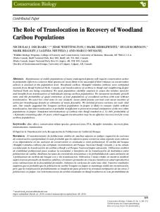
Figure 1 | Structure of phi29 connector and DNA packaging motor. a, Side view of the phi29 connector showing the acidic (red), basic (blue) and other (white) amino acids12,13,38. b, Top view of the connector showing the diameter of the narrow part and wide part of the channel. c, Illustration of the entire phi29 DNA packaging motor showing DNA translocation through the connector. d,e, A transmission electron microscope image of purified connectors with C-terminal modification before (d) and after (e) the array formation. f, Coomasie-blue stained SDS-gel showing that the modified connector is similar in size to the wild-type connector.
5 µm
5 µm
5 µm
Connectors in liposome
Connector control
Connectors
50 µm 13
15
17
19
21
23
Gradient fraction number
25
26
Pre-bleach (+)
Post-bleach (+)
30 min
70 min
(+)
(+)
(−)
(−)
Direction of sedimentation Lipid bilayer (−)
Connector (−)
Figure 2 | Images of a giant liposome containing the connector. a, Epifluorescence images of the liposome: lipid labelled with NBD-PE without connector (left); a proteoliposome reconstituted by FITC-labelled connectors (middle); a liposome mixed non-specifically with FITC-labelled connectors (right). b, Membrane filtration studies. Images of before filtration (left), the filtrate (middle) and the retentate (right) demonstrate that filtration isolated most of the free connectors. c, Separation of liposome/FITC-connector complexes by sucrose gradient sedimentation. Free connectors appeared in the top fractions whereas proteoliposomes remained in the lower fractions. Fractions 1–12 are not shown. d, Fluidity of fluorescent (red) lipid bilayer demonstrated by fluorescence recovery after photobleaching showing that the fluorescence intensity of the photobleached area (black) was gradually increased over time owing to lipid diffusion. e, Schematic showing the insertion of the connector into a planar lipid bilayer. 766
NATURE NANOTECHNOLOGY | VOL 4 | NOVEMBER 2009 | www.nature.com/naturenanotechnology © 2009 Macmillan Publishers Limited. All rights reserved.
NATURE NANOTECHNOLOGY
One pore: 69.9 pA 20 ms −150 pA
−900
100 0
−1,200
0
1
68 69 Time (min)
Current (pA)
−200 70
200 Liposome only
100 0
0 0
−1,800 Two pores: 130.9 pA 20 ms −150 pA
−2,100
3
100 101 Time (min)
102
Number of events
24
26
28 Time (min)
(−40 mV) Single connector 65 pA
12
10
20 Time (s)
30
40
20 30 Time (s)
40
−30 mV applied
−100 −200 −300
−2,400 2
400 300
−100 −200
30 mV applied
500
−1,500
Current (pA)
−100
30
0
32
10
80 Current (pA) per pore
Current (pA)
Connector only
Current (pA)
600
200
Current (pA)
ARTICLES
DOI: 10.1038/NNANO.2009.259
9
6 Double connectors 130 pA
3
40 0 −40 −80
0 0
30
60
90
120
150
−60
−30
Current jump (pA)
800
800 Insertion of an additional pore
400
Current (pA)
Current (pA)
0
One pore: Slope = 1.59 nS Three pores: Slope = 4.98 nS
0
30
60
Applied potential (mV)
Two pores: Slope = 3.40 nS
400
DNA translocation 10 µV −30 pA Unspecific blockade 80 pA 20 µV
0 One pore: Slope = 3.12 nS
−400
400 −80
−40
0
40
80
Scanning potential (mV)
−100
−50
0 50 Scanning voltage (mV)
100
Figure 3 | Conductance assays confirm the insertion of the connector into bilayer lipid membranes (BLM). a, A BLM with connector only (top) or liposomes only (bottom) in 5 mM Tris buffer/pH 7.9 and 0.5 M NaCl, with a potential of 240 mV applied. b, Addition of connector-containing proteoliposomes, with an applied potential of 240 mV, resulted in multiple insertions; this was reproduced in over 200 experiments. Insets: insertion of one connector (top) and two connectors simultaneously (bottom). c, One connector insertion at positive voltage (30 mV; top) and at negative voltage (230 mV; bottom). d, Distribution of current jump after multiple connector insertions, with a potential of 240 mV applied. e, Current–voltage relationship of single connector channels. Error bars represent three to five insertions under each applied voltage from a total of 38 inserted connectors in four individual experiments. f–g, Slopes of current traces with one, two or three connectors (f) and one connector in the presence of dsDNA (cis chamber) (g) (with ramping voltages of 2.2 mV s21). (d–f: 5 mM Tris buffer, pH 7.9 with 0.5M NaCl; g: TMS with 1M NaCl.).
configuration was verified through its ability to package the dsDNA after incorporation into the procapsid (Supplementary Fig. S2) and to assemble the resulting DNA-filled capsid into the infectious phi29 virion (Supplementary Fig. S3).
Reconstituting the connector into liposomes A procedure for reconstituting the connector into liposomes was developed by co-incubation of the connector with the lipid in the presence of sucrose. Such incubation provided an opportunity for the hydrophobic layer of the connector to interact with the hydrophobic domain of the lipid molecules. The dehydration–rehydration method42 led to the production of giant liposomes of up to 50 mm (Fig. 2a). The insertion of the connector protein into the lipid membrane was confirmed by fluorescence microscopy,
filtration assay and sedimentation analysis (Fig. 2a–c). The presence of the connector in the membrane was visible with fluorescence microscopy, which showed a clear fluorescent ring around the liposome (Fig. 2a, middle). The fluorescent ring was very similar to the liposome generated with fluorescent lipids NBD-PE (Fig. 2a, left). No fluorescent ring was observed when the fluorescently tagged connector was mixed non-specifically with the non-connector inserted liposome (Fig. 2a, right). The free connectors were removed by filtration using a membrane with a pore size of 0.45 mm or by 5–20% sucrose gradient ultracentrifugation (Fig. 2b,c).
Incorporating the connector into planar lipid membranes As none of the above experiments could distinguish between loose attachment of the connector to the bilayer surface and tight
NATURE NANOTECHNOLOGY | VOL 4 | NOVEMBER 2009 | www.nature.com/naturenanotechnology © 2009 Macmillan Publishers Limited. All rights reserved.
767
ARTICLES
NATURE NANOTECHNOLOGY
DOI: 10.1038/NNANO.2009.259
Table 1 | Comparison of single-channel conductance from the GP10 connector and a-haemolysin. Proteins Connector a-HL Ratio (connector/a-HL)
Pore diameter (nm)
Cross-section area (nm2)
3.6 1.530 2.4
10.2 1.8 5.7
Conductance (nS per pore)* 0.5 M NaCl 1 M KCl 1.57+0.16 4.84+0.15 0.31+0.05† 0.94+0.01‡ 5.1 5.1
*The data for connector conductance at 0.5 M NaCl and 1M KCl were obtained from a total of 38 and 36 insertions, respectively. The data for a-HL conductance at both 0.5 M NaCl and 1 M KCl were from a total of four insertions. † Conductance of a-HL at 1 M NaCl has been reported to be 0.68 nS per pore46. ‡ Conductance of a-HL at 1 M KCl has been reported to be 0.80 (ref. 47) or 1.0 (ref. 27) nS per pore.
incorporation of it into the bilayer membrane to form a channel, a single channel conductance assay was performed. Results showed that direct incubation of the connector with liposomes or with a planar lipid bilayer did not lead to channel formation in the bilayer membrane (Fig. 3a). Connector insertion into the bilayer only occurred when the connector-reconstituted proteoliposomes were fused into the bilayer (Fig. 3b,c). The channel insertion was observed through a discrete stepwise increase in conductance as shown in a continuous current trace (Fig. 3b), under either a positive or negative transmembrane voltage (Fig. 3c). Normally, the insertion of one connector into the bilayer results in an increase in the current of approximately 65 pA (equivalent to 1.6 nS) at a potential of 240 mV in 5 mM Tris (pH 7.9)/0.5 M NaCl. Occasionally a 130.9 pA jump, attributed to insertion of two connectors, was also observed (Fig. 3d). Similar results were obtained when the channel conductance was measured in TMS/1 M NaCl (Supplementary Fig. S4). In this case, the occurrence of simultaneous insertion of two connectors and three connectors was 4.7% and 1.9%, respectively. For conductance measurements, a plot of the current–voltage curve was obtained under different voltages (Fig. 3e). The average conductance for a single pore was 1.57+0.16 nS per pore (a total of 38 inserted connectors) in 5 mM Tris/0.5 M NaCl (Fig. 3e), and 3.21+0.51 nS per pore (a total of 213 inserted connectors) in TMS/1 M NaCl buffer (Supplementary Fig. S4). As a comparison, the conductance measurements were also performed for connector channels under a ramp voltage (Fig. 3f,g). The slopes from the fitted curves representing the conductance of formed channels in 5 mM Tris/0.5 M NaCl were 1.59 nS for a single pore, 3.40 nS for two pores, and 4.98 nS for three pores. When the NaCl concentration was increased to 1 M (TMS buffer with 1 M NaCl), the slope of the curve was 3.12 nS for a single pore. A buffer of 5 mM HEPES/1 M KCl was also used for conductance measurements (Table 1). The channel conductance of the connector was compared with that of a-HL using solutions of different ionic strength (Table 1). It has been reported that the diameter of the narrow end of the connector channel is 3.6 nm, whereas the channel formed by a-HL has a diameter of only 1.5 nm30. Therefore, the ratio of the cross-sectional area of the channels between the connector and a-HL is 5.7. The ratio of measured conductance of the connector to a-HL is 5.1 (Table 1). As the conductance of a channel is proportional to its cross-sectional area, it can be concluded that the cross-sectional area of the connector in the buffer solutions was approximately 5.1-fold greater than that of a-HL, which compares well with the ratio of cross-sectional areas from the crystal data of both proteins. Moreover, compared with other transmembrane proteins or ion channel proteins with larger channels, such as Streptolysin43, Kir44, VDAC45 and bacterial porins32, the connector channel has additional advantages. For example, the connector channels were stable and did not show voltage gating under the reported conditions. The channel conductance was uniform, demonstrating a linear response to applied voltages between 2100 mV and 100 mV (Fig. 3f,g). 768
Translocation of double-stranded DNA Both linear and circular plasmid Cx43 DNA (5.5 kilobase pairs) were used to examine the translocation of dsDNA through the connector channel. In the case of the linear DNA plasmid, DNA translocation induced numerous current blockades, which led to the current jump of single connector insertion to be transiently reduced by 25–45% (Fig. 4c). Similar results were also found in translocation experiments of a 35-bp dsDNA (Supplementary Fig. S5). However, when the linear Cx43 was added to the cis chamber, no such blockades were observed until the voltage was switched to positive potential (Fig. 3g). The short-lived blockades could be attributed to the occurrence of DNA translocations. In contrast, in the absence of DNA, the current trace was quiescent (Fig. 4a and Supplementary Fig. S5b). Occasionally, unspecific blockades were observed with a minimum detectable time. These unspecific blockades occurred rarely compared with DNA translocation events. They were usually characterized by a detectable time that was very close to the limit of sampling frequency (Fig. 4b and Fig. 3g). When circular plasmid dsDNA Cx43 was used, no translocation of the circular plasmid was observed (Fig. 4b, upper left). Interestingly, when the same amount of circular plasmid digested by DNase I was added to the chamber, a burst of transient blockades occurred. (Fig. 4b, lower left). The same results were also observed when the linear Cx43 digested by DNase I was used (Fig. 4b, lower right). All the above results confirmed that only the linear dsDNA passed through the connector channels. Occasionally, we also witnessed blockade events in the range of 5–15% (Fig. 4c, right) with a dwell time from several to hundreds of milliseconds. The events were attributed to non-specific blockades other than DNA translocation because they were found to occur in the absence of DNA (Supplementary Fig. S5b). The non-specific blockade events could be due to interactions of connector pores with lipids or lipid micelles because their occurrence increased after the addition of more liposomes to the chamber (data not shown). The occurrence of the non-specific blockades is minimized when diluted connector reconstituted liposomes are used and/or a lower transmembrane voltage is applied (Fig. 4c, left). Interestingly, we occasionally observed simultaneous blockade events (inset in Fig. 4b, upper right and Supplementary Fig. S5a). These events were recorded under multiple pore conditions. A continuous current trace recording events before and after addition of DNA was also shown (Supplementary Fig. S5b). On one occasion, a burst of DNA blockades was observed after the insertion of a third connector. In comparison, when DNA was premixed with buffer before connector insertion, the DNA blockades were observed immediately after the first insertion occurred (Supplementary Fig. S5a). This result indicates the lack of a stirring facility in the DNA chamber leading to a delay in DNA translocation. The blockade rates were affected by two factors: DNA concentration and transmembrane voltage. In the presence of 45 pM DNA under three connector insertions, the blockade rate was approximately 0.8–1 blockades per second (Fig. 4b, upper right). Under the same number of insertions, when 4 mM of DNA was placed in the chamber, the blockade rate was approximately
NATURE NANOTECHNOLOGY | VOL 4 | NOVEMBER 2009 | www.nature.com/naturenanotechnology © 2009 Macmillan Publishers Limited. All rights reserved.
NATURE NANOTECHNOLOGY
ARTICLES
DOI: 10.1038/NNANO.2009.259
Current (pA)
No DNA added 0 One channel inserted
−100 −200 0
5
10
15
20
25
30
35
Time (s) Circular DNA
Current (pA)
Dwell time: 15 ms
A non-specific spike
−500
Without DNase digestion
Linear DNA
20 ms −50 pA
−600
20 ms −50 pA
5s
2 events
1 event
−100 pA −700 −800
0
10
20 30 Time (s)
40
10
50
20
30 Time (s)
40
30 µs −50 pA
Current (pA)
With DNase digestion
DNA translocation events
5s
10 ms −50 pA
−500
−100 pA
3 blockades
−600
2 blockades
−700 1 blockade −800 0
10
20
30 Time (s)
50
20
100
38%
30
40 Time (s)
−75 mV applied
−40 mV applied 200
40
−75 mV applied
−40 mV applied
36%
30
80
25 30
60
40
Number of events
100
Number of events
Number of events
Number of events
150
20
20
15
10
10
50
20
0
5
0 10
20
30
40
Blockade (%)
50
0 0
10
20
30
40
Blockade (%)
50
0 0
20 40 60 80 100 Dwell time (ms)
0
20 40 60 80 100 Dwell time (ms)
Figure 4 | Translocation of dsDNA through connector channels in a BLM. a, A typical current trace when the BLM contains a connector but no DNA (control), in TMS buffer and 1 M NaCl, with an applied potential of 275 mV. b, Representative blockades caused by 45 pM double-stranded circular and linear plasmid DNA without and with DNase digestion in a BLM containing three connectors. c,d, Histograms showing the percentage of current blockade (c) and dwell time (d) caused by linear plasmid dsDNA under 240 mV (left) and 275 mV (right). The DNA translocation experiment was repeated 45 times.
5–5.8 blockades per second (Supplementary Fig. 5a,b). For the linear Cx43 DNA, the blockade rate increased as the ramping voltage was applied (Fig. 3g). To calculate the dwell time (tp) for DNA translocation events, we grouped blockade episodes greater than 32% as this percentage
of blockade seemed consistent with the ratio of the cross-sectional area between dsDNA and the pore. A histogram of these events can be seen in Fig. 4d. It should also be noted that 6 (under 275 mV) and 20 (under 240 mV) individual outlying events scattered between 120 ms to 9,800 ms were not included in
NATURE NANOTECHNOLOGY | VOL 4 | NOVEMBER 2009 | www.nature.com/naturenanotechnology © 2009 Macmillan Publishers Limited. All rights reserved.
769
1,500 5
Threshold 500 0 0
Threshold cycle (CT)
3 × 10 3 × 10⁴ 3 3 × 10 3 × 10² 3 × 101
1,000
35
5
10
15
20 Cycle
25
30
35
40
y = −3.879 x + 41.403 R2 = 0.999
30 25 20 1
2 3 4 5 Log DNA molecules per reaction of 25 uL
6
Total number of DNA molecules passing through one channel
NATURE NANOTECHNOLOGY
DOI: 10.1038/NNANO.2009.259
10,000 With connectors (N = 9) 8,000 6,000 4,000 2,000
Total number of DNA molecules passing through one channel
PCR base line subtracted (CF RFU)
ARTICLES
0
Without connector (N = 4)
3
0 0
30
60
90
Time (min)
Figure 5 | Quantitative PCR analysis of DNA translocation events. a, Q-PCR amplification curves of the dilution series run in triplicate. b, A standard curve with threshold cycle plotted against the log of the starting quantity of template for each dilution. c, Quantitative analysis of the total number of DNA molecules passing through one of the connectors in the lipid membrane from the trans chamber to the cis chamber (top). Negative controls (bottom) were carried out under the same conditions but without connectors. The error bars represent standard deviations of the mean from nine independent experiments and four negative control experiments.
the graph for clarity. The dwell time distribution under 240 mV seemed broader than that under 275 mV. The average dwell time for DNA blockades under 275 mV and under 240 mV was 9.2 ms and 22.1 ms, respectively (note: only the events less than 50 ms under 240 mV were used for the calculation). As a comparison, the distribution of dwell time for the 35-bp dsDNA are also included (Supplementary Fig. S6b,c). The average of the dwell times in this case was 0.53 ms. Therefore, it can be concluded that the dwell time of DNA translocation was affected by applied voltage and the size of DNA. To verify the passage of dsDNA through the connector channels, quantitative polymerase chain reaction (PCR) (Q-PCR) was used to quantify the translocation of 141-bp DNA under a constant voltage. DNA was added to the trans side and samples were taken from the cis side for quantification at 30 minute intervals. For comparison, control experiments were performed in the absence of connectors (Fig. 5c). Experiments with connector insertions in bilayer lipid membranes (BLMs) showed an increase in the number of DNA molecules in the cis chamber over time (N ¼ 9 experiments). In contrast, in the absence of connectors the number of DNA molecules in the cis chamber remained undetectable over the 90-minute time course (N ¼ 4 experiments). Moreover, the DNA translocation rate was affected by the number of inserted connectors (Supplementary Fig. S7a). To verify that the increase of the DNA copy number in the cis chamber was due to DNA translocation through the channels rather than membrane leakage, three additional experiments were carried out under the conditions of known leakage of BLM or partitions. When leaking occurred, the copy number of DNA per ml of solution in the cis-chamber was approximately 104–105-fold higher than those experiments without leakage (Supplementary Fig. S7b).
Conclusion Herein, an engineered form of the GP10 connector has been incorporated into a lipid bilayer, forming a highly conductive nanopore. By evaluating the changes of the conductance and performing Q-PCR analysis, the translocation of the linear 5.5-kilobase plasmid DNA, 141-bp DNA and 35-bp DNA through the channel 770
was confirmed. This work provides a system or a tool for future electrophysiology studies of the phi29 DNA packaging motor. Furthermore, the connector is a biological nanopore that is extremely reproducible and easily engineered, making it suitable for future biomedical and nanotechnological applications.
Methods Preparation of giant lipid vesicles containing the reengineered connector. To prepare the fluorescent giant lipid vesicles, 1 ml of 1 mg ml21 1,2-dioleoyl-snglycero-3-phosphocholine (DOPC) or 1,2-diphytanoyl-sn-glycero-3phosphocholine (DPhPC) and 1% (molar ratio) N-(7-nitrobenz-2-oxa-1,3-diazol-4yl)-1,2-dihexadecanoyl-sn-glycero-3-phosphoethanolamine, triethylammonium salt (NBD-PE) were mixed in a vial. Chloroform was evaporated by a gentle stream of nitrogen gas, and the lipid vial was further dried in a desiccator overnight. To rehydrate the lipid film, 2 ml of 200–300 mM sucrose was used to bud vesicles off the glass and into the solution. The vial was then covered with parafilm and stored overnight. An aliquot was taken from the middle of the solution and then transferred into a Petri dish. After settling, the vesicles were observed with epi-fluorescence microscopy (Fig. 2a). Incorporation of the connector into giant vesicles was accomplished as described above, except the NBD-PE was omitted. A volume of 100 ml of fluorescein isothiocyanate (FITC)-labelled reengineered connectors was added to the above dehydrated lipid with a final lipid:connector molar ratio of 75:1 (or as low as 4,000:1 to 16,000:1 for BLM experiments) (Fig. 2a, middle). Insertion of the connector into a planar bilayer lipid membrane. A two-step approach was used to incorporate the connector into the planar BLM. The first step was the preparation of unilamellar lipid vesicles containing the reengineered connector as described above. The next step was to fuse the extruded liposome into a planar BLM (Fig. 2e). The fluidity of the lipid bilayer was demonstrated by fluorescence recovery after photobleaching (Fig. 2d). An excitation light was focused continuously on the bilayer to bleach the dye. The photobleached area appeared dark. But after the light was turned off, it gradually recovered owing to the diffusion of the fluorescent lipid. A standard BLM chamber (BCH-1A from Eastern Sci LLC) was used to form horizontal BLMs. A thin Teflon film with an aperture of 70–120 mm (TP-01 from Easter Sci LLC) or 180–250 mm (TP-02 from Easter Sci LLC) in diameter was used as a partition to separate the chamber into cis (working volume 250 ml) and trans (working volume 2.5 ml) compartments. After the aperture was pre-painted with 0.5 ml 3% (w/v) DPhPC n-decane solution twice to ensure the complete coating of the entire edge of the aperture, these compartments were filled with conducting buffers (5 mM Tris/pH 7.9, TMS or 5 mM HEPES/pH 7.9, with varying concentrations of NaCl or KCl). Formation of the bilayer membrane on the partition is a key step for connector insertion into the bilayer (Fig. 2e). Considering all experiments, the occurrence of
NATURE NANOTECHNOLOGY | VOL 4 | NOVEMBER 2009 | www.nature.com/naturenanotechnology © 2009 Macmillan Publishers Limited. All rights reserved.
NATURE NANOTECHNOLOGY
DOI: 10.1038/NNANO.2009.259
successful connector insertions was about 47–83%, which varied from person to person based on BLM experience and the quality of prepared proteoliposomes. So far, we have carried out a total of 280 separate BLM experiments in which successful connector insertions were found. For single conductance measurements, the giant liposome/connector complex prepared earlier must be extruded using a polycarbonate membrane with pore sizes of 200 nm or 400 nm to generate small unilamellar liposomes. This liposome stock solution was further diluted by 10–20-fold for the BLM experiments before use. For insertion of connectors, 0.5-2.0 ml of the diluted liposome solution was loaded into the cis chamber. Conductance was measured in two ways: the first was derived at specific but constant holding potentials, and the second from the slope of the current trace induced by a scanning potential starting at 2100 mV and ramping to 100 mV after incorporation of GP10 connector into the lipid membrane (Fig. 3f,g). Q-PCR analysis. For Q-PCR analysis, the connector/liposome complexes were added to the cis side (working volume 500 ml). 141-bp DNA was added to the trans side with a final concentration of 25 nM. As a negative control, the DNA was added without the addition of connector/liposome complexes. A potential of 295 mV was applied and samples were collected from the cis side at 30 min intervals for Q-PCR analysis. DNA concentration was determined by a DU530 UV/vis spectrometer (Beckman Coulter). Absolute quantification was used to determine the copy number of DNA in samples collected. Standard curves were constructed using the 141-bp DNA with 10-fold dilution of known concentration (Fig. 5a,b). Each dilution was assayed in triplicate. iQTM SYBR Green Supermix (Bio-Rad) was used for the Q-PCR reaction. Q-PCR was carried out in the iCycler iQTM multicolor real-time PCR detection system (Bio-Rad). The sequences for forward and reverse primers corresponding to the DNA template were 50 -TAA TAC GAC TCA CTA TTA GAA CGG CAT CAA GGT GAA CTC AAG ATT TTG TAT GTT GGG GAT TA-30 and 50 -AAG AAC GGC ATC AAG GTG AAC TTC AAG ATA ATT GAC AGC AGG CAA TCA AC-30 , respectively (purchased from IDT). See also Supplementary Information.
Received 19 February 2009; accepted 4 August 2009; published online 27 September 2009
References 1. Black, L. W. DNA packaging in dsDNA bacteriophages. Ann. Rev. Microbiol. 43, 267–292 (1989). 2. Guo, P. Introduction: Principles, perspectives, and potential applications in viral assembly. Semin. Virol. 5, 1–3 (1994). 3. Guo, P. X. & Lee, T. J. Viral nanomotors for packaging of dsDNA and dsRNA. Mol. Microbiol. 64, 886–903 (2007). 4. Rao, V. B. & Feiss, M. The bacteriophage DNA packaging motor. Annu. Rev. Genet. 42, 647–681 (2008). 5. Guo, P., Peterson, C. & Anderson, D. Prohead and DNA-gp3-dependent ATPase activity of the DNA packaging protein gp16 of bacteriophage f29. J. Mol. Biol. 197, 229–236 (1987). 6. Chemla, Y. R. et al. Mechanism of force generation of a viral DNA packaging motor. Cell 122, 683–692 (2005). 7. Hwang, Y., Catalano, C. E. & Feiss, M. Kinetic and mutational dissection of the two ATPase activities of terminase, the DNA packaging enzyme of bacteriophage lambda. Biochemistry 35, 2796–2803 (1996). 8. Sabanayagam, C. R., Oram, M., Lakowicz, J. R. & Black, L. W. Viral DNA packaging studied by fluorescence correlation spectroscopy. Biophys. J. 93, L17–L19 (2007). 9. Moffitt, J. R. et al. Intersubunit coordination in a homomeric ring ATPase. Nature 457, 446–450 (2009). 10. Kochan, J., Carrascosa, J. L. & Murialdo, H. Bacteriophage lambda preconnectors: purification and structure. J. Mol. Biol. 174, 433–447 (1984). 11. Rishovd, S., Holzenburg, A., Johansen, B. V. & Lindqvist, B. H. Bacteriophage P2 and P4 morphogenesis: structure and function of the connector. Virology 245, 11–17 (1998). 12. Simpson, A. A. et al. Structure determination of the head-tail connector of bacteriophage phi29. Acta Cryst. D57, 1260–1269 (2001). 13. Guasch, A. et al. Detailed architecture of a DNA translocating machine: the high- resolution structure of the bacteriophage phi29 connector particle. J. Mol. Biol. 315, 663–676 (2002). 14. Agirrezabala, X. et al. Structure of the connector of bacteriophage T7 at 8A resolution: structural homologies of a basic component of a DNA translocating machinery. J. Mol Biol. 347, 895–902 (2005). 15. Bazinet, C. & King, J. The DNA translocation vertex of dsDNA bacteriophages. Ann. Rev. Microbiol. 39, 109–129 (1985). 16. Guo, P., Grimes, S. & Anderson, D. A defined system for in vitro packaging of DNA-gp3 of the Bacillus subtilis bacteriophage phi29. Proc. Natl Acad. Sci. USA 83, 3505–3509 (1986). 17. Guo, P., Erickson, S. & Anderson, D. A small viral RNA is required for in vitro packaging of bacteriophage phi29 DNA. Science 236, 690–694 (1987).
ARTICLES
18. Guo, P. et al. Inter-RNA interaction of phage phi29 pRNA to form a hexameric complex for viral DNA transportation. Mol. Cell 2, 149–155 (1998). 19. Zhang, F. et al. Function of hexameric RNA in packaging of bacteriophage phi29 DNA in vitro. Mol. Cell 2, 141–147 (1998). 20. Shu, D., Zhang, H., Jin, J. & Guo, P. Counting of six pRNAs of phi29 DNApackaging motor with customized single molecule dual-view system. EMBO J. 26, 527–537 (2007). 21. Thieffry, M., Chich, J. F., Goldschmidt, D. & Henry, J. P. Incorporation in lipid bilayers of a large conductance cationic channel from mitochondrialmembranes. EMBO J. 7, 1449–1454 (1988). 22. Hinnah, S. C. et al. The chloroplast protein import channel Toc75: Pore properties and interaction with transit peptides. Biophys. J. 83, 899–911 (2002). 23. Alcayaga, C., Venegas, R., Carrasco, A. & Wolff, D. Ion channels from the Bacillus subtilis plasma-membrane incorporated into planar lipid bilayers. FEBS Lett. 311, 246–250 (1992). 24. Benz, R., Schmid, A., Nakae, T. & Vosscherperkeuter, G. H. Pore formation by LamB of Escherichia coli in lipid bilayer membranes. J. Bacteriol. 165, 978–986 (1986). 25. Movileanu, L., Howorka, S., Braha, O. & Bayley, H. Detecting protein analytes that modulate transmembrane movement of a polymer chain within a single protein pore. Nature Biotechnol. 18, 1091–1095 (2000). 26. Kasianowicz, J. J., Brandin, E., Branton, D. & Deamer, D. W. Characterization of individual polynucleotide molecules using a membrane channel. Proc. Natl Acad. Sci. USA 93, 13770–13773 (1996). 27. Vercoutere, W. et al. Rapid discrimination among individual DNA hairpin molecules at single-nucleotide resolution using an ion channel. Nat. Biotechnol. 19, 248–252 (2001). 28. Vercoutere, W. A. et al. Discrimination among individual Watson-Crick base pairs at the termini of single DNA hairpin molecules. Nucleic Acids Res. 31, 1311–1318 (2003). 29. Howorka, S., Cheley, S. & Bayley, H. Sequence-specific detection of individual DNA strands using engineered nanopores. Nat. Biotechnol. 19, 636–639 (2001). 30. Song, L. et al. Structure of Staphylococcal alpha-hemolysin, a heptameric transmembrane pore. Science 274, 1859–1865 (1996). 31. Butler, T. Z. et al. Single-molecule DNA detection with an engineered MspA protein nanopore. Proc. Natl Acad. Sci. USA 105, 20647–20652 (2008). 32. Szabo, I., Tombola, F., Martinucci, S. & Zoratti, M. DNA interacts with Bacillus subtilis mechano-sensitive channels in native membrane patches. Cell Physiol. Biochem. 12, 127–134 (2002). 33. Mobasheri, H. & Lea, E. J. Biophysics of gating phenomena in voltage-dependent OmpC mutant porin channels (R74C and R37C) of Escherichia coli outer membranes. Eur. Biophys. J. 31, 389–399 (2002). 34. Carneiro, C. M. et al. Probing the volume changes during voltage gating of Porin 31BM channel with nonelectrolyte polymers. Biochim. Biophys. Acta 1612, 144–153 (2003). 35. Wang, H. & Branton, D. Nanopores with a spark for single-molecule detection. Nature Biotechnol. 19, 622–623 (2001). 36. Iqbal, S. M., Akin, D. & Bashir, R. Solid-state nanopore channels with DNA selectivity. Nature Nanotech. 2, 243–248 (2007). 37. Cai, Y., Xiao, F. & Guo, P. N- or C-terminal alterations of motor protein gp10 of bacterial virus phi29 on procapsid assembly, pRNA binding and DNA packaging. Nanomedicine 4, 8–18 (2008). 38. Guo, Y., Blocker, F., Xiao, F. & Guo, P. Construction and 3-D computer modeling of connector arrays with tetragonal to decagonal transition induced by pRNA of phi29 DNA-packaging motor. J. Nanosci. Nanotechnol. 5, 856–863 (2005). 39. Ibanez, C., Garcia, J. A., Carrascosa, J. L. & Salas, M. Overproduction and purification of the connector protein of Bacillus subtilis phage f29. Nucleic Acids Res. 12, 2351–2365 (1984). 40. Robinson, M. A. et al. Affinity of molecular interactions in the bacteriophage phi29 DNA packaging motor. Nucleic Acids Res. 34, 2698–2709 (2006). 41. Xiao, F. et al. Fabrication of massive sheets of single layer patterned arrays using reengineered Phi29 motor dodecamer. ACS Nano 3, 100–107 (2009). 42. Lasic, D. D. Liposomes in Gene Delivery (CRC Press, 1997). 43. Gilbert, R. J. C. et al. Two structural transitions in membrane pore formation by Pneumolysin, the pore-forming toxin of Streptococcus pneumoniae. Cell 97, 647–655 (1999). 44. Lopatin, A. N. & Nichols, C. G. [K þ ] dependence of open-channel conductance in cloned inward rectifier potassium channels (IRK1, Kir2.1). Biophys. J. 71, 682–694 (1996). 45. Szabo, I. et al. Double-stranded DNA can be translocated across a planar membrane containing purified mitochondrial porin. FASEB J. 12, 495–502 (1998). 46. Braha, O. et al. Designed protein pores as components for biosensors. Chem. Biol. 4, 497–505 (1997). 47. Wong, D., Jeon, T. J. & Schmidt, J. Single molecule measurements of channel proteins incorporated into biomimetic polymer membranes. Nanotechnology 17, 3710–3717 (2006).
NATURE NANOTECHNOLOGY | VOL 4 | NOVEMBER 2009 | www.nature.com/naturenanotechnology © 2009 Macmillan Publishers Limited. All rights reserved.
771
ARTICLES
NATURE NANOTECHNOLOGY
Acknowledgements We thank R. Zhang for Q-PCR analysis, J. Schmidt and L. Gu for a-haemolysin proteins; F. Haque for BLM experiments; Y. Shu for DNA preparation, C. Brokamp for advice on BLM, N. Stonehouse, Y. Cai and F. Xiao for recombinant connectors; A. Butti for fluorescence recovery after photobleaching, J. Meller and A. Herr for connector amphiphilicity analysis; A. Vonderheide for manuscript modification. The research was supported by NIH Nanomedicine Development Center: Phi29 DNA Packaging Motor for Nanomedicine, through the NIH Roadmap for Medical Research (PN2 EY 018230) (P.G.) and NIH Grant GM59944 (P.G.). P.G. is a co-founder of Kylin Therapeutics.
Author contributions P.G. designed and led the project in collaboration with C.M. in single pore measurements. V.S. (when she was a postdoctoral researcher with P.G. at Purdue University), J.G. and P.J. developed protocols for incorporating the connector into the membrane of liposome for
772
DOI: 10.1038/NNANO.2009.259
image characterization and BLM experiments. P.J contributed the data for conductance measurements and Q-PCR. P.J. and J.G. contributed the data for the dsDNA translocation experiment. P.J. and J.G. performed all the data analysis. D.W. provided fusion procedure and technical training for BLM experiment. T.L. contributed materials and participated in PCR analysis. P.G. prepared the first draft of the manuscript with the input of C.M.. P.J., J.G., D.W. and T.L. assisted with the manuscript revision.
Additional information Supplementary information accompanies this paper at www.nature.com/ naturenanotechnology. The authors declare competing financial interests: details accompany the full-text HTML version of the paper at www.nature.com/naturenanotechnology. Reprints and permission information is available online at http://npg.nature.com/ reprintsandpermissions/. Correspondence and requests for materials should be addressed to P.G.
NATURE NANOTECHNOLOGY | VOL 4 | NOVEMBER 2009 | www.nature.com/naturenanotechnology © 2009 Macmillan Publishers Limited. All rights reserved.