Noname manuscript No. (will be inserted by the editor)
Throughput Maximization in Cognitive Radio System with Transmission Probability Scheduling and Traffic Pattern Prediction Yang Cao ⋅ Daiming Qu ⋅ Tao Jiang
Received: date / Accepted: date
Abstract In this paper, we propose a novel transmission probability scheduling (TPS) scheme for opportunistic spectrum access based cognitive radio system, in which secondary user (SU) aims to maximize its throughput when the collision probability perceived by primary user (PU) is constrained under required threshold. Particularly, we first study the maximum achievable SU throughput when distribution of the PU idle period is known and the spectrum sensing is perfect. When the spectrum sensing is imperfect, we thoroughly quantify the impact of sensing errors on the SU performance. Furthermore, when the traffic pattern of the PU and its parameters are unknown, we propose a predictor based on hidden Markov model (HMM) to predict the future PU state. Extensive simulations are conducted and show that the proposed TPS scheme with the HMM-based predictor can achieve a reasonably high SU throughput under the PU collision probability constraint even when the sensing errors are serve.
This work was funded by the National Natural Science Foundation of China under Grant 61172052 and Grant 60872008, the Program for New Century Excellent Talents in University of China under Grant NCET-08-0217, the Project-sponsored by SRF for ROCS, SEM, the National & Major Project with Grant 2012ZX03003004. Yang Cao Daiming Qu Tao Jiang ( ) Dept. of Electronics and Info. Engineering, Wuhan National Laboratory for Optoelectronics, Huazhong Univ. of Science & Technology, Wuhan, China E-mail:
[email protected] Yang Cao E-mail:
[email protected] Daiming Qu E-mail:
[email protected]
Keywords Opportunistic spectrum access ⋅ throughput maximization ⋅ transmission probability scheduling ⋅ hidden Markov model ⋅ cognitive radio system
1 Introduction Recently, dynamic spectrum access (DSA) has been proposed to improve the utilization efficiency of the licensed spectrum. A thorough introduction of existing DSA technologies was given in [1], where opportunistic spectrum access (OSA) is emphasized. In an OSA-based cognitive radio system (CRS), a spectrum hole is defined as frequency band licensed by a primary user (PU) that is not being utilized at a particular time and geographical location [2]. To utilize these spectrum holes with required protection over the PUs in the same frequency band, secondary users (SUs) have to adopt strict constraints on the resulting interference. For example, for the packet-based PUs, an OSA-based CRS usually constrains the probability of collision with the PU packet to be under a predefined threshold [3] - [5]. Therefore, it is critical how to maximize the SU throughput under a certain PU collision probability constraint. Specifically, one effective approach is based on optimal channel selection in multi-channel systems. In [3], authors proposed an optimal channel selection strategy based on the constrained Markov decision process (CMDP) to maximize the SU throughput under a collision probability constraint over the packets of the SU and the PU. In [4], an optimal sensing with access strategy was proposed to improve the SU throughput, which is based on the partially observable Markov decision process (POMDP). In [5], the authors considered how to make a joint design of the spectrum sensor in the
2
physical layer and the access strategy in the MAC layer. In [6], optimal strategies were proposed to maximize the total expected data rate of the SU without a priori knowledge of the PU channel statistics. A method to suppress sidelobes of the orthogonal frequency division multiplexing (OFDM) signals was proposed, which enables the OFDM-based secondary users to utilize noncontiguous spectrum holes over multi-channels [7]. Besides the channel selection strategies in multichannel CRS, the throughput maximization problem has also been addressed in single-channel OSA-based CRS. In [8], multiple antennas are exploited at the SU transmitter to achieve optimal tradeoff between throughput maximization and interference avoidance. In [9], the structure of sensing and transmission for the SU is optimized to maximize its throughput under the consideration of sensing overhead. In [10], it is shown that the SU throughput can be maximized by adopting an optimal sensing time. Authors of [11] further considered the energy constraint at the SU to maximize the SU throughput. In [12], a joint design between frame duration/sensing time in PHY and random access scheme in the MAC layer was presented to maximize the SU throughput. The aforementioned schemes require a priori knowledge of the PU traffic pattern. In [13], authors proposed an adaptive SU transmission scheme to maximize the SU throughput under the PU collision probability constraint with the assumption that the PU traffic pattern is unknown to the SU. However, when the parameters of the PU traffic pattern are time-varing, the performance of this scheme is not so satisfactory. In this paper, we propose a novel OSA scheme that exploits instantaneous spectrum opportunities on a single channel that is licensed to a packet-based PU. The proposed scheme schedules the transmission probabilities of the SU during an idle period of the PU, which spans over some SU slots. Our aim is to maximize the throughput/spectrum utilization efficiency of the OSAbased CRS with the constraint on the packet collision probability between the SU and the PU. The contributions of this paper are summarized as follows – When the spectrum sensing at the SU is perfect and the PU traffic pattern is known to the SU, we propose a transmission probability scheduling (TPS) scheme that maximizes the SU throughput under the PU collision probability constraint. Simulation results show that the throughput improvement can be as high as 100% if the idle period of the PU follows the hyper-Erlang distribution [16]. – When the spectrum sensing at the SU is imperfect, we quantify the impact of sensing errors on the SU performance with the proposed TPS scheme.
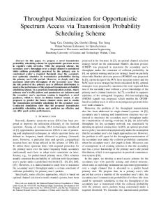
Fig. 1 Spectrum holes in an OSA-based CRS.
– When the PU traffic pattern is unknown to the SU and time-varying, along with the errors in spectrum sensing, we develop a method to predict the future PU states by learning past periodic sensing results based on the hidden Markov model (HMM), and use these predictions in the proposed TPS scheme. The rest of the paper is organized as follows. Section 2 presents the system model. In Section 3, we propose a novel OSA scheme to maximize the SU throughput. Then, in Section 4, we study the maximum achievable throughput of the SU that adopts the proposed scheme under different distributions of the PU idle period. In Section 5, the impact of sensing errors on the SU performance with the proposed scheme is analyzed and quantified. In Section 6, when the PU traffic pattern and some PU parameters are unknown and the spectrum sensing at the SU is imperfect, we develop a hidden Markov model based predictor to predict the future PU states. Simulation results are given in Section 7, followed by conclusions in Section 8. 2 System Model As depicted in Fig. 1, the SU exploits spectrum holes while limits the interference perceived by the PU who works on the same channel in an OSA-based CRS. The PU has the priority to access the channel and it is not responsible for any sort of notification to the SU for its transmission. We assume that the locations of the PU transmitters/receivers and the SU transmitters/receivers disperse in the same region with limited area, i.e., the delay for packet transmission is negligible. Suppose that the PU traffic pattern follows an ON/OFF model (also adopted in [13]), in which its state becomes busy (“ON”, packet transmission) or idle (“OFF”, idle period/spectrum hole) alternatively. Thus, the SU should target at a temporal utilization of the spectrum hole and vacate the channel as quickly as possible when the PU state turns from idle to busy. Suppose SU is equipped with a half-duplex transceiver, i.e., during data transmission, the SU is no longer capable of sensing the channel. To schedule sensing and transmission periodically, the SU employs a slotted communication protocol [3] as depicted in Fig. 2, in which 𝐿
3
Spectrum Hole Identified
Missed Detection
False Alarm Type-I Collision
Type-II Collision busy
step 1
idle
step 2
step i
step N
td
Time
L PU Packet
Sensing SubSlot of SU
Data Sub-Slot of SU
slot k-1
Slot Boundary
slot k
PU Packet
Time
slot k+1
Sensing SubSlot of SU
Slot Boundary
Fig. 2 The structure of the SU transmission.
Fig. 3 Spectrum hole identification.
denotes the time duration for one SU slot. At the beginning of each slot, SU turns off the transmitter and sense the channel during the sensing sub-slot that lasts for 𝐿𝑠 ; when the duration of the sensing sub-slot is over, the SU could transmit data during the following data subslot that lasts for 𝐿𝑑 , 𝐿 = 𝐿𝑠 + 𝐿𝑑 . Generally, 𝐿𝑠 ≪ 𝐿𝑑 . To protect the PU packets, the SU is allowed to access the channel only when current sensing result shows that the channel is not occupied by the PU. For an OSA-based CRS, strict interference constraint is usually imposed on the SU to ensure that the interference perceived by the PU lies below a predefined threshold. Due to the fact that the SU could not sense the channel during data transmission, a sensing result that shows the PU is idle during the current sensing sub-slots does not mean the idle state of the PU would remain during the following data sub-slot. As a result, collision occurs if the PU accesses the channel when the SU is transmitting during the data sub-slot, consequently resulting in the packets loss for both PU and SU. If the spectrum sensing at the SU is perfect, i.e., the probability of sensing errors approaches zero, collisions could only occur at the head of a PU packet, which is denoted as type-I collisions; otherwise, collisions may happen during the PU transmission due to the missed detection, which is denoted as type-II collisions, as shown in Fig. 2. To protect the PU packets from excessive collisions, we define the average ratio of collisions in all primary packets during a certain time duration 𝑈 as a measure of the interference caused by the SU from the PU’s perspective (similar definition of interference metric is also adopted in [13]), denoted the average packet collision ratio (APCR) as 𝑅C , i.e.,
trum hole. In this paper, we employ the spectrum hole utilization efficiency as a measure of the throughput for the OSA-based CRS (similar definition of the SU throughput is also adopted in [13]). Therefore, the normalized throughput of the SU is defined as
𝑅C = lim
𝑈 →+∞
𝑁C , 𝑁P
(1)
where 𝑁P is the number of the PU packets during 𝑈 , and 𝑁C is the number of collisions during 𝑈 . In this paper, we aim to constrain 𝑅C to be below a predefined threshold 𝑅TH . In other words, the PU could tolerate the interference and it can safely transmit data when 𝑅C ≤ 𝑅TH . Moreover, we concern about the SU throughput, which depends on the utilization efficiency of the spec-
𝑇 = lim
𝑈 →+∞
𝑁S , 𝑁IDLE
(2)
where 𝑁S is the total number of data sub-slots that are successfully utilized by the SU in the PU idle period during 𝑈 , and 𝑁IDLE is the total number of available data sub-slots in the PU idle period during 𝑈 . 3 The Proposed Transmission Probability Scheduling Scheme In this section, we propose a transmission probability scheduling (TPS) scheme for the OSA-based CRS, in which the SU optimally schedules the transmission probabilities for the data sub-slots during the PU idle period. With the proposed TPS scheme, the SU’s throughput is maximized while the APCR perceived by the PU lies below a preset threshold. Obviously, spectrum sensing results are required for the SU to identify a spectrum hole, in which the sensing result is binary for every sensing sub-slot, i.e., either busy or idle. To simplify the analysis, we suppose the sensing results are perfect in this section1 . The sensing result 𝑋(𝑘) for the 𝑘-th (𝑘 is a positive integer) sensing sub-slot is written as { 1, if busy 𝑋(𝑘) = (3) 0, if idle. As depicted in Fig. 3, a spectrum hole is identified by the SU during the 𝑘-th sensing sub-slot when the current sensing result 𝑋(𝑘) = 0 and the previous sensing result 𝑋(𝑘 − 1) = 1 (𝑘 > 1). Then, the SU predicts the PU channel occupancy states in the following 𝑁 sensing sub-slots, where 𝑁 ∈ N∗ is the number of prediction steps and ideally 𝑁 → +∞. Based on the prediction, the SU schedules its transmission probabilities in the following 𝑁 data sub-slots. If the 𝑘-th to 1
The effect of sensing errors will be quantified in Section 5.
4 idle
where,
busy
slot k+i
Data Sub-Slot of SU
slot k+i+1
Time
PU Packet
the (𝑘 + 𝑖)-th sensing sub-slot are all idle, the SU transmits its packet in the (𝑘 + 𝑖)-th data sub-slot with the probability 𝑃𝑘T (𝑖), 𝑖 = 0, 1, ..., 𝑁 − 1. Otherwise, the SU stops its transmission and waits for the next spectrum hole. If the PU idle period is longer than 𝑁 slots, the SU transmission probabilities on the data sub-slots after the first 𝑁 data sub-slots are set to zero. Next, we present how to obtain the optimal transmission probabilities to maximize SU throughput with the constraint of the APCR. First, we derive the expected collision probability 𝑃𝑘C of the coming PU packet. As shown in Fig. 4, SU transmits during the (𝑘+𝑖)-th data sub-slot, if 𝑋(𝑘+𝑖+ 1) = 1, it is reasonable to consider that the PU accesses the channel again during the (𝑘 + 𝑖)-th data sub-slot and a collision occurs; otherwise, the SU transmission during the (𝑘 + 𝑖)-th data sub-slot is successful. With the transmission probabilities 𝑃𝑘T (𝑖), we have 𝑁 −1 ∑
𝐵𝑘 (𝑖) ⋅ 𝑃𝑘T (𝑖),
where 𝐵𝑘 (𝑖) is the probability that the PU starts to access the channel during the (𝑘 + 𝑖)-th data sub-slot, 𝑖 = 0, 1, ..., 𝑁 − 1. Due to the relatively short duration of the sensing sub-slot, we ignore the situation that the PU state changes during a sensing sub-slot. To limit the interference to the PU, 𝑅TH is preset as a constraint on the APCR. Obviously, when 𝑅TH is the threshold of 𝑃𝑘C , i.e., 𝑃𝑘C ≤ 𝑅TH for every PU packet, then 𝑅C ≤ 𝑅TH is satisfied. Secondly, we derive the expected normalized throughput 𝑇𝑘 of the SU in the idle period starting from the 𝑘-th sensing sub-slot. During the (𝑘 + 𝑖)-th data subslot, if the SU transmits and no collision occurs, the data sub-slot is successfully utilized; otherwise, the SU transmission is failed. 𝐼𝑘 (𝑖) is the probability that the PU would not access the channel from the 𝑘-th to the (𝑘 + 𝑖)-th data sub-slot, 𝑖 = 0, 1, ..., 𝑁 − 1. Thus, we have 𝑇𝑘 =
𝑖=0
𝐼𝑘 (𝑖) ⋅ 𝑃𝑘T (𝑖)
𝑁∑ −1 𝑖=0
𝐼𝑘 (𝑖)
Max. 𝑇𝑘 s.t. 𝑃𝑘C ≤ 𝑅TH 0 ≤ 𝑃𝑘T (𝑖) ≤ 1, 𝑖 = 0, ..., 𝑁 − 1.
(6)
It is obvious that (6) is a typical linear programming problem [17]. Combing (4), (5) and (6), we firstly derive the 𝐵𝑘 (𝑖) and 𝐼𝑘 (𝑖) for the solution of (6). Suppose that the PU idle period follows a specific distribution with probability density function (PDF) 𝑓 (𝑡), where 𝑡 is the time that elapses from the beginning (𝑡 = 0) of this idle period. Let 𝐹 (𝑡) denote the cumulative distribution function (CDF) of the PU idle period, and the complementary CDF (CCDF) is 𝐹 (𝑡) = 1−𝐹 (𝑡). Then, we have 𝐼𝑘 (𝑖) under condition 𝑡𝑑 as 𝐼𝑘 (𝑖) ∣𝑡𝑑 = =
Pr{𝑡 > [𝑡𝑑 + (𝑖 + 1)𝐿]} 1 − 𝐹 [𝑡𝑑 + (𝑖 + 1)𝐿] = Pr(𝑡 > 𝑡𝑑 ) 1 − 𝐹 (𝑡𝑑 )
𝐹 [𝑡𝑑 + (𝑖 + 1)𝐿] , 0 ≤ 𝑖 ≤ 𝑁 − 1, 𝐹 (𝑡𝑑 ) (7)
where, 𝑡𝑑 denotes the delay of the spectrum hole identification, i.e., the time interval between SU identifying an idle period and the actual beginning of this idle period, as shown in Fig. 3. Suppose that 𝑡𝑑 is uniform distributed over the interval (0, 𝐿), then, 𝐼𝑘 (𝑖) = 𝐸𝑡𝑑 [𝐼𝑘 (𝑖) ∣𝑡𝑑 ].
(5)
(8)
Therefore, ⎧ ⎨ 1 − 𝐼𝑘 (𝑖), 𝑖 = 0, 𝐵𝑘 (𝑖) = ⎩ 𝐼𝑘 (𝑖 − 1) − 𝐼𝑘 (𝑖), 0 < 𝑖 ≤ 𝑁 − 1.
(9)
Obviously, lim
𝑁 →∞
𝑁 −1 ∑
𝐵𝑘 (𝑖) = 1.
𝑖=𝑁
(10)
𝑖=0
When 𝑁 is large enough (but finite), +∞ ∑
,
𝐼𝑘 (𝑖) is the expectation of the PU idle period
(4)
𝑖=0
𝑁∑ −1
𝑖=0
length, and the Appendix A shows the derivation of 𝑇𝑘 in details. Obviously, if we maximize 𝑇𝑘 in every idle period, the normalized SU throughput 𝑇 is also maximized. Then, the optimal transmission probabilities that maximize the SU throughput is formulated as follows
Fig. 4 Collision between the PU and the SU.
𝑃𝑘C =
𝑁∑ −1
𝑁∑ −1 𝑖=0
𝐵𝑘 (𝑖) ≈ 1 and
𝐵𝑘 (𝑖) ≈ 0.
Assuming the SU have a priori knowledge of 𝑓 (𝑡), 𝐵𝑘 (𝑖) and 𝐼𝑘 (𝑖) could be directly computed by (8) and
5
(9), then optimal 𝑃𝑘T (𝑖) could be obtained from (6). In Section 6, we introduce how to predict 𝐵𝑘 (𝑖) and 𝐼𝑘 (𝑖) without a priori knowledge of 𝑓 (𝑡). In summary, the proposed TPS scheme contains three operating stages. The first stage is the spectrum hole identification. Once a spectrum hole is identified, the TPS scheme immediately goes to the second stage, in which the SU obtains 𝐵𝑘 (𝑖) and 𝐼𝑘 (𝑖). In the final stage, the SU optimally schedules its transmission probabilities during the following 𝑁 data sub-slots based on 𝐵𝑘 (𝑖) and 𝐼𝑘 (𝑖).
4 Throughput maximization with different distributions of the PU idle period
4.2 Exponential distribution Poisson arrival traffic model has been widely used in the literatures [3] - [5], [9]. In this model, the idle period is exponential distribution and its PDF is 𝑓 (𝑡) = 𝜆𝑒−𝜆𝑡 , 𝑡 ≥ 0,
(13)
where 𝜆 is the rate parameter. According to (8) and (9), we have 𝑒−𝜆[𝑡𝑑 +(𝑖+1)𝐿] 𝐹 [𝑡𝑑 + (𝑖 + 1)𝐿] = 𝑒−𝜆𝑡𝑑 𝐹 (𝑡𝑑 ) = 𝑒−𝜆(𝑖+1)𝐿 , 𝑖 = 0, 1, ..., 𝑁 − 1 𝐼𝑘 (𝑖) ∣𝑡𝑑 =
(14)
then,
In this section, we study the baseline performance of the SU throughput without knowing the distribution of the PU idle period. When the distribution knowledge is a priori knowledge to the SU, the achievable SU throughput with different distributions of the PU idle period for the proposed TPS scheme is presented.
𝐼𝑘 (𝑖) = 𝐸𝑡𝑑 [𝑒−𝜆(𝑖+1)𝐿 ] = 𝑒−𝜆(𝑖+1)𝐿 ,
(15)
𝐵𝑘 (𝑖) = (𝑒𝜆 − 1) ⋅ 𝑒−𝜆(𝑖+1)𝐿 .
(16)
Therefore, we have 𝐼𝑘 (𝑖) = 𝜂𝐵𝑘 (𝑖),
(17) −1
where 𝜂= (𝑒𝜆 − 1) is a constant. From (5), (10), (17), the normalized throughput is expressed as
4.1 Baseline performance In this subsection, we employ a baseline scheme to solve (6), which does not requires a priori knowledge of the PU idle period distribution. For baseline scheme, the transmission probabilities 𝑃𝑘T (𝑖) = 𝑅TH for all data sub-slots during a PU idle period. Thus, according to (4) and (10), the resulted APCR is 𝑃𝑘C
= lim
𝑁 −1 ∑
𝑁 →∞
𝑇𝑘 =
𝑁∑ −1
𝑁 →∞ 𝑖=0
lim
𝜂𝐵𝑘 (𝑖) ⋅ 𝑃𝑘𝑇 (𝑖)
𝑁∑ −1
𝑁 →∞ 𝑖=0
𝜂𝐵𝑘 (𝑖)
= lim
𝑃𝑘𝐶 𝑁∑ −1
𝑁 →∞ 𝑖=0
≤ 𝑅TH . 𝐵𝑘 (𝑖) (18)
Obviously, the maximum normalized throughput is 𝐵𝑘 (𝑖) ⋅ 𝑅TH = 𝑅TH .
(11)
𝑖=0
Therefore, The normalized throughput of the SU during the idle period starting from the 𝑘-th sensing sub-slot is 𝑁∑ −1
𝐼𝑘 (𝑖) ⋅ 𝑅TH 𝑖=0 𝑁∑ −1 𝑁 →∞ 𝐼𝑘 (𝑖) 𝑖=0
𝑇𝑘 = lim
lim
𝑇𝑘max = 𝑅TH .
(19)
Therefore, for Poisson arrival traffic model, the maximum normalized throughput is the same as that of the baseline scheme, which equals to 𝑅TH . 4.3 Hyper-Erlang distribution
= 𝑅TH .
(12)
Thus, the baseline performance 𝑇𝑘 equals to the APCR threshold 𝑅TH . In the following two subsection, we study the maximum achievable throughput of the SU with the proposed TPS scheme when we assume different distributions of the PU idle period.
In wireless networks, the traffic flows are commonly considered to be self-similar. The traditional Poisson arrival traffic model likely becomes invalid to model such kind of traffic. Hyper-Erlang model is a natural choice for self-similar traffic modeling in communications networks with integrated services, which is a better fit than the exponential distribution for wireless networks [14][16], especially for the modeling of the white space of an 802.11b-based wireless local area networks [16].
6
Let {𝑃𝑓 , 𝑃𝑚 } denote the sensing errors, where 𝑃𝑓 is the probability of false alarm (declare the idle channel Parameter 𝑘1 𝑘2 𝜆1 [slot−1 ] 𝜆2 [slot−1 ] 𝛼1 𝛼2 as occupied by the PU), while 𝑃𝑚 is the probability of Value 2 2 1/6 1/10 0.5 0.5 missed detection (declare the channel that is occupied by the PU as idle). It is reasonable to suppose the events of sensing errors are independent across time. Suppose the hyper-Erlang-𝑘-2 distribution (contains Now, we discuss the impact of sensing errors on the two weighted Erlang-𝑘 components) for the duration of APCR perceived by the PU. Let 𝑃𝑘C1 and 𝑃𝑘C2 denote the PU idle period, and its PDF is the probabilities of type-I and type-II collisions of the (𝑘1 𝜆1 )𝑘1 𝑡𝑘1 −1 −𝑘1 𝜆1 𝑡 (𝑘2 𝜆2 )𝑘2 𝑡𝑘2 −1 −𝑘2 𝜆2 𝑡 PU packet after the idle period starting at the slot 𝑘, 𝑓 (𝑡) = 𝛼1 𝑒 + 𝛼2 𝑒 , respectively. Thus, the expected collision probability is (𝑘1 − 1)! (𝑘2 − 1)! 𝑡 ≥ 0, 𝑃𝑘C = 𝑃𝑘C1 + 𝑃𝑘C2 . (22) (20) First of all, we derive the 𝑃𝑘C2 . Let 𝑁𝑚 denote the number of missed detection events during a PU packet, where 𝜆1 and 𝜆2 are rate parameters, 𝑘1 and 𝑘2 are and Pr{𝑁𝑚 = 𝑛} represents the probability that the shape parameters. 𝛼1 and 𝛼2 are weights with 𝛼1 +𝛼2 = missed detection events occur 𝑛 times during the PU 1. Therefore, we have packet. Therefore, we have 𝑘∑ 𝑘 −1 1 −1 2 ∑ (𝑘2 𝜆2 𝑡)𝑖 ] [( ) (𝑘1 𝜆1 𝑡)𝑖 −𝑘1 𝜆1 𝑡 ⌈𝐿𝑝 ⌉ 𝐹 (𝑡) = 𝛼1 𝑒 +𝛼2 𝑒−𝑘2 𝜆2 𝑡 . ⌈𝐿𝑝 ⌉−𝑛 𝑛 Pr{𝑁 = 𝑛} = 𝐸 (1 − 𝑃 ) . 𝑃 𝑖! 𝑖! 𝑚 𝐿𝑝 𝑚 𝑚 𝑛 𝑖=0 𝑖=0 (21) (23) Table 1 Hyper-Erlang distribution parameters
Some distribution parameters are listed in Table I, the APCR threshold 𝑅TH = 0.1 and the prediction steps 𝑁 = 40. Then, we have 𝑇𝑘 = 0.1984 with the optimal solution to (6), while 𝑇𝑘 = 0.1 for the baseline scheme. We find that the maximum achievable throughput of SU that adopts TPS scheme is beyond that adopts the baseline scheme for nearly 100%. In summary, we conclude that: – The distribution of the PU idle period has great effect on the maximum achievable throughput of the SU; – The baseline scheme achieves APCR constraining and a normalized throughput equals to 𝑅TH without a priori knowledge of the PU idle period distribution; – For the exponential distribution of the PU idle period, maximum achievable throughput is the same as that of the baseline scheme; – For the hyper-Erlang distribution of the PU idle period, the throughput can be significantly improved with the proposed TPS scheme compared with the baseline scheme. 5 Impact of Sensing Errors Generally, the spectrum sensing of the SU is not perfect in an OSA-based CRS. Therefore, it is indeed needed to consider the impact of sensing errors to the proposed TPS scheme.
where, 𝐿𝑝 is the number of SU slots that a PU packet spans over, and its expectation 𝐸[𝐿𝑝 ] = 𝑙𝑝 , (𝑙𝑝 ∈ R), where ⌈𝑔⌉ denotes the nearest integer greater than or equal to g. Let 𝑃𝑘C2 ,n denote the type-II collision probability when missed detection events occur 𝑛 times. Therefore, 𝑃𝑘C2 =
+∞ ∑ 𝑛=0
Pr{𝑁𝑚 = 𝑛} ⋅ 𝑃𝑘C2 ,n .
(24)
If 𝑃𝑚 is small enough (e.g., 𝑃𝑚 ≤ 0.05), Pr{𝑁𝑚 = 𝑛} could be negligible when 𝑛 ≥ 2. As a result, we only need to consider the cases of 𝑛 ≤ 1. Therefore, we have 𝑃𝑘C2 ≈ Pr{𝑁𝑚 = 0} ⋅ 𝑃𝑘C2 ,0 + Pr{𝑁𝑚 = 1} ⋅ 𝑃𝑘C2 ,1 . (25) Obviously, 𝑃𝑘C2 ,0 = 0. For 𝑃𝑘C2 ,1 , we consider two cases. For the first case, the missed detection occurs at the first sensing sub-slot during a PU packet, then, the transmission probability during the following data sub-slot might be low due to the fact that the SU considers the PU idle state during the sensing sub-slot as a part of the current idle period rather than the beginning of a new idle period. As a result, the contribution of this case to the 𝑃𝑘C2 ,1 could be neglected. For the second case, the missed detection happens at other sensing sub-slots during a PU packet, where the SU transmits with probability 𝑃𝑘T (0). Thus, the collision probability is 𝑃𝑘T (0). Therefore, we have 𝑃𝑘C2 ,1 ≈
𝑙𝑝 − 1 ⋅ 𝑃𝑘T (0). 𝑙𝑝
(26)
7
When 𝑃𝑚 and 𝑙𝑝 are small enough, we obtain [ ] Pr{𝑁𝑚 = 1} = 𝐸𝐿𝑝 ⌈𝐿𝑝 ⌉ ⋅ 𝑃𝑚 (1 − 𝑃𝑚 )⌈𝐿𝑝 ⌉−1 ≈ 𝑙𝑝 ⋅𝑃𝑚 . (27) Thus, we have
Table 2 Numerical calculation of collision probability and throughput under sensing errors 𝑃𝑓
where, 𝐿𝑖 is the number of SU slots that a PU idle period spans over, and its expectation 𝐸[𝐿𝑖 ] = 𝑙𝑖 , (𝑙𝑖 ∈ R), 𝑁𝑓 is the number of false alarm events during an idle period. Let 𝑃𝑘C1 ,n denote the type-I collision probability when false alarm events occur 𝑛 times. Therefore, we have 𝑃𝑘C1 =
+∞ ∑ 𝑛=0
Pr{𝑁𝑓 = 𝑛} ⋅ 𝑃𝑘C1 ,n .
(30)
Similarly, it is obvious that Pr{𝑁𝑓 = 𝑛} could be negligible when 𝑃𝑓 is small enough (e.g., 𝑃𝑓 ≤ 0.05) and 𝑛 ≥ 2. Therefore, we only need to consider of the case of 𝑛 ≤ 1. Obviously, 𝑃𝑘C1 ≈ Pr{𝑁𝑓 = 0} ⋅ 𝑃𝑘C1 ,0 + Pr{𝑁𝑓 = 1} ⋅ 𝑃𝑘C1 ,1 , (31) where 𝑃𝑘C1 ,0 =
𝑃𝑘C1 ,1
=
𝑁 −1 ∑
𝐵 𝑘 (𝑖) ⋅ 𝑃𝑘T (𝑖),
(32)
𝑖=0 𝑁 −1 ∑ 𝑖=1
[
] 𝑖−1 ∑ 1 T ⋅ 𝐵 𝑘 (𝑖) ⋅ 𝑃𝑘 (𝑛) . 𝑖+1 𝑛=0
(33)
The Appendix B shows the derivation of 𝑃𝑘C1 ,1 in details. Secondly, we quantify the impact of sensing errors on the SU throughput. When missed detection happens, the SU may transmit even when the channel is occupied by the PU. However, the SU transmission is failed due to the collision, thus the SU throughput would remain the same. As a result, we only need to consider the impact of false alarm on the SU throughput. The SU throughput under sensing errors is expressed as 𝑇𝑘 ≈ Pr{𝑁𝑓 = 0} ⋅ 𝑇𝑘0 + Pr{𝑁𝑓 = 1} ⋅ 𝑇𝑘1 ,
(34)
𝑇𝑘
Set-1
0
0
0.1009
0.1989
Set-2
0
0.01
0.1309 (+29.7%)
0.1989 (+0%)
Set-3
0.01
0
0.1120 (+11%)
0.2045 (+2.82%)
𝑃𝑘C2 ≈ Pr{𝑁𝑚 = 1} ⋅ 𝑃𝑘C2 ,1 ≈ 𝑃𝑚 ⋅ (𝑙𝑝 − 1) ⋅ 𝑃𝑘T (0). (28) Next, we derive the 𝑃𝑘C1 , which has relationship with the probability of false alarm 𝑃𝑓 . The probability that events occur 𝑛 times during the idle period starting at the slot 𝑘 is written as ) ] [( ⌈𝐿𝑖 ⌉ 𝑛 ⌈𝐿𝑖 ⌉−𝑛 Pr{𝑁𝑓 = 𝑛} = 𝐸𝐿𝑖 𝑃𝑓 (1 − 𝑃𝑓 ) . (29) 𝑛
𝑃𝑘C
𝑃𝑚
𝑁∑ −1
𝑇𝑘0
=
𝑖=0
𝐼 𝑘 (𝑖) ⋅ 𝑃𝑘T (𝑖)
𝑁∑ −1 𝑖=0
𝑁∑ −1
𝑇𝑘1 =
𝑖=1
,
(35)
𝐼𝑘 (𝑖)
{ 1 𝑖+1
⋅ 𝐵 𝑘 (𝑖) ⋅
𝑖−1 ∑
} [ ] T (2𝑖 − 1 − 2𝑛) ⋅ 𝑃𝑘 (𝑛)
𝑛=0 𝑁∑ −1 𝑖=0
,
𝐼𝑘 (𝑖) (36)
where 𝑇𝑘𝑛 is the normalized SU throughput when false alarm events occur 𝑛 times. The derivation of 𝑇𝑘1 is presented in the Appendix C. Table 2 shows different 𝑃𝑘C and 𝑇𝑘 when the set of {𝑃𝑓 , 𝑃𝑚 } is different, in which the APCR threshold 𝑅TH = 0.1, 𝑙𝑝 = 4 slots and 𝑙𝑖 = 8 slots. For Set2, in which only missed detection occurs, the resulted APCR exceeds the predefined threshold about 29.7% while the throughput remains unchanged. For Set-3, in which only false alarm occurs, resulted APCR exceeds the predefined threshold about 11% while the throughput is greater than that of the perfect sensing case (Set1) for 2.82%. The results show that the proposed TPS scheme is sensitive to the sensing errors, especially the missed detection. Thus, stricter constraint is required to be imposed on the missed detection probability than the false alarm probability to constrain the APCR below a preset threshold.
6 The Proposed TPS Scheme Based on Hidden Markov Model In this section, we extend the TPS scheme to some more challenging situations. In a practical OSA-based CRS, the SU does not have a priori knowledge of the distribution of the PU idle period. Even if the type of the distribution is known, the parameters of the idle period distribution might be time-varying. Therefore, we propose a practical method to predict 𝐼𝑘 (𝑖) and 𝐵𝑘 (𝑖) in (4) and (5) via the hidden Markov model (HMM)based predictor, which also enables the TPS scheme
8
to achieve the throughput improvement as well as constraining the APCR when the spectrum sensing is imperfect. In [18], HMM is adopted to predict the next PU state in the future; in this paper, we adopt HMM to predict the future PU states in 𝑁 steps. The predictor learns the latest sensing history vector Z(𝑘) = [𝑋(𝑘 − 𝑊 + 1), 𝑋(𝑘 − 𝑊 + 2), ..., 𝑋(𝑘)] that contains 𝑊 (𝑊 > 0) sensing results from the (𝑘 − 𝑊 + 1)-th slot to the 𝑘-th slot, and then predicts the future PU states. An discrete time HMM with 𝑀 hidden states and 𝐾 output symbols is a doubly embedded stochastic process [19] which is denoted by parameters set 𝜉 = {P, B, 𝜋}, where P is the 𝑀 -by-𝑀 state transition matrix, which denotes the underlying stochastic process that is not observable. B is the 𝑀 -by-𝐾 output symbol probability matrix, which stands for the stochastic process that produce the output sequence observed, and the initial state probability vector 𝜋 gives the probability of being in a particular state at the beginning of the process. In the context of sensing the channel occupancy by the PU, the output symbol ranges between 0 and 1, where 0 represents an idle sensing output and 1 represents a busy sensing output. It was validated in [20] that HMM is an accurate model for spectrum sensing output when the sensing is prone to errors in the form of the missed detection and false alarm. In this section, we adopt HMM to predict the future channel states based on the sensing history vector Z(𝑘) and then propose a method to use these predictions in the proposed TPS scheme. Generally speaking, when Z(𝑘) is given, an optimal 𝜉 to maximize the expectation of Pr(Z(𝑘)∣𝜉) can be trained via the Baum-Welch Algorithm (BWA) [21]. Furthermore, when we get 𝜉, we can compute Pr(Z(𝑘)∣𝜉) via the forward-backward procedure [19], then we predict the probability of channel occupancy starting from slot 𝑘 + 𝑖 by calculating Pr(𝑋(𝑘 + 1) = 0, ..., 𝑋(𝑘 + 𝑖) = 0, 𝑋(𝑘 + 𝑖 + 1) = 1, Z(𝑘)∣𝜉). Therefore, based on the trained HMM, the predicted 𝐵𝑘 (𝑖) and 𝐼𝑘 (𝑖) can be obtained as follows ˆ (𝑖) = 𝐵 ⎧𝑘Pr(𝑋(𝑘+𝑖+1)=1,Z(𝑘)∣𝜉) , 𝑖 = 0, Pr(Z(𝑘)∣𝜉) ⎨ (37) Pr(𝑋(𝑘+1)=0,...,𝑋(𝑘+𝑖)=0,𝑋(𝑘+𝑖+1)=1,Z(𝑘)∣𝜉) , Pr(Z(𝑘)∣𝜉) ⎩ 0 < 𝑖 ≤ 𝑁 − 1, ˆ𝑘 (𝑖) = 𝐼⎧ Pr(𝑋(𝑘+𝑖+1)=0,Z(𝑘)∣𝜉) , 𝑖 = 0, Pr(Z(𝑘)∣𝜉) ⎨ Pr(𝑋(𝑘+1)=0,...,𝑋(𝑘+𝑖)=0,𝑋(𝑘+𝑖+1)=0,Z(𝑘)∣𝜉) , Pr(Z(𝑘)∣𝜉) ⎩ 0 < 𝑖 ≤ 𝑁 − 1.
(38)
Then, the solution of the optimal transmission probabilities in (6) are obtained. For the TPS scheme based on HMM, HMM parameters set 𝜉 can be updated continuously or periodically using the latest sensing results Z(𝑘) as training sequence. As a result, SU has the capability to track the variation of the PU idle period pattern. 7 Simulation Results In this section, we present simulation results of the proposed TPS scheme. In the simulations, the slot duration of the SU is 𝐿 = 60 ms. For the PU traffic, the PU packet length is fixed to 4 slots, while the PU idle period follows exponential distribution or hyper-Erlang distribution. For exponential distribution, rate param1 eter 𝜆 = slot−1 ; for hyper-Erlang distribution, the 8 distribution parameters are given in Table I. For the TPS scheme, the number of prediction steps 𝑁 = 40, the hidden state number of the HMM-based predictor 𝑀 = 16 and the training sequence length 𝑊 = 3000. Performances of the schemes listed below are simulated and compared in this paper. – baseline Performance of the baseline scheme – TPS (theoretical) Theoretical performance of the TPS scheme through numerical calculation with (6) – TPS (simulation) Performance evaluated in simulation, under the assumption that the SU has a priori knowledge of the PU idle period distribution – TPS (HMM) Performance evaluated in simulation, using HMM-based predictor to predict the PU traffic pattern that is unknown to the SU Firstly, we compare the APCR perceived by the PU when the SU adopts different schemes. A group of APCR thresholds 𝑅TH ∈ [0, 0.2] is given and resulted APCR are measured. We select the low region out of all possible APCR thresholds since over-loose APCR thresholds (e.g., 𝑅TH > 0.2) may not constrain the SU for sufficient protection over the PU. Then, the measured APCR versus APCR threshold curves for exponential distribution and hyper-Erlang distribution are plotted in Fig. 5 and Fig. 6, respectively. Apparently, the baseline scheme constrains the APCR perfectly. The TPS scheme using HMM-based predictor or a priori knowledge can achieve a performance very close to that of the baseline scheme. Next, normalized throughput of the SU is compared for the two schemes. The normalized throughput versus APCR threshold curves for exponential distribution and hyper-Erlang distribution are plotted in Fig. 7 and Fig. 8, respectively. The normalized throughput
9
baseline TPS(simulation) TPS(HMM)
0.2 0.18
0.18 0.16 Normalized Troughput
0.16
APCR
0.14 0.12 0.1 0.08
0.14 0.12 0.1 0.08
0.06
0.06
0.04
0.04
0.02
0.02
0
baseline TPS(simulation) TPS(theoretical) TPS(HMM)
0.2
0
0.05
0.1 APCR Threshold
0.15
0
0.2
Fig. 5 APCR perceived by PU with exponential distribution.
0
0.05
0.1 APCR Threshold
0.15
0.2
Fig. 7 Normalized throughput of SU with exponential distribution.
0.2 baseline TPS(simulation) TPS(HMM)
0.18 0.16
0.35 baseline TPS(simulation) TPS(theoretical) TPS(HMM)
0.3 0.14 Normalized Troughput
APCR
0.12 0.1 0.08 0.06 0.04
0.25
0.2
0.15
0.1
0.02 0.05 0
0
0.05
0.1 APCR Threshold
0.15
0.2
Fig. 6 APCR perceived by PU with hyper-Erlang distribution.
achieved by the baseline scheme equals to the APCR threshold. It is observed that the TPS scheme outperforms the baseline scheme significantly when the distribution of the PU idle period is a hyper-Erlang distribution. When the APCR threshold is set to 0.1, the normalized throughput of the TPS scheme is about 0.2, while the normalized throughput of the baseline scheme is only 0.1. By contrast, the TPS scheme can not achieve higher throughput than the baseline scheme for exponential distribution, which is consistent with (19). The TPS scheme that predicts unknown future channel states via the HMM-based predictor achieves a performance very close to the scheme that using a priori knowledge of the PU idle period distribution. Meanwhile, the expectation of the throughput calculated with (5) corresponds with the measured throughput in Monte-Carlo simulation. These results verify that, the TPS scheme can increase the SU throughput significantly when the distribution of the PU idle period is a hyper-Erlang distribution. In the following, The impact of sensing errors on the APCR and the SU throughput for the TPS scheme are presented. For comparison, three sets of sensing er-
0
0
0.05
0.1 APCR Threshold
0.15
0.2
Fig. 8 Normalized throughput of SU with hyper-Erlang distribution.
ror probabilities {𝑃𝑓 , 𝑃𝑚 } are simulated ({0.01, 0.01}, {0.03, 0.03}, {0.05, 0.05}). When the SU has a priori knowledge of the PU idle period distribution, the APCR versus APCR threshold curves and normalized throughput versus APCR threshold curves are plotted in Fig. 9 and Fig. 10, respectively. Results show that, for the APCR and SU throughput under sensing errors, the derived results are consistent with the simulated ones. With the increase of 𝑃𝑓 and 𝑃𝑚 , the gaps between the derived curves and the simulated curves become bigger. The reason lies in the fact that 𝑃𝑘C and 𝑇𝑘 are approximately derived under the assumption that 𝑃𝑓 and 𝑃𝑚 are minor. It is observed that the sensing errors will cause serious consequences, i.e., the APCR exceeds threshold significantly (> 40%) even when sensing error probabilities are generic (𝑃𝑓 = 𝑃𝑚 = 0.01). The SU throughput is boosted mainly resulting from the false alarm. It verifies that, the proposed TPS scheme that uses a priori knowledge of the PU idle period distribution is sensitive to the sensing errors. When the SU adopts the HMM-based predictor to predict the PU
10 0.45
baseline
0.3
TPS(simulation) Perfect sensing TPS(simulation) P =P =0.01
0.4
f
baseline TPS(HMM) Perfect sensing TPS(HMM) Pf=Pm=0.01
m
TPS(simulation) P =P =0.03 f
m
0.25
TPS(simulation) P =P =0.05 f
0.35
m
TPS(theoretical) Perfect sensing TPS(theoretical) P =P =0.01 f
TPS(HMM) Pf=Pm=0.03
m
TPS(theoretical) P =P =0.03
0.3
f
TPS(theoretical) P =P =0.05 m
0.25
APCR
APCR
f
TPS(HMM) Pf=Pm=0.05
0.2
m
0.2
0.15
0.1
0.15 0.1
0.05 0.05 0
0 0
0.02
0.04
0.06
0.08 0.1 0.12 APCR Threshold
0.14
0.16
0.18
0.2
Fig. 9 APCR perceived by PU with imperfect sensing.
0.3
TPS(simulation) Pf=Pm=0.03 TPS(simulation) Pf=Pm=0.05 TPS(theoretical) Perfect sensing TPS(theoretical) P =P =0.01 m
Normalized Troughput
f
TPS(theoretical) P =P =0.03 f
0.25
0.15
0.2
baseline TPS(HMM) Perfect sensing TPS(HMM) Pf=Pm=0.01
TPS(simulation) Perfect sensing TPS(simulation) Pf=Pm=0.01
0.3
0.1 APCR Threshold
0.35
baseline
0.35
0.05
Fig. 11 APCR perceived by PU with imperfect sensing.
0.4
Normalized Troughput
0
m
TPS(theoretical) Pf=Pm=0.05
0.2
0.15
TPS(HMM) Pf=Pm=0.03
0.25
TPS(HMM) Pf=Pm=0.05
0.2
0.15
0.1 0.1 0.05 0.05 0 0
0
0.02
0.04
0.06
0.08 0.1 0.12 APCR Threshold
0.14
0.16
0.18
0.2
Fig. 10 Normalized throughput of SU with imperfect sensing.
traffic pattern that is unknown to it, the APCR versus APCR threshold curves and the normalized throughput versus APCR threshold curves are plotted in Fig. 11 and Fig. 12, respectively. Results show that the APCR is not increased much even when the sensing errors become severe, the SU can gain considerable throughput improvement with the TPS scheme with HMM-based predictor than the baseline scheme in this situation. The reason lies in the capability of the HMM-based predictor that can learn and adapted to the traffic pattern with imperfect sensing results. Finally, we test the TPS scheme with dynamic PU traffic parameters, in which the PU idle period is a hyper-Erlang distribution with time-varying rate pa[ ( 2𝜋 )] −1 ⋅ 𝑡 slot , 𝜆2 = rameters, i.e., 𝜆 = 0.2 + 0.1 ⋅ cos 1 24 )] [ ( −1 ⋅ 𝑡 slot , where time 𝑡 is in hours. 0.1 + 0.05 ⋅ cos 2𝜋 24 We make performance comparison between our TPS scheme and the adaptive opportunistic spectrum access (AOSA) scheme in [13]. The AOSA scheme aims to maximize the SU throughput under the collision probability constraint without a priori knowledge of the PU traffic pattern. The main idea of the AOSA scheme is to successively transmit 𝑄 SU data sub-slots during a
0
0.05
0.1 APCR Threshold
0.15
0.2
Fig. 12 Normalized throughput of SU with imperfect sensing.
˜ PU idle period. By calculating the resulted APCR 𝑅(𝑗) in the interval 𝑗, 𝑗 = 1, 2, ⋅ ⋅ ⋅ , the 𝑄 in the interval 𝑗 +1 is updated as follows 𝑄(𝑗 + 1) = 𝑄(𝑗) + 𝛽(𝑗)𝑄(0)
˜ 𝑅TH − 𝑅(𝑗) . 𝑅TH
(39)
Where, 𝑄(0) is the initial valve of 𝑄, which could be set to the the optimal 𝑄 for exponential PU idle period distribution, i.e., 𝑄(0) = −𝑙𝑖 ln(1 − 𝑅TH ); 𝛽(𝑗) denotes the step size; 𝑅TH denotes the preset APCR threshold. In the simulation, the interval is set to 60 minutes (18000 slots), i.e., the parameter 𝑄 is updated every 60 minutes. The step size 𝛽(𝑗) = 𝛽 = 2, 𝑗 = 1, 2, ⋅ ⋅ ⋅ . It is assumed that the PU traffic pattern is unkown to both schemes. For the TPS scheme using the HMMbased predictor, the HMM parameter set 𝜉 is updated every 60 minutes and the training sequence length is 3000. The APCR threshold 𝑅TH = 0.2. The APCR and the SU throughput are measured every 60 minutes. The APCR versus time curves are plotted in Fig. 13, it is observed that the APCR with the TPS scheme is well constrained by the APCR threshold, while the APCR with the AOSA scheme jitters around the APCR threshold
11
APCR threshold AOSA(β=2)
0.4
APCR
0.3 0.2 0.1 0
0
5
10
15
20 25 30 Time (hour)
35
40
45
APCR threshold TPS(HMM)
0.4
APCR
0.3
Appendix A DERIVATION OF 𝑻𝒌
0.2 0.1 0
0
5
10
15
20 25 30 Time (hour)
35
40
45
Fig. 13 APCR perceived by PU during a 48 hours duration. baseline TPS(theoretical) AOSA(β=2)
Throughput
0.4 0.3 0.2
From the definitions of 𝐵𝑘 (𝑖) and 𝐼𝑘 (𝑖), we have +∞ ∑
𝐼𝑘 (𝑖) =
0
5
10
15
20 25 30 Time (hour)
35
40
45
0.3
𝑛S𝑘 = =
0.2
(40)
When 𝑁 is large enough (but finite), the expected number of successfully utilized idle slots is
baseline TPS(theoretical) TPS(HMM)
0.4
𝐵𝑘 (𝑛).
𝑛=𝑖+1
0.1 0
Throughput
more practical situations, in which the idle period distribution of the PU and its parameters were unknown to the SU, as well as the spectrum sensing at the SU was imperfect, the proposed HMM-based predictor enabled the TPS scheme to achieve considerable throughput improvement and satisfactory APCR constraint.
𝑁 ∑ 𝑖=1
𝑁∑ −1 𝑖=0
[ ] 𝑁 −1 [ ] 𝑖−1 𝑁 ∑ T ∑ ∑ 𝐵 𝑘 (𝑖) ⋅ 𝑃𝑘 (𝑛) = 𝑃𝑘T (𝑖) ⋅ 𝐵𝑘 (𝑛) 𝑛=0
𝑖=0
𝑛=𝑖+1
𝐼𝑘 (𝑖) ⋅ 𝑃𝑘T (𝑖), (41)
0.1 0
0
5
10
15
20 25 30 Time (hour)
35
40
45
the expectation of the idle period length is
Fig. 14 Throughput of SU during a 48 hours duration.
𝑙𝑖 = dramatically. The SU throughput versus time curves are plotted in Fig. 14, we find that the TPS scheme achieves a SU throughput very closed to the theoretical optimal value. The results in the dynamic experiment verify that the HMM-based predictor achieves better performance in the tracking of idle period distribution variation compared with the AOSA scheme in [13].
= =
𝑁 ∑
𝑖=1 𝑁 ∑
𝐵𝑘 (𝑛) +
𝑛=1 𝑁∑ −1 𝑖=0
𝑁 ∑ 𝑛=2
𝐵𝑘 (𝑛) + ... +
𝑁 ∑ 𝑛=𝑁
𝐵𝑘 (𝑛)
(42)
𝐼𝑘 (𝑖),
where, 𝑙𝑖 ∈ R is the expected number of SU slots that a PU idle period covers. Thus, we have the normalized throughput as 𝑁∑ −1
8 Conclusions In this paper, a TPS scheme was proposed to maximize the SU throughput while constraining the APCR perceived by the PU under a required threshold. Theoretical analysis and numerical results showed that, when the PU idle period follows the hyper-Erlang distribution, significant throughput improvement was achieved by adopting the TPS scheme. When the spectrum sensing at the SU was imperfect, we analyzed and quantified the impact of the sensing errors on the SU performance with the TPS scheme. Numerical results showed that, the performance of the TPS scheme was sensitive to the sensing errors, especially the missed detection. For
𝑖 ⋅ 𝐵 𝑘 (𝑖)
𝑘
𝑇 =
𝑛S𝑘 𝑙𝑖
=
𝑖=0
𝐼 𝑘 (𝑖) ⋅ 𝑃𝑘T (𝑖)
𝑁∑ −1 𝑖=0
.
(43)
𝐼𝑘 (𝑖)
Appendix B DERIVATION OF 𝑷𝒌C1 ,1 The type-I collision occurs at the data sub-slot that the primary user returns to the channel. Suppose that the idle period covers 𝑖 idle slots (contains 𝑖+1 sensing subslots) with probability 𝐵𝑘 (𝑖), (𝑖 > 0), the probability 1 of false alarm in a certain sensing sub-slot is 𝑖+1 , thus
12
the expectation of collisions number with a certain idle period length 𝐿𝑖 is
5. Y. Chen, Q. Zhao, and A. Swami, “Joint design and separation principle for opportunistic spectrum access in the presence of sensing errors,” IEEE Transactions on Information 𝑖−1 Theory, vol. 54, no. 5, pp. 2053-2071, May 2008. ∑ 1 6. N. B. Chang and M. Liu, “Competitive analysis of op𝐸[𝑁𝑘C ∣𝐿𝑖 ] = ⋅ 𝑃𝑘T (𝑛), (44) 𝑖 + 1 𝑛=0 portunistic spectrum access strategies,” Proc. IEEE INFOCOM , Apr. 2008. 7. D. Qu, Z, Wang and T. Jiang, “Extended Active Interferthen, we have ence Cancellation for Sidelobe Suppression in Cognitive Ra[ ] dio OFDM Systems With Cyclic Prefix,” IEEE Transactions 𝑃𝑘C1 ,1 = 𝐸𝐿𝑖 𝐸[𝑁𝑘C ∣𝐿𝑖 ] on Vehicular Technology, vol. 59, no. 4, pp. 1689-1695, May. ] [ (45) 2010. 𝑁∑ −1 𝑖−1 ∑ T 1 8. R. Zhang and Y.-C. Liang, “Exploiting multi-antennas for = ⋅ 𝐵 (𝑖) ⋅ 𝑃 (𝑛) . 𝑘 𝑘 𝑖+1 opportunistic spectrum sharing in cognitive radio networks,” 𝑛=0 𝑖=1 IEEE Journal on Selected Topics in Signal Processing, vol. 2, no. 1, pp. 88-102, Feb. 2008. 9. S. Huang, X. Liu, and Z. Ding, “Optimal SensingAppendix C Transmission Structure for Dynamic Spectrum Access,” DERIVATION OF 𝑻𝒌1 Proc. IEEE INFOCOM , Apr. 2009. 10. Y.-C. Liang, Y. Zeng, E. Peh, and A. T. Hoang, “SensingThe expected number of successfully utilized idle slots throughput tradeoff for cognitive radio networks,” IEEE Transactions on Wireless Communications, vol. 7, no. 4, pp. with a certain idle period length 𝐿𝑖 is 1326-1337, Apr. 2008. { 𝑖−1 11. A. T. Hoang, Y.-C. Liang, D. T. C. Wong, Y. Zeng, ∑ 1 𝐸[𝑁𝑘S ∣𝐿𝑖 ] = 𝑖+1 ⋅ 𝑃𝑘T (𝑛) + 1[𝑖=2] ⋅ 2 ⋅ 𝑃𝑘T (0) + 1[𝑖>2] ⋅ and R. Zhang, “Opportunistic spectrum access for energy𝑛=0 constrained cognitive radios,” IEEE Transactions on Wire[ 𝑖−2 ( )]} 𝑖−2 𝑖−2−𝑚 ∑ T ∑ 𝑚−1 ∑ T ∑ less Communications, vol. 8, no. 3, pp. 1206-1211, Mar. 2009. 2⋅ 𝑃𝑘 (𝑛) + 𝑃𝑘 (𝑢) + 𝑃𝑘T (𝑣) 12. S. Zheng, Y.-C. Liang, P. Kam, and A. T. Hoang, “Cross𝑛=0 𝑚=1 𝑢=0 𝑣=0 layered design of spectrum sensing and MAC for opportunistic spectrum access,” Proc. IEEE Wireless Communications 𝑖−1 ] ∑[ 1 and Networking Conference (WCNC), Mar. 2009. ⋅ (2𝑖 − 1 − 2𝑛) ⋅ 𝑃𝑘T (𝑛) , = 𝑖+1 13. S. Huang, X. Liu, and Z. Ding, “Optimal Transmission 𝑛=0 Strategies for Dynamic Spectrum Access in Cognitive Ra(46) dio Networks,” IEEE Transactions on Mobile Computing, vol. 8, no. 12, pp. 1636-1648, Dec. 2009. where 1[⋅] denotes the indicator function. Thus, we have 14. Y. Fang, “Hyper-Erlang distribution model and its applica[ ] tion in wireless mobile networks,” Wireless Networks, vol. 7, S 𝐸𝐿𝑖 𝐸[𝑁𝑘 ∣𝐿𝑖 ] no. 3, pp. 211-219, May 2001. 1 𝑇𝑘 = 15. F. Barcelo and J. I. Sanchez, “Probability distribution of the 𝑙𝑖 inter-arrival time to cellular telephony channels,” Proc. IEEE { } Vehicular Technology Conference(VTC), May 1999. 𝑁∑ −1 𝑖−1 ] ∑[ 1 T 16. S. Geirhofer, L. Tong, and B. M. Sadler, “Dynamic spectrum ⋅ 𝐵 (𝑖) ⋅ (2𝑖 − 1 − 2𝑛) ⋅ 𝑃 (𝑛) 𝑘 𝑘 𝑖+1 access in the time domain: Modeling and exploiting white 𝑛=0 = 𝑖=1 . 𝑁∑ −1 space,” IEEE Communications Magazine, vol. 45, no. 5, pp. 𝐼𝑘 (𝑖) 66-72, May 2007. 𝑖=0 17. A. Schrijver, Theory of Linear and Integer Programming. John Wiley and Sons, 1998. (47) 18. I. A. Akbar and W. H. Tranter, “Dynamic spectrum allocation in cognitive radio using hidden markov models: Poisson dis- tributed case,” IEEE Southeast Conference, pp. 196-201, References 2007. 19. L. R. Rabiner, “A tutorial on hidden Markov models and 1. Q. Zhao and B. M. Sadler, “A survey of dynamic spectrum selected application in speech recognition,” Proceedings of access,” IEEE Signal Processing Magazine, vol. 24, no. 3, the IEEE , vol. 77, no. 2, pp. 257-286, 1989. pp. 79-89, May 2007. 20. C. Ghosh, C. Cordeiro, D. P. Agrawal, and M. B. Rao, 2. S. Haykin, “Cognitive radio: Brain-empowered wireless com“Markov Chain Existence and Hidden Markov Models in munications,” IEEE Journal on Selected Areas in CommuSpectrum Sensing,” Proc. IEEE International Conference on nications, vol. 23, no. 2, Feb. 2005, pp. 201-220. Pervasive Computing and Communications, 2009. 3. Q. Zhao, S. Geirhofer, L. Tong, and B. M. Sadler, “Opti21. W. Turin, Digital Transmission Systems: Performance Analmal dynamic spectrum access via periodic channel sensing,” ysis and Modeling. McGrawCHill, 1998. Proc. IEEE Wireless Communications and Networking Conference (WCNC), Mar. 2007. 4. Q. Zhao, L. Tong, A. Swami, and Y. Chen, “Decentralized cognitive MAC for opportunistic spectrum access in ad hoc networks: A POMDP framework,”IEEE Journal on Selected Areas in Communications, vol. 25, no. 3, pp. 589-600, Apr. 2007.