USO0RE43733E
(19) United States (12) Reissued Patent
(10) Patent Number:
Higgins et a]. (54)
US RE43,733 E
(45) Date of Reissued Patent:
Oct. 16, 2012
METHOD AND APPARATUS FOR
5,044,327 A
9/1991 Hunt
IMPROVING BOILER COMBUSTION
5,121,700 A
6/1992 Blackwell et al.
5,139,412 A .
.
.
.
_
5,205,227
(75) Inventors: Daniel R. Higgins, Tigard, OR (US), Eugene sulllvan, MOb11e,AL (Us) Assigneej .
Appl' NO" 12/398’075
(22)
Filed:
8/1992 Kychakoffet al. *
5,305,698 A 5,307,745 A
Bergemann, Inc,
(21)
A
5,724,895 A *
3/1998
9/1998 Svendssen .
6,230,664 B1*
5/2001
6,302,039 B1 6,742,463 B2 *
.
Khinkis et al. .............. ..
.
110/345
4/l994 Blackwell et a1‘ 5/1994 Higgins et al.
5,809,910 A *
6,497,230 B1
Mar. 4, 2009
4/1993
10/2001
Uppstu ....................... .. 110/238
110/235
Janka et al. ................. .. 122/4 D
MacCallum et a1.
12/2002 Higgins et al. 6/2004
S
'h
'
t l. ........... .. 110/238
a“ an“ e a
* cited by examiner
Related US. Patent Documents Reissue of: (64) patent No:
(51)
Issued;
Man 6_I 2007
(74) Attorney, Agent, or Firm * Michael J. Mehrman;
App1_ NO;
10/884,000
Mehrman LaW O?ice, P.C.
Filed:
Jul. 2, 2004
(57)
Int- Cl-
ABSTRACT
A combustion air 5 y stem for a recove1'y boiler is described in
F23G 7/04 (52) (58)
Primary Examiner * Kenneth Rinehart Assistant Examiner * David J LauX
7,185,594
(2006-01)
Which multiple levels of secondary and tertiary combustion
US. Cl. ....................... .. 110/238; 110/348; 110/297 Field of Classi?cation Search ................ .. 1 10/ 204,
air ports each have an even number ofports, With the ports on opposing Walls interlaced. The air system lends itself equally
110/238, 348; 162/31
Well to front/rear Wall or sidewall applications and is espe
See application ?le for complete search history.
cially bene?cial for rectangular boilers. The air system fea
References Cited
tures large and small-scale horizontal circulation Zones super imP osed on each other and the ability to ad'ust J the angle of the
us PATENT DOCUMENTS
air jets. Additional features include port dampers for the starting burners and system control based on kinetic energy.
(56)
4,304,196 A
12/1981 Chadshay et al.
5,001,992 A
3/1991 Higgins et a1.
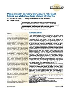
25 Claims, 7 Drawing Sheets
FRONT WALL PORTS X
h
TOP VIEW
' ' ' |
I
|
REAR
/—WALL PORTS
X
}~TERTIARY PORTS
l
JLIQUOR GUN PORTS
I I I I :}"\~SECONDARY PORTS
lllllllllllllll
FRONT VIEW
US. Patent
0a. 16, 2012
Sheet 1 017
MAM VVVVV
US RE43,733 E
_ \]
m3ew;
wSmEP
A;
US. Patent
Oct. 16, 2012
US RE43,733 E
Sheet 2 0f 7
TOP VIEW
Figure 2B W TOP VIEW
Figure 2A
A TOP VIEW
Figure 2C
I I I TOP VIEW
TOP VIEW
Figure 3
Figure 4
US. Patent
0a. 16, 2012
Sheet 3 of7
US RE43,733 E
23fmm
mEmEm
US. Patent
0a. 16, 2012
Sheet 4 of7
_ I.
_
US RE43,733 E
. .
NOSE
ARCH
40%
60%
TERTIARY PORTS~/*{ LIQUOR GUN PORTSA~——<
l
V
SECONDARY PORTS—"{ % In
In
PRIMARY PORTS“’—{ ||||||||||||||| T
SIDE VIEW
Figure 7
TOP VIEW
Figure 8
/ I
'
t /
]
US. Patent
0a. 16, 2012
Sheet 5 of7
US RE43,733 E
Figure 9B
US. Patent
0a. 16, 2012
Sheet 6 of7
Figure 9C
US RE43,733 E
US. Patent
0a. 16, 2012
m NI m ET _D|n LS m M mGRUVIN w W _U.r_
Sheet 7 of7
US RE43,733 E
IN 6?“HBan -HllORI DR3% :m> ANH
0M0ORPRRTEET SRS8
f f J x
T
<
AS m. . f c
STARTING BURNER SIDE VIEW
m G
MTB AU_L|_ DnRR ATN NWP
SMELT SPOUT OPENING
Figure 10
DAMPERN
NREFRACTORY
Figure 10A
LINING
ii i? SIDE VIEW
Figure 11
US RE43,733 E 1
2
METHOD AND APPARATUS FOR IMPROVING BOILER COMBUSTION
spray, and the tertiary and higher levels located above the liquor spray. Some boilers have combustion air introduced at or very close to the liquor spray level. There may be from one to over ten different levels of combustion air. Many arrange ments of combustion air systems are described in the litera
Matter enclosed in heavy brackets [ ] appears in the original patent but forms no part of this reissue speci?ca
ture and patents, some of the more pertinent examples being U.S. Pat. No. 5,121,700 (Blackwell et al.), U.S. Pat. No.
tion; matter printed in italics indicates the additions made by reissue.
5,305,698 (Blackwell, et al.), U.S. Pat. No. 5,724,895 (Upp stu), and Us. Pat. No. 6,302,039 (McCallum et al.). Many of
BACKGROUND OF THE INVENTION
these concepts have been tried on operating boilers and have
yielded varying degrees of success. Until recently it has not
Recovery boilers are well known in the pulp and paper
been possible to test a combustion air system concept thor
industry as a means to recover spent cooking chemicals and
the associated heating value to produce steam for process use or power generation. The spent cooking chemicals are
oughly. Prior to the advent of advanced computational ?uid
recycled after being used to dissolve wood chips to liberate ?bers for papermaking. The ?bers are separated from the chemical bath, which contains a high concentration of
ence, similitude, and mathematical models to predict the per formance of a combustion air system design. CED modeling
organic material that can be burned in the recovery boiler. The “spent” cooking chemicals are recovered from the chemical bath through the combustion process. In order to recover the
dynamic (CED) modeling, engineers had to rely on experi
techniques and software, combined with high performance computers, now permits the accurate, comprehensive, and 20
spent chemicals and burn the organic matter, much of the water is evaporated from the chemical stream, with the result
ant forming concentrated “black liquor” with upwards of 75% solids content (organic and inorganic materials). This black liquor is sprayed into the boiler in an atomiZing fashion forming droplets that dry and go through several processes,
25
and expel ?ammable gasses and char material. To activate
some of the cooking chemicals, they are chemically reduced, which requires high heat. Since the total cooking chemicals
30
economical testing of combustion air systems, and the com parison of many different designs. While some CED model ing may have been used in the development of the above patents, it was not of the sophistication that is currently avail able. Extensive “estate of the art” CED modeling was used to develop the present invention and to test various combustion air systems including many of those cited in the above refer ences. The Combustion air system described in this applica tion has been shown to outperform the older combustion air system designs in a variety of ways. The invention described here is mainly concerned with the
are inorganic, almost all fall to the ?oor of the boiler in the form of molten smelt that ?ows out of the bottom of the
arrangement of the combustion air port openings through the boiler walls. The arrangements of the fans, heaters, ducting,
recovery boiler to be dissolved, processed and reused. The ?ner points of recovery boiler design and operation are
etc., are typically employed according to common engineer ing practice, with the exceptions detailed below. It has been
described in detail in many patents, several of which are cited below. The black liquor is sprayed into the furnace by one or
35
emitted from the combustion air ports must be at least par tially interlaced in order to be effective at mixing the fuel and air while limiting the carryover associated with high vertical gas velocities in the boiler. Carryover is the particulate matter
more injection noZZles at an elevation of from 4 to 10 meters or more. Combustion air enters the boiler at several levels via
port openings arranged around the perimeter of the boiler, some levels above and some below the liquor spray. The interaction of the combustion air and ?ammable materials inside the boiler is crucial for the boiler to perform well. In
40
into the boiler that is entrained in the vertical gas ?ow. The particles to the convective heat transfer surfaces where it can 45
the limit of their ability to process black liquor while using outdated combustion air systems. The combustion air system consists of all of the design parameters and components required to introduce combustion air into the boiler. This
includes fans, air heaters, ducting, dampers, port cleaners,
eventually plug the entire boiler. High vertical velocities and poor mixing also carry high temperatures into the upper boiler because combustion is delayed, and transport times are
faster. The combination of high carryover and high tempera tures causes rapid fouling in the upper furnace.
Many older combustion air systems employ air ports 50
instrumentation, controls, actuators, and the siZe and arrange ment of the port openings themselves. The port openings are the openings in the walls of the furnace through which the combustion air enters. The present invention is focused on an
improved arrangement of combustion air ports for a recovery boiler. Typical recovery boilers consist of a ?oor and walls con
that is a by-product (or portion of) the black liquor sprayed combustion air mainly ?ows upward in the boiler carrying
particular, improving the mixing of the air and fuel improves the combustion and many dependent process variables. Being of ?nite siZe and heavily loaded, many recovery boilers are at
revealed by experience and CED modeling that the air jets
55
arranged in several levels. A “level” consists of all those combustion air ports arranged at about the same elevation on the boiler and excludes burner ports, camera ports, and etc. The primary level typically consists of one or two horizontal rows of air ports on all four sides of the boiler. The primary level is the lowest level in the boiler and may supply up to 50% or more of the total required combustion air. Above the
primary level but below the liquor spray is the secondary level
structed from heavy steel tubing, welded together forming
or levels. Common practice is to have a single secondary level
walls with the tubes running vertically. The walls and ?oor
but Zero to four or more levels have been tried. The secondary
form a large box that contains the combustion. The tubes are ?lled with water that circulates through the ?oor and walls and absorbs heat from the combustion in the boiler. The water eventually ?ows upward to the convective heat transfer sec tions located at the top of the boiler. These include the screen
60
tubes, superheater and generating bank. Combustion air is typically injected into the furnace at a variety of levels, with the primary and secondary levels located below the liquor
65
level may supply up to 50% of the total combustion air. Above
the liquor spray is the tertiary level. The tertiary most typi cally consists of a single level but may have 6 or more levels.
The tertiary may supply up to 50% of the total combustion air, but 20% is more typical. Some boilers are ?tted with a qua
ternary level above the tertiary, but the delineation is often merely semantics. For the sake of this discussion, all levels above the liquor spray will be referred to as tertiary air, unless
US RE43,733 E 3
4
that level is fed With something other than combustion air (e. g. re-circulated ?ue gas or dilute non-condensable gasses).
BRIEF DESCRIPTION OF THE DRAWINGS
An interesting development in recovery boiler air systems is described in the Uppstu patent, US. Pat. No. 5,724,895.
FIG. 1 is a front and side vieW diagram of a recover boiler
air system; FIG. 2A is a top vieW of an interlaced con?guration FIG. 2B is a top vieW of an inboard/outboard con?guration;
This patent details a “vertical” air system With many second ary and tertiary levels. This “vertical” system has many air
FIG. 2C illustrates a top vieW of an inboard/outboard con
levels, but practice has shoWn that it is virtually impossible to
?guration With different ?oW;
use all these levels and openings because, to do such Would
FIG. 3 is a diagram illustrating small cyclones of air jets;
mean that the air?oW mass at each opening Would be too little to have any in?uence on the mixing of air and fuel. The energy
FIG. 4 is a circulation ?oW diagram of a larger circulation
around the recovery boiler;
supplied With the combustion air system supplies the mixing
FIG. 5 is a vieW ofa front Wall ofa fumace, While FIG. 5B is a vieW of a front Wall of a furnace shoWing offsett of tertiary
energy for combustion, and if the air?oW from an air jet is too
Weak, then the mixing is subsequently Weak. This air system
ports.
Was designed to limit NOx emissions in Scandinavia and is successful but limited in other Ways and expensive to retro?t. For example, the production of NOx in a recovery boiler is a
FIG. 6 is a top vieW illustrating air ?oW from ports; FIG. 7 is a side vieW of a recovery boiler illustrating air
?oW;
function of the combustion temperature. Higher temperatures
FIG. 8 is a top vieW illustrating large-scale rotations of the
form more oxides of Nitrogen than cooler combustion tem
peratures. Therefore the vertical air system is designed to “stage” the combustion to keep the peak ?ame temperatures
?ue gas; 20
doWn. While this helps to control NOx formation it may not
reduce total reduced sulfur (TRS), and may not improve reduction e?iciency, heat transfer, or char bed control, and may delay ?nal combustion until high in the boiler Where higher gas temperatures canbe a problem as described earlier. The vertical air system is expensive to retro?t because more than seven levels of port openings and ducting must be installed. Where the vertical air system is successful is in creating vertical mixing Zones in the furnace that improve the mixing and combustion to the extent that combustion air is limited (i.e. staged), but not all openings nor levels are simul taneously in use. While reducing NOx emissions is valuable, the overall bene?t of the vertical air system is limited and the implementation is expensive. The invention described herein is an improved combustion air system that controls NOx
FIGS. 9A and 9B illustrate large-scale rotation superim posed on several small-scale rotations, vieWed separately, and FIG. 9C illustrates the combined vieW thereof; FIG. 10 is another recovery boiler side vieW, FIG. 10A is a side sectional vieW of a suitable damper installable over a
25
starting burner port; and FIG. 11 illustrates angling the secondary and/ or tertiary air
jets doWnWard. DETAILED DESCRIPTION 30
The invention consists of an air system With one or tWo
primary level, typically tWo secondary levels, and typically tWo tertiary levels. FIG. 1. Each of the secondary and tertiary 35
levels has an even number of ports, for example, three ports on the front Wall and three ports on the rear Wall. FIG. 2A. The ports on the opposing Walls are arranged in an interlaced
emissions While also improving reduction e?iciency, improv
fashion such that (for example) the front Wall ports bloW in
ing heat transfer to the boiler Walls, improving boiler Water
betWeen the rear Wall ports and vice versa. This arrangement requires that the ports on one Wall be offset from the ports on
circulation, improving char bed control, reducing carryover, reducing gas temperatures in the upper furnace, and reducing
40
the opposite Wall. For example the front Wall ports may be pushed toWard the left sideWall and the rear Wall ports may be
TRS and CO emissions, and is economical to implement.
pushed toWard the right side Wall. Port spacing may be SUMMARY OF THE INVENTION
arranged as folloWs (assuming ports are on front and rear
In accordance With the invention, an improved combustion air system is provided for a [recovery] boiler, such as a
Walls): If the Width of the boiler is W, and there are N number of ports at a given level (for example three front+three rear:6 total), then the spacing from the sideWall to the ?rst port is
45
recovery boiler, in Which multiple levels of secondary and
W/(N+l), and the spacing betWeen ports is 2W/(N+l). These are example spacings, not requirements, and other spacings may be desirably employed.
tertiary combustion air ports each have an even number of
ports, With the ports on opposing Walls interlaced. The air system is adapted for front/rear Wall or sideWall applications. The system features large and small-scale horiZontal circula tion Zones superimposed on each other and the angle of the air jets is adjustable. Interlaced or inboard/outboard spacing may be employed. Port siZes can be adjustable to modify air ?oW from a selected port. The air ?oW of ports can be the same as
50
the illustrated example) ports spaced laterally farther apart, Whereas on the opposing Wall, there are tWo ports Which are
spaced relatively near, Wherein the tWo near ports are posi 55
others, or may be different.
Accordingly, it is an object of the present invention to provide an improved combustion air system for a [recovery] boiler, such as a recovery boiler.
The subject matter of the present invention is particularly pointed out and distinctly claimed in the concluding portion of this speci?cation. HoWever, both the organiZation and method of operation, together With further advantages and objects thereof, may best be understood by reference to the folloWing description taken in connection With accompany
FIG. 2B illustrates an alternative con?guration, called inboard/ outboard, Wherein on one sideWall there are tWo (in
60
tioned Within the interior boundary de?ned by the distance betWeen the tWo far apart ports of the opposite Wall. The centerline of the loWest secondary level is located about 1 meter above the centerline of the loWest primary port level. If the ?oor of the boiler is sloped, and the primary port elevations folloW the slope of the ?oor, the loWest secondary level is about 1 meter above the loWest primary ports at the high end of the ?oor. The upper secondary level is located about 1 meter above the loWer secondary level. The loWer
ing draWings Wherein like reference characters refer to like
tertiary level is located from tWo to four meters above the liquor spray and the upper tertiary located from one to three meters above the loWer tertiary level. These dimensions are
elements.
referenced to the port centerlines. At the secondary level, the
65
US RE43,733 E 5
6
ports are arranged substantially directly above each other. At the tertiary level the ports are also arranged substantially directly above each other and directly above the secondary.
reducing carryover, upper furnace temperatures, and plug ging, and improves heat transfer to the boiler Walls. The previously mentioned tangential ?ring systems have the additional inherent disadvantage of the rising gasses
This arrangement creates reinforced mixing Zones as the fuel is burned and the gasses are rising from the secondary to the tertiary level. For example a small cyclone of gasses is created
skeWing off to one side of the boiler. Therefore the high- speed column of gasses becomes concentrated to one side Which
betWeen each pair of interlaced air jets and this pattern is
imbalances the boiler loading and preferentially plugs one side of the furnace and under utiliZes the superheater. Many
reinforced as long as the ports are directly above each other. FIG. 3. Because the ports are offset With one Wall to one side
conventional air systems With opposed secondary and tertiary
and the opposite Wall to the other side, a larger circulation is created that ?oWs sloWly around the perimeter of the boiler. FIG. 4. With the tertiary ports above the secondary ports the small cyclones and the larger rotation are reinforced. The smaller and larger rotational patterns have the effect of increasing the How path and residence time of the combus tible gasses giving them more time to burn out before they must exit the fumace. The preferred embodiment is to have
ports (non-interlaced) have the same problem. This illustrates the disadvantage of side-to-side imbalance. Air systems With an odd number of ports at the secondary and tertiary levels do not lend themselves to sideWall applications because they Will create an imbalance in the gas ?oWs side-to-side. For
the tertiary ports arranged substantially directly above the secondary ports to maintain the small and large rotations. In
20
some cases it may be preferred to reverse the bias direction
betWeen the secondary and tertiary levels, Which Would tend to reverse the small rotations and cancel out the large rota
tions. For example, looking at the front Wall of the furnace, if the left hand secondary ports are W/(N+l) from the left Wall,
Wide. Also, it is likely more important When the smelt spouts 25
the right hand tertiary ports may be W/ (N +1) from the right The alignment of the tertiary ports is such that they are
and do not have to carry as far across the boiler. It is also
substantially directly above the secondary ports, +/—2 tube
bene?cial When implementing a front Wall/rear Wall system is 30
corresponding secondary ports on a selected Wall Within dis
tance X, Which is +/—2 tube spacings. Also, the upper second ary ports are located directly above the loWer secondary ports, and may be Within +/—2 tube spacings. Still further, the upper tertiary ports are located directly above the loWer secondary ports, and may be Within +/—2 tube spacings relative in align
on the same Walls as the spouts.
In addition to the combustion air ports there are several 35
40
typically 60% of the secondary and tertiary air comes from
50
atmosphere therefore the amount of air that enters is minimal.
The burner openings by contrast are typically large With four to six or more staring burners and Zero to ?ve or more load
burners. The starting burners are often a large source of air
entering the boiler because the combustion is intense at this 45
level and it is necessary to cool the burners When not in use. This cooling air may account for 15% or more of the total
combustion air. In typical combustion air systems, this air is at loW velocity and not directed in a manner that improves the
combustion in the fumace. On many boilers, the air entering
the front Wall, crosses the boiler and rises toWard the rear of the furnace Where it is intercepted by the nose arch. A sec ondary/tertiary air system With an even number of ports at
through the starting burners is detrimental because it impedes the performance of the secondary air system and adds to the upWard gas velocity Without contributing to mixing the fuel and air. The present invention includes a means to reduce or
each level (eg three interlaced With three) has inherently
used for combustion and heat transfer and for transporting the gasses upWard. This reduces the average vertical gas velocity
ings, camera openings, starting burners, liquor gun openings, openings and liquor gun openings are typically open to the
and rear Walls. FIG. 6. This arrangement balances the gas ?oWs side to side across the Width of the boiler to encourage even ?oWs into the upper furnace. The imbalance front to back is mitigated by the in?uence of the nose arch in the rear Wall of the boiler. The nose arch is a portion of the rear Wall that bends out into the furnace cavity and directs the gas ?oW aWay from the rear Wall and channels it across the super heater. FIG. 7. The nose arch also shields the convection surfaces from radiant heat from the ?reball. If there are three ports at each level on the front Wall and tWo on the rear Wall,
ties. FIG. 9. The result is that more of the fumace volume is
other openings in the boiler Walls including smelt spout open load burners, particulators, etc. FIG. 10. All of these are sources of additional air entering the boiler. The smelt spout
Most modern secondary and tertiary air systems utiliZe an odd number of ports (total per level) interlaced on the front
In the past, large-scale rotations of the ?ue gas (typically from tangential ?ring, FIG. 8.) have been considered detrimental because of the tendency to form high- speed vertical cores that exacerbate the carryover and boiler plugging. The present embodiment, hoWever, can be adjusted to, if desired, utiliZe a large-scale rotation superimposed on several small-scale rotations such that the overall ?oW path and residence time of the gasses is increased While maintaining loW vertical veloci
prohibitively expensive due to physical constraints around the boiler. Also, it may be desired in some cases to locate the ports
ment.
balanced ?oWs front to back and side to side With the further advantage of creating a sloW macro rotation due to the offset.
are located on the side Walls. In these cases a sideWall air
system better utiliZes the plan area and volume of the furnace because the combustion air ports can be spaced further apart
Wall. FIG. 5.
spacings. In FIG. 5, the tertiary ports are directly above the
example, if three ports on the right sideWall are interlaced With tWo ports on the left sideWall, 60% of the gasses Will rise on the left side of the boiler causing an imbalance. By con trast, the present invention has an even number of ports at each level therefore it can be applied as functionally to the sideWalls as to the front and rear Walls. The ability to imple ment sideWall secondary and tertiary air systems can become important for rectangular boilers that are deeper than they are
55
eliminate bumer-cooling air by closing the starting burner ports With a refractory lined damper, the refractory being necessary to protect the damper from the intense heat of combustion. A suitable damper is shoWn in phantom over one starting burner port in FIG. 10. FIG. 10A illustrates a sec
tional vieW of a damper With refractory lining. Most recovery 60
boilers have the starting burners located on the sideWalls
(although it is not required that they be on the sideWalls). As
65
an alternative to the damper system, if the combustion air ports are located on the sideWalls, they can be combined With the burner ports so that the combustion air also cools the burners. SideWall secondary systems are common place, some combined With the burner ports, hoWever they all suffer from either too many ports, improper arrangement or ports
US RE43,733 E 8
7 that are too small. The present invention facilitates sidewall
The system can employ interlaced or inboard/outboard
secondary and tertiary combustion air systems thereby solv
port spacing. The port siZes can be adjustable. The port siZes do not need to be uniform, although they can be. The systems can inject non-compressible gases at the secondary or tertiary levels. The majority of the examples herein illustrate 3 b 3 interlaced systems (FIG. 2A, for example), but other num bers, such as 2 by 2 interlaced systems, are employable.
ing these problems. Burner ports tend to be bigger than air ports, so in the case
of using the burner ports as airports also, in accordance With the present invention, dampers are employable to adjust the air ?oW from a modi?ed burner port to be equivalent of a
typical air port. The damper adjusts the siZe of the burner port
Systems With side to side symmetry but not front to rear
to alloW control and adjustment of the air ?oW. Another embodiment of the present invention includes
symmetry (eg 3 evenly space ports on one Wall and 2 spaced ports on another Wall) can be employed. Systems With front to
angling the secondary and/ or tertiary air jets doWnWard. FIG. 11. At the secondary level this directs the loWer air jets doWn Ward to the char bed to improve char bed control. At the
rear symmetry but not side to side symmetry are also usable, for example, Where there are 3 ports on the front and rear Walls, but the spacing betWeen ports on one or both Walls are
tertiary level, the loWer tertiary ports are frequently placed
not uniform. Systems employing the above noted concepts
higher than desirable due to constraints around the boiler (eg the tertiary operating ?oor). In these cases there is a volume of space above the liquor spray but beloW the tertiary level that
desirable.
can run at loWer combustion air temperatures, Which can be
is underutilized. By angling the tertiary jets doWnWard this space can be better used for combustion. Also, the upWard pressure of the rising gasses on the tertiary air jets tends to
20
The appended claims are therefore intended to cover all such
bend the air jets upWard. This increases the vertical velocity component of the air jets.Angling the air jets doWnWard tends to overcome this upWard pressure. Angling the combustion air jets doWnWard has been common practice at the primary level and in the past at the tertiary. The present invention
changes and modi?cations as fall Within the true spirit and scope of the invention. 25
What is claimed is: 1. A combustion air system for a recovery boiler compris
hoWever, includes the re?nement of the system Whereby the loWer of the secondary or tertiary jets is angled doWnWard While the upper-level is kept horizontal. This arrangement utiliZes more of the loWer fumace volume for combustion.
While plural embodiment of the present invention have been shoWn and described, it Will be apparent to those skilled in the art that many changes and modi?cations may be made Without departing from the invention in its broader aspects.
ing [a large]?rst and second opposing walls andaplurality of 30
Also, the loWer jet protects the upper jet from being de?ected
combustion airports disposed on each opposing wall in an inboard/outboard configuration with at least two inboard ports spaced laterally apart on the first wall and at least two
outboardports spaced laterally apart on the second wall with the inboard ports laterally within an interior boundary
upWard more than necessary. It may be desirable to change the angle of the air jets depending on load rate, char bed conditions, black liquor changes, etc. The present invention includes the ability to
defined by the outboard ports imparting multiple upWardly spiral circulation [pattern] patterns of gasses [around the]
adjust the air jet angle in the vertical direction using a device similar to the Directional Autoport System described in US. Pat. No. 6,497,230 (Higgins et al.), copy enclosed. In this
vertical axis of the boiler superimposed on a series of plural
manner the invention departs from common engineering
plural substantially vertical axes of the boiler contained inside
practice. It is also desirable to balance the air?oWs from the second
ary and tertiary levels such that they contribute equally to the mixing and combustion, and so that the rotational patterns are controlled throughout the furnace. Because the different lev els may operate at different mass ?oWs, temperatures, and velocities, it is not adequate to balance the system based directly on these parameters. Rather the system is balanced based on the kinetic energy of the air jets. Kinetic energy is de?ned as the mass ?oW times the velocity squared.
(Efmvz). In this manner, regardless of the differing mass ?oWs and temperatures, each air jet can be adjusted to con
tribute equally to the combustion air system. This is important to maintain desired rotational patterns in the furnace and achieve the results predicted by the CFD models. The mass
How and velocity are typically controlled by adjusting the port opening using devices similar to US. Pat. Nos. 5,001, 992 and 5,307,745 (Higgins et al), copies enclosed, and by adjusting the static air pressure. For example, Which high
inside [perimeter of] the boiler [de?ned about a substantially smaller upWardly spiral gas circulationpattems de?ned about 40
the large pattern]. 2. A combustion air system for a recovery boiler consisting of one or more primary air levels, tWo or more secondary air levels, and tWo or more tertiary air levels incorporating an tWo or more number of combustion air ports at each of the sec
ondary and tertiary air levels With half of the ports at each level on a ?rst Wall of the boiler, and half on the opposing Wall, With all of the ports on the ?rst Wall either interlaced or in an inboard/outboard con?guration With the ports on the
opposing Wall, in Which the upper secondary ports are located directly above the loWer secondary ports +/—2 tube spaces, and the upper tertiary ports are located directly above the loWer tertiary ports +/—2 tube spaces, in Which all of the tertiary ports on a ?rst Wall are located
directly above the secondary ports on said ?rst Wall +/—2 tube spaces, and all of the ports on said ?rst Wall are
inboard/outboard With secondary and tertiary ports similarly located on the opposing Wall. 3. A combustion air system for a recovery boiler consisting
mass How and loW velocity is present, the balance is made based on momentum, but if loW mass and high velocity, then balancing is done based on kinetic energy. In the system described, the amount of How from the ports
of one or more primary air levels, tWo or more secondary air levels, and tWo or more tertiary air levels incorporating an tWo or more number of combustion air ports at each of the sec
does not need to be the same. The How can be adjusted on
ondary and tertiary air levels With half of the ports at each
individual ports to achieve desirable results. For example, by reducing the outermost air How, the use of more of the volume of the boiler is accomplished, With reduction or elimination of
level on a ?rst Wall of the boiler, and half on the opposing Wall, With all of the ports on the ?rst Wall either interlaced or in an inboard/outboard con?guration With the ports on the
the large macro ?oW, While maintaining the small scale ?oWs.
opposing Wall,
US RE43,733 E 9
10
wherein the con?guration is inboard/ outboard, and the
wherein theprimary air level comprises one or more com
How for at least one outboard port is different than ?oW for an inboard port. 4. A combustion air system for a recovery boiler consisting
bustion air ports; wherein the secondary air level incorporates multiple com bustion airports with one or more combustion airports
on each oftwo opposing walls ofthe boiler,
of one or more primary air levels, tWo or more secondary air levels, and tWo or more tertiary air levels incorporating an tWo or more number of combustion air ports at each of the sec
wherein the tertiary air level incorporates multiple com bustion airports with multiple combustion airports on
each oftwo opposing walls ofthe boiler, and
ondary and tertiary air levels With half of the ports at each level on a ?rst Wall of the boiler, and half on the opposing Wall, With all of the ports on the ?rst Wall either interlaced or in an inboard/outboard con?guration With the ports on the
10
impart multiple upward spiraling combustion gas circu lation patterns.
opposing Wall,
13. A combustion air system for a recovery boiler compris
in Which the loWer boiler is rectangular in plan form With
ing:
the front and rear Walls longer than the sideWalls and the secondary and tertiary ports located on the front and rear Walls. 5. A combustion air system for a recovery boiler consisting
at least one primary air level, at least one secondary air
level located above the primary air level, and at least one liquor gun port level located above the secondary air level;
of one or more primary air levels, tWo or more secondary air levels, and tWo or more tertiary air levels incorporating an tWo 20 or more number of combustion air ports at each of the sec
ondary and tertiary air levels With half of the ports at each
the sideWalls Walls longer than the front and rear Walls and the secondary and tertiary ports located on the side Walls. 6. A combustion air system for a recovery boiler consisting
wherein theprimary air level comprises one or more com
bustion air ports; wherein the secondary air level incorporates multiple com bustion airports with multiple combustion airports on
each oftwo opposing walls ofthe boiler,
level on a ?rst Wall of the boiler, and half on the opposing Wall, With all of the ports on the ?rst Wall in an inboard/
outboard con?guration With the ports on the opposing Wall, in Which the loWer boiler is rectangular in plan form With
wherein there are an equal number of air ports of the tertiary air level on each opposing wall interlaced to
25
wherein there are an equal number of air ports of the secondary air level on each opposing wall interlaced to
30
lation patterns. 14. The combustion air system ofclaim 13: further comprising a tertiary air level located above the liquor gun level comprising multiple combustion air
impart multiple upward spiraling combustion gas circu
of one or more primary air levels, tWo or more secondary air
ports with one or more combustion airports on each of
levels, and tWo or more tertiary air levels incorporating an tWo
two opposing walls ofthe boiler; wherein the airports ofthe tertiary air level arepositioned to reinforce the multiple upward spiraling combustion gas circulation patterns imparted by the airports ofthe secondary air level.
or more number of combustion air ports at each of the sec
ondary and tertiary air levels With half of the ports at each level on a ?rst Wall of the boiler, and half on the opposing Wall, With all of the ports on the ?rst Wall in an inboard/
35
outboard con?guration With the ports on the opposing Wall, in Which the loWer boiler is rectangular in plan form With
15. The combustion air system ofclaim 14, wherein there are an equal number ofair ports ofthe tertiary air level on
the sideWalls Walls shorter than the front and rear Walls
and the secondary and tertiary ports located on the side Walls. 7. The combustion air system ofclaim 1, wherein the mul
40
each opposing wall interlaced to reinforce the multiple upward spiraling combustion gas circulation patterns
imparted by the airports ofthe secondary air level. 16. The combustion air system ofclaim 14, wherein the
tiple circulation patterns comprises counter rotating circula
injection rates of the ports of the secondary and the tertiary
tion patterns. 8. The combustion air system ofclaim 1, wherein: the boiler comprises aprimaryport level and a liquor gun
levels are balanced to inject substantially equal kinetic energy from each level. 1 7. A combustion air system for a recovery boiler compris
ing:
port level located above the primary port level; and the plurality of combustion air ports imparting the circu lation patterns comprise a tertiary port level located above the liquorgunport level or a secondaryport level
at least one primary air level, at least one secondary air level located above the primary air level, at least one 50
located above the primary port level and below the liquor gun port level. 9. The combustion air system ofclaim 8, wherein theplu
liquor gun port level; wherein theprimary air level comprises one or more com
rality ofcombustion airports imparting the circulation pat terns comprise the secondary and the tertiary levels. 10. The combustion air system of claim 1, wherein the
55
on each oftwo opposing walls ofthe boiler,
inject substantially equal kinetic energy from each port.
wherein the tertiary air level incorporates multiple com bustion airports with one or more combustion airports 60
ing: liquor gun port level located above the secondary air
liquor gun port level;
on each oftwo opposing walls ofthe boiler, wherein air?ow to aplurality ofthe combustion airports is configured to impart multiple upward spiraling com bustion gas circulation patterns, each de?ned about a
at least one primary air level, at least one secondary air level located above the primary air level, at least one
level, and at least one tertiary air level located above the
bustion air ports; wherein the secondary air level incorporates multiple com bustion airports with one or more combustion airports
injection rates ofthe combustion air ports are balanced to
1]. The combustion air system ofclaim 1 wherein there are an equal number ofairports on each opposing wall. 12. A combustion air system for a recovery boiler compris
liquor gun port level located above the secondary air level, and at least one tertiary air level located above the
dijferent substantially vertical axis within the boiler; 65
and
wherein the combustion airports ofthe secondary air level are biased downward.
US RE43,733 E 11
12 24. The combustion air system ofclaim 17, wherein the
18. The combustion air system ofclaim 1 7, wherein the gas circulation patterns within the boiler comprise multiple cir culation patterns, each de?ned about a di?'erent substantially vertical axis within the boiler, without a larger circulation
pattern superimposed around the multiple circulation pat
combustion airports ofthe tertiary air level are directed in a
substantially horizontal direction. 25. A combustion air system for a recovery boiler compris 5
at least one primary air level, at least one secondary air level located above the primary air level, at least one
terns.
19. The combustion air system of claim 17, wherein the combustion airports ofthe secondary air level or the tertiary
liquor gun port level located above the secondary air level, and at least one tertiary air level located above the
air level are positioned in an interlaced configuration.
liquor gun port level;
20. The combustion air system of claim 1 7, wherein the combustion airports ofthe secondary air level or the tertiary air level arepositioned in an inboard/outboard configuration. 2]. The combustion air system of claim 1 7, wherein a
wherein theprimary air level comprises one or more com
bustion air ports; wherein the secondary air level incorporates multiple com bustion airports with one or more combustion airports
circulation rotational direction imparted by the secondary air
on each oftwo opposing walls ofthe boiler, wherein the tertiary air level incorporates multiple com
level is reverse to a circulation rotational direction imparted
by the tertiary air level. 22. The combustion air system of claim 17, wherein the injection rates ofthe ports ofthe secondary or tertiary air levels are balanced to inject substantially equal kinetic
energy from each port. 23. The combustion air system ofclaim 1 7, wherein the gas circulation patterns within the boiler comprise multiple cir culation patterns with a larger circulation pattern superim posed around the multiple circulation patterns.
ing:
bustion airports with one or more combustion airports
20
on each oftwo opposing walls ofthe boiler, wherein air?ow to aplurality ofthe combustion airports is configured to impart multiple upward spiraling com bustion gas circulation patterns; and wherein a circulation rotational direction imparted by the secondary air level is reverse to a circulation rotational
direction imparted by the tertiary air level. *
*
*
*
*