Copyright WILEY‐VCH Verlag GmbH & Co. KGaA, 69469 Weinheim, Germany, 2015.
Supporting Information
for Adv. Mater., DOI: 10.1002/adma.201503033
Realization of Room-Temperature Phonon-Limited Carrier Transport in Monolayer MoS2 by Dielectric and Carrier Screening Zhihao Yu, Zhun-Yong Ong, Yiming Pan, Yang Cui, Run Xin, Yi Shi,* Baigeng Wang, Yun Wu, Tangsheng Chen, Yong-Wei Zhang, Gang Zhang,* and Xinran Wang*
Copyright WILEY-VCH Verlag GmbH & Co. KGaA, 69469 Weinheim, Germany, 2013.
Supporting Information Realization of Room-Temperature Phonon-limited Carrier Transport in Monolayer MoS2 by Dielectric and Carrier Screening Zhihao Yu, Zhun-Yong Ong, Yiming Pan, Yang Cui, Run Xin, Yi Shi*, Baigeng Wang, Yun Wu, Tangsheng Che4, Yong-Wei Zhang, Gang Zhang* & Xinran Wang*
Supplementary Information 1. Details of theoretical calculations 2. Growth and characterizations of high-κ oxides 3. Sample preparation, device fabrication and electrical measurements 4. Additional electrical data of devices on Al2O3 and HfO2 substrate
1
1.
Details of theoretical calculations To analyze the electron mobility in monolayer MoS2, we use a semiclassical model based
on the relaxation time approximation. The electrons are assumed to move diffusively in the MoS2 sheet, with an effective mass1 of m* = 0.48m0 where m0 is the free electron mass. However, their mobility is limited by scattering processes intrinsic and extrinsic to MoS2. The expression for the electron mobility is given by2, 3
µ=
2e π nℏ 2 k BT
∫
∞
0
f ( E )[1 − f ( E )]Γ( E ) −1 EdE
(S1)
where e , n , ℏ , k B and T are the electron charge quantum, the electron density, the Planck constant divided by 2π, the Boltzmann constant and the temperature, respectively. The functions
f ( E ) and Γ ( E ) in turn represent the Fermi-Dirac distribution and the
momentum relaxation rate. The total electron mobility is computed using Matthiesen’s rule2: −1 −1 µ = ( µCI−1 + µ −ph1 + µ SO ) where µ CI , µ ph and µ SO are the individual mobilities limited by
scattering with CI, intrinsic phonons or SO phonons, respectively, and calculated using Eq. (S1) with the scattering rates Γ CI (Coulomb impurities), Γ ph (intrinsic phonons) or Γ SO (surface optical phonons). The details of how the scattering rates are given in the following discussions.
a. Coulomb impurities Coulomb impurity scattering is due to the charge centers near the oxide surface and also to sulfur vacancies within the MoS2, and is known to be a major source of resistance to electron conduction in 2D crystals. It was shown by Ong and Fischetti3 that CI-limited charge transport can have an electron mobility temperature dependence that is similar to that in phonon-limited charge transport.
2
The screened potential can be expressed as φqscr =
φq ε 2 D ( q, T )
, where φq =
e2 is 0 (ε box + ε 0 )q
0 the bare potential; ε box and ε 0 are in turn the static permittivity of the substrate and vacuum.
The screening of the bare CI by the substrate and the free electrons is described by the generalized screening function ε 2 D (q, T ) = 1 +
2ε el (q ) e2 ε ( q ) = − Π ( q , T , EF ) , where el 0 ε box + ε0 2q
corresponds to the electronic part of the dielectric function. Π ( q , T , E F ) is the temperatureand carrier density-dependent static polarizability, and represents the polarization charge screening of the CI. The exact form of Π ( q , T , E F ) is given in Refs. 3-5. The CI scattering rate is3
ΓCI ( Ek ) =
nCI dk | φ kscr− k ' |2 (1 − cos θ kk ' )δ ( Ek − Ek ' ) , ∫ 2π ℏ
(S2)
b. where θ kk ' is the scattering angle between the k and k ' states and E k is the energy. Thus, the CI-limited mobility µ CI can be calculated using Eqs. (S1) and (S2).Intrinsic phonon
scattering In our model, the intrinsic phonon scattering rate ( Γ ph ) is due to electrons scattering with the longitudinal (LA) and transverse acoustic (TA), the intravalley polar longitudinal optical (Froehlich), the intervalley polar longitudinal optical (LO) and the intravalley homopolar optical (HP) phonons. Thus, we have Γ ph = Γ LA + ΓTA + Γ LO + Γ HP + Γ Fr where Γ LA , Γ TA , Γ LO , Γ HP and Γ Fr are the scattering rates associated with LA, TA, LO, HP and Fr.
phonons. The LA and TA phonon scattering rates are given by Γ ac =
m*Ξ 2ac k BT , where Ξ ac is the ℏ3 ρ cac2
acoustic phonon (LA or TA) deformation potential and cac is the acoustic phonon speed.
3
The intervalley polar longitudinal optical (LO) and intravalley homopolar optical (HP) phonon scattering rates are given by Γ op ( E ) =
m* Dop2 2ℏ 2 ρωop
[ N op + (1 + N op )Θ( E − ℏωop )] , where
D op is the optical deformation potential of the optical phonon (LO or HP) and N op = [exp( ℏωop / kV T ) − 1]−1 is its Bose-Einstein distribution with ωop its phonon energy.
Θ(…) is the usual Heaviside function. In the long wavelength limit, the intravalley polar longitudinal optical (Froehlich) phonons can couple with the electron gas and undergo screening. Thus, the Froehlich optical phonon emission (+) or absorption (-) rate is4:
Γ ±Fr ( E ) =
1 − kk ' cos θ e 2ωFr m* 1 1 1 1 qσ π ± + − 0 N d θ erfc( )2 where Fr ∫ 2 ∞ 8π ℏ 2 2 2 q −π ε ion + ε el (q) ε ion + ε el (q)
k is the initial state, k ' is the final state given by k ' = k 2 ∓ 2m*ωFr / ℏ , and ∞ 0 q = k 2 + k '2 − 2kk 'cosθ . Also, ε ion ( ε ion ) is the ionic part of the optical (static) permittivity
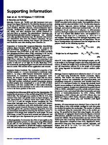
of MoS2, erfc is the complementary error function and σ is the sheet thickness.. We assume the phonon dispersion for the LO phonons to be flat so that ω Fr = ω LO . Therefore, the Froehlich phonon scattering rate is: Γ Fr ( E ) = Γ −Fr ( E ) + Θ( E − ℏωFr )Γ +Fr ( E ) . Fig. S1a shows the intrinsic phonon-limited mobility µ ph as a function of temperature at n=1013 cm-2, calculated using the parameters in Table S1. µ ph decreases with temperature and reaches ∼420 cm2/Vs at 300 K which is the maximum room-temperature electron mobility if there is no scattering with CI and SO phonons and in good agreement with published results1, 4. Fig. S1b shows µ ph as a function of carrier density at 300 K. As we increase n, µ ph grows initially because of the screening of the Froehlich coupling reduces its contribution to the intrinsic phonon scattering rate. However, at higher n, the scattering rate
4
increases because the Fermi level is at the higher energy states where there is greater optical phonon (LO, HP and Fr.) emission and the corresponding scattering rate increases.
Parameter
Numerical value
m*
0.48 m0
Ξ LA ( Ξ TA )
2.8 eV (1.6 eV)
c LA ( cTA )
6700 m/s (4200 m/s)
ρ
3.1×10⁻⁷ g/cm-2
σ
4.41×10⁻¹⁰ m
D LO ( D HP )
2.6×10⁸ eV/cm (4.1×10⁸ eV/cm)
ω LO ( ω HP )
48 meV (50 meV)
0 ∞ ε ion ( ε ion )
7.6 ε 0 (7.0 ε 0 )
Table S1. Parameters used for the intrinsic phonon scattering rates. The values are taken from Ref. 1, 6.
Figure S1. Theory for intrinsic phonon limited mobility. (a) µ ph as a function of temperature at n=1.0×1013cm-2. (b) µ ph as a function of carrier density at T=300K. c. Surface optical phonon scattering
5
Another source of electron scattering is through remote interaction with the polar optical phonons in the dielectric substrate4, 7. We assume that there are two phonon modes in SiO2 and Al2O3. The SO phonon scattering rate is given by Γ SO = Γ SO1 + Γ SO 2 . For HfO2, we assume that there is only one phonon mode though like in Ref. 8. The
dielectric
ε box (ω ) = ε
∞ box
+ (ε
i box
function
of
the
ε box (ω )
substrate
is7,
9
:
2 2 ωTO ωTO 0 i 0 i ∞ 2 −ε ) 2 + (ε box − ε box ) 2 1 2 where ε box , ε box and ε box are 2 ωTO 2 − ω ωTO1 − ω ∞ box
the static, intermediate and optical dielectric of the substrate, respectively,
and ωTO1 and
ωTO 2 are the transverse optical phonon angular frequencies such that ωTO1 < ωTO 2 . We can ε box (ω )
rewrite
ε box (ω ) = ε
∞ box
in
the
generalized
form
2 2 2 2 ωLO ωLO 1 −ω 2 −ω . In the case of HfO2, we consider only one TO mode, 2 2 2 2 ωTO1 − ω ωTO 2 − ω
so that its dielectric function is ε box (ω ) = ε
ε tot∞ , SO =
Lyddane-Sachs-Teller
1 ∞ (ε box + ε 0 ) 2
and
∞ box
+ (ε
0 box
2 2 2 ωTO ∞ ω LO − ω −ε ) 2 = ε box 2 while 2 ωTO − ω 2 ωTO − ω ∞ box
2 ωLO + ε 0 . 2 ωTO
1 2
∞ ε tot0 , SO = ε box
The
surface
optical
phonon
frequencies ( ω SO1 and ω SO 2 ) can be determined from the roots of the equation ε box (ω ) + ε 0 = 0 . The remote interaction with the substrate SO phonons is described by the term
H SO = ∑k ,q M q ck†+q ck (aq + a−†q ) where M q is the coupling coefficient and aq† ( aq ) is the phonon
creation
e2 ℏωSO Mq = Ωq
(annihilation)
operator.
The
coupling
coefficient
is
given
by
12
1 1 − 0 ∞ ε SO + ε el (q) ε SO + ε el (q)
where ω SO is the SO phonon energy (Table
∞ 0 1). ε SO and ε SO are the optical and static dielectric response of the interface, respectively.
The term ε el (q ) represents the screening effect of the electron gas on the surface electric
6
field of the substrate SO phonons and like in CI scattering, depends on the temperature as well as the carrier density. The remote optical phonon emission (+) and absorption (- ) rates (SO1) can be written as
Γ
± SO1
1 − kk' cos θ e2ωSO1m* 1 1 1 1 π θ (E) = ± + N d − SO1 ∫−π 0 ε∞ 8π ℏ2 2 2 q tot , SO1 + ε el (q) ε tot , SO1 + ε el (q)
∞ where ε tot , SO1 =
2 2 2 2 2 ωLO 1 ∞ ωLO 1 ∞ ωLO 0 2 − ωSO1 1 2 − ωSO1 ε ε ε + = and ε box 2 0 2 + ε0 . tot , SO1 box 2 2 2 2 2 ωTO 2 − ωSO1 ωTO1 ωTO 2 − ωSO1
Thus, the SO1 scattering rate is: Γ SO1 ( E ) = Γ −SO1 ( E ) + Θ( E − ℏωSO1 )Γ +SO1 ( E ) . The SO2 scattering rate is similarly defined. Figure S2 shows the SO phonon-limited mobility µ SO calculated using Eq. (S1) as a function of temperature at different values of n for SiO2, Al2O3 and HfO2. We observe that
µ SO increases with n because the remote interaction with the SO phonons undergoes greater screening at higher n like in CI scattering. Also, its decreases with temperature at a greater rate than µ ph . Thus, at room temperature, it is one of the most dominant scattering processes especially for HfO2.
SiO2
Al2O3
HfO2
Al2O3 (ref.) HfO2 (ref.)
ωTO1 (meV)
55.60
48.18
40.0
48.18
40.0
ωTO 2 (meV)
138.10 71.41
-
71.41
-
ω LO1 (meV)
62.57
79.00 56.47
56.47
ω LO 2 (meV) 153.28 120.55 ω SO1 (meV)
60.99
ω SO 2 (meV)
148.87 108.00 -
0 ε box (ε0 )
3.90
56.00
10.00
120.55
73.17 -
16.50 12.53
7
79.0 16.00
i ε box (ε0 )
3.05
5.80
-
7.27
-
∞ ε box (ε0 )
2.50
2.56
4.23
3.20
4.10
Table S2. Parameters used for the SO phonon scattering rates. The values for SiO2 and Al2O3 0 (ref.) are taken from Ref. 3; the values for HfO2 (ref.) are taken from Ref. 8. ε box (or κ) for i Al2O3 and HfO2 are extracted from our capacitance measurements. The other parameters ( ε box ∞ and ε box ) for Al2O3 and HfO2 are obtained by rescaling the values for Al2O3 (ref.) and HfO2
(ref.).
Figure S2. Theory for surface optical phonon limited mobility for different substrates. From top to bottom, n=1.0×1013cm-2(red), 8×1012cm-2 (green), 6×1012cm-2 (cyan), 4×1012cm-2 (blue), 2×1012cm-2 (dark cyan) and 1×1012cm-2 (black).
2.
Growth and characterizations of high-
oxides
We grew 10nm thick high-κ oxide on SiO2/Si substrate by Atomic Layer Deposition (ALD). Before ALD, the substrate was thoroughly cleaned by acetone and isopropanol. For Al2O3, trimethylaluminum (TMA, Micro-nano Tech. Co. Ltd., China) and H2O were used as precursors. For HfO2, tetrakis(dimethylamido)hafnium (TDMAH, Micro-nano Tech. Co. Ltd., China) and H2O were used as precursors. The deposition temperature was maintained at 150 °C for both oxides. We characterized the oxide films by surface roughness and dielectric constant measurements. The average mean-square roughness (Rq) calculated by AFM images is less 8
than 0.2nm (Fig. S3a, b), similar to the SiO2 substrate (Fig. S3c). This confirms the highly uniform and smooth surface of high-κ oxides, which is important for low CI. We measured the dielectric constant of the oxides by standard capacitance measurement with Au/oxide/Au structure using the Agilent E4980A precision LCR meter. The thickness of the oxides is ~100nm as obtained by AFM. We used the capacitance value at 10kHz, due to the negligible change of capacitance in low frequency regime.
Figure S3. AFM characterization of high-κ oxide films. AFM images of (a) Al2O3 on SiO2, (b) HfO2 on SiO2 and (c) bare SiO2. The images all have the same Z scale.
3.
Sample preparation, device fabrication and electrical measurements We used the double-side MPS treatment reported in Ref. 10 for all samples studied here.
Briefly, the 10nm high-κ oxide/285nm SiO2/Si substrate was first subjected to a 30-min UV/ozone treatment to hydroxylate the oxide surface. The substrate was then dipped in a 10% (v/v) MPS/dichloromethane solution for 12 h in a dry glove box to grow MPS self-assembled monolayer. When MPS growth was finished, the substrate was sonicated in dichloromethane followed by thorough rinsing with dichloromethane and IPA, and drying with N2. We then exfoliated monolayer MoS2 from natural flakes (SPI Supplies) on the MPS-treated substrate. After exfoliation, the sample was dipped in a fresh solution of 1/15 (v/v) MPS/dichloromethane for 24 h in a dry glove box to grow MPS on the top side of MoS2,
9
followed by thorough rinsing. Finally, the sample was annealed in a mixture of H2/Ar at 350 ℃ for 20 min to finish the MPS treatment. The source, drain and voltage probe electrodes of the field-effect transistors were then patterned by standard electron beam lithography, followed by electron beam evaporation of Ti/Pd (20nm/20nm) and lift-off. In the ebeam lithography step, we use double layer resist stack (MMA/PMMA), to reduce the exposure dose and form the undercut geometry. The devices were then annealed at 350℃ in Ar atmosphere for half an hour to improve contacts. Transport measurements were performed by a Keithley 4200 semiconductor parameter analyzer in a close-cycle cryogenic probe station with base pressure ~10-5 Torr. 350K in situ vacuum annealing was performed to remove adsorbates and improve device performances before measurement11.
Figure S4. (a) Optical image of monolayer MoS2 devices. (b)AFM image of monolayer MoS2 device with hight of 0.8nm. (c) Raman spectrum of monolayer MoS2 at 514.5 nm excitation. The spectrum is shown with a distance of 19 cm−1 between two vibrating modes (E12g and A1g)12. (d) PL characterizations of monolayer MoS2. .
10
4.
Additional electrical data of devices on Al2O3 and HfO2 substrate
Figure S5. Electrical data and theoretical modeling for device A1 on Al2O3 substrate. (a) Four-probe conductivity as a function of Vg from 300K to 20K. (b) Field-effect mobility as a function of temperature under n=1.0×1013cm-2 (symbols). The solid line is the best theoretical fitting (see Table 1 for fitting parameters). The blue dash line is calculated CI-limited mobility. The black dot line is the calculated phonon-limited mobility. (c) Field-effect mobility as a function of temperature at different carrier densities. The solid lines are the calculated results using parameters in Table 1. From top to bottom, n=1.0×1013cm-2 (red), 8.5×1012cm-2 (green) and 7.0×1012cm-2 (black).
Figure S6. Theoretical (a) and experimental (b) μCI as a function of temperature under n=1.05×1013cm-2. The dash lines show T-γ scaling. Theoretically, the µCI can be fitted by T-γ, where γ is an intrinsic parameter that reflects the dielectric screening. γ decreases as dielectric constant increases, γ=0.46 for HfO2 and γ=0.68 for Al2O3. The experimental data follow the same trend as theoretical predictions. The best power law fitting gives γ=0.4 for HfO2 and γ=0.8 for Al2O3, in reasonable agreement with our simulations.
11
References: 1. 2. 3. 4. 5. 6.
7. 8. 9. 10. 11. 12.
K. Kaasbjerg, K. S. Thygesen and K. W. Jacobsen, Phys. Rev. B 85 (11), 115317 (2012). J. H. Davies, The physics of low-dimensional semiconductors: an introduction. (Cambridge University Press, Cambridge, UK, 1997). Z.-Y. Ong and M. V. Fischetti, Phys. Rev. B 88 (16), 165316 (2013). N. Ma and D. Jena, Phys. Rev. X 4 (1), 011043 (2014). P. F. Maldague, Surface Science 73 (0), 296-302 (1978). S. Kim, A. Konar, W.-S. Hwang, J. H. Lee, J. Lee, J. Yang, C. Jung, H. Kim, J.-B. Yoo, J.-Y. Choi, Y. W. Jin, S. Y. Lee, D. Jena, W. Choi and K. Kim, Nat. Commun. 3, 1011 (2012). Z.-Y. Ong and M. V. Fischetti, Phys. Rev. B 86 (16), 165422 (2012). K. Zou, X. Hong, D. Keefer and J. Zhu, Phys. Rev. Lett. 105 (12), 126601 (2010). M. V. Fischetti, D. A. Neumayer and E. A. Cartier, J. Appl. Phys. 90 (9), 4587-4608 (2001). Z. Yu, Y. Pan, Y. Shen, Z. Wang, Z.-Y. Ong, T. Xu, R. Xin, L. Pan, B. Wang, L. Sun, J. Wang, G. Zhang, Y. W. Zhang, Y. Shi and X. Wang, Nat. Commun. 5 (2014). H. Qiu, L. Pan, Z. Yao, J. Li, Y. Shi and X. Wang, Appl. Phys. Lett. 100, 123104 (2012). C. Lee, H. Yan, L. E. Brus, T. F. Heinz, J. Hone, and S. Ryu. ACS Nano, 4 , 2695, (2010).
12