IEEE TRANSACTIONS ON CIRCUITS AND SYSTEMS FOR VIDEO TECHNOLOGY, VOL. 12, NO. 9, SEPTEMBER 2002
777
Supporting Image and Video Applications in a Multihop Radio Environment Using Path Diversity and Multiple Description Coding Nitin Gogate, Member, IEEE, Doo-Man Chung, Shivendra S. Panwar, Senior Member, IEEE, and Yao Wang, Senior Member, IEEE
Abstract—This paper examines the effectiveness of combining multiple description coding (MDC) and multiple path transport (MPT) for video and image transmission in a multihop mobile radio network. The video and image information is encoded nonhierarchically into multiple descriptions with the following objectives. The received picture quality should be acceptable, even if only one description is received and every additional received description contributes to enhanced picture quality. Typical applications will need a higher bandwidth/higher reliability connection than that provided by a single link in current mobile networks. For supporting these applications, a mobile node may need to set up and use multiple paths to the desired destination, either simply because of the lack of raw bandwidth on a single channel or because of its poor error characteristics, which reduce its effective throughput. In the context of this work, the principal reasons for considering such an architecture are providing high bandwidth and more robust end-to-end connections. We describe a protocol architecture that addresses this need and, with the help of simulations, we demonstrate the feasibility of this system and compare the performance of the MDC–MPT scheme to a system using layered coding and asymmetrical paths for the base and enhancement layers. Index Terms—Error resilience, multiple description coding, path diversity, video transport over wireless networks.
I. INTRODUCTION
T
HIS PAPER considers how to transport image and video signals over mobile multihop radio networks. Most of the coding and transmission schemes proposed for image and video transport over wireless channels employ layered coding with unequal error protection [1]–[4]. With this scheme, a signal is split into a base layer and one or more enhancement layers. The base layer is transmitted with a high priority and with strong error protection, including the use of automatic repeat request (ARQ), while the enhancement layer is transmitted with fewer error control bits and is simply discarded in the case of channel congestion. These methods can tolerate a certain degree of burst errors. However, it will break down if the channel carrying the most important layer fails. Although, following a path failure, Manuscript received February 2000; revised February 2002. This paper was recommended by Associate Editor Osama K. Al-Shaykh. N. Gogate with Fujitsu Network Communications, Pearl River, NY 10965 USA (e-mail:
[email protected]). D.-M. Chung is with the New York City Department of Transportation, Signal Division, Long Island City, NY 11101 USA (e-mail:
[email protected]). S. S. Panwar and Y. Wang are with Polytechnic University, Brooklyn, NY 11201 USA (e-mail:
[email protected];
[email protected]). Publisher Item Identifier 10.1109/TCSVT.2002.803229.
one could switch over to an alternative route, this may take an unacceptably long period of time. In order to enhance the robustness to channel errors and failures, we propose to use multiple description coding (MDC) for compression of image and video signals. With MDC, several descriptions are generated for a given signal, so that a better signal reproduction is achieved with more descriptions, and that the quality of the decoded signal is acceptable even with only one description. MDC was first studied from the rate-distortion point of view [5]–[7]. Many practical coders have been developed since then, including [8]–[13]. A comprehensive review of MDC principle, theoretical bound, and practical multiple description (MD) coders can be found in [14]. In general, an MD coder can directly produce multiple coded streams from a given signal. Here, we propose to first decompose the signal into multiple subsignals and then code each signal independently. The decomposition should be nonhierarchical so that the reconstructed signal from any one description is acceptable under a prescribed criterion. Such a decomposition is very different from the commonly used transform/subband type of decomposition, which is hierarchical in that some subsignals are more important than the others. Although hierarchical decomposition can lead to greater compression gains, it requires that the channel carrying the most important subsignal be essentially error-free. This may be hard to guarantee given the real-time constraint on video signals and the presence of unpredictable path impairments in a radio environment. The motivation for using MDC is to introduce redundancy at the source coder to combat these types of channel errors. Multiple path1 transport (MPT) schemes have been proposed in the past for wired networks for increased connection capacity, as well as for reliability [15]–[19]. The earliest reference to multiple path transport (MPT), referred to as dispersity routing, is from Maxemchuck [15]. End nodes might communicate with each other using multiple parallel paths/routes constituting a single virtual circuit for various reasons. Lee and Liew considered a parallel communications scheme, and the advantages it offers, in the context of ATM traffic control [16]. A channel-coding scheme using multiple parallel paths was considered in [18], which improved the fault tolerance of digital communication networks. One can set up multiple parallel connections either to increase the maximum throughput 1In this paper, we use path and route interchangeably. Hence, in our definition of path/route diversity, two communicating entities make use of more than one paths/routes to send information to each other.
1051-8215/02$17.00 © 2002 IEEE
778
IEEE TRANSACTIONS ON CIRCUITS AND SYSTEMS FOR VIDEO TECHNOLOGY, VOL. 12, NO. 9, SEPTEMBER 2002
between a pair of nodes by spreading the traffic on multiple paths [19] or to circumvent the unavailability of required bandwidth on any one path. A system of two high-speed hosts connected by a wide-area network (WAN) at gigabit speeds, communicating on multiple parallel ATM virtual circuits, with the same available bandwidth on every channel was analyzed in [17]. The incoming packets were distributed in round-robin fashion, and packets in parallel channels could bypass each other because of the varying amount of delay in each channel. We feel that MPT has more potential in wireless networks where individualphysicallinks may not have adequate capacity to support a high bandwidth service. There are several ways to set up multiple paths or links for a single virtual connection in a wireless network. In a single-hop wireless network, a station would need to establish channels to multiple base stations instead of one. This is already done in “soft” hand-off systems, during the hand-off phase. In a multihop wireless network where each station has router-like functionality, each station needs to establish multiple disjoint paths with another wireless station or with the wired network. To achieve this, each mobile must be able to discover multiple routes, and support multiple channels so that it can talk to multiple neighbors simultaneously. For ad hoc networks, many routing protocols have been proposed (e.g., the zone routing protocol [20]). The IETF MANET Working Group has been the main forum for research in this area. Most of the proposed ad hoc routing protocols have the ability to discover multiple routes. In the CDMA system, a node can communicate with multiple neighbors simultaneously by having multiple transceivers in each mobile [21], [22], and using either receiver- or link-oriented codes, or a code for each transmitter–receiver pair. The ability to communicate with multiple neighbors (base-stations), instead of having a higher bandwidth connection to a single base-station, for example by using multiple codes [23], allows for better adaptability to the varying radio channel quality, hand-offs, and alternate routing in the case of a route failure. Analogously, in a FDMA- or a TDMA-based system, a mobile could talk to its neighbors using multiple-frequency channels or time slots. An important issue associated with communications using multiple paths is that of resequencing. As the traffic between a typical pair of end nodes follows different paths, which have different speeds (available bandwidth) and have different number of hops (entailing varying amounts of propagation delay and fixed processing delay), packets belonging to a session may arrive out of order at the destination node. The packets arriving out of order may have to wait in a special buffer called the resequencing buffer, before they can be delivered in the correct order to the destination process. Some additional amount of delay is incurred due to this wait in the resequencing buffer. In [24] and [25], several models have been considered by researchers to evaluate the distribution of resequencing delay and total end-to-end delay. Most of these models considered a source node at the edge of a network, or a network with a single hop. The models considered differ in the number of available channels, the arrival, and the service distributions. In other variations of the resequencing problem, the effect of the fixed-delay associated with each path, along with the queuing and resequencing delay, on the proportion of traffic carried by each path was studied in [26]. In [27] and [51], analytical expressions were
obtained for resequencing delay under a variable routing position threshold policy, which performs better than the previously studied fixed position threshold policy. In the past, MDC and MPT have been studied separately. The splitting of the traffic in MPT is usually done on the bit level in a random manner. Because of the use of prediction and variable-length coding in most image and video coders, the loss of information on one path can render the other received information bits useless. Here, we propose to jointly design MDC and MPT processes to enhance the system robustness while increasing the usable bandwidth for an end-to-end connection beyond that of a physical link. A key to the success of the proposed system is the close interaction between the source coder and the network transport control. By carefully allocating packets from different coded descriptions among the available paths, one can ensure—with high probability—the correct and timely delivery of at least one description for any given spatial location of the source signal, thereby guaranteeing a minimally acceptable quality. By using dynamic path selection and bandwidth allocation on the network control side, scalable (in bit rate and quality) coding of each description on the source coding side, and with close interaction between the two processes, the system can also adapt quickly to changes in link-level connectivity and bandwidth. In this paper, we address the coding and protocol issues associated with transporting video to a desired destination using MDC–MPT. We briefly describe our MD coder and a layered coder, both based on the lapped orthogonal transform (LOT). We present simulation results obtained when the video is coded using the MD coder as well as the layered coder. The two descriptions from the MD coder are transported over two symmetric paths. On the other hand, the base and enhancement layers from the layered coder are delivered over asymmetric paths, simulating unequal error protection. With simple simulation models we show the feasibility of the proposed MDC–MPT architecture from a protocol and resequencing viewpoint and compare the end-to-end performance of an MDC–MPT system with symmetric paths, and that of a layered system with asymmetrical paths. To avoid temporal error propagation, the current video coder processes individual video frames separately. Even though this leads to a significantly higher bit rate than video coders that make use of temporal prediction, the bit stream is more resilient to transmission errors. We believe that the conclusion obtained from this study will be applicable at least qualitatively to future coders that exploit temporal prediction. The paper is organized as follows. In Section II, we describe the system and associated protocol model. In Section III, we describe the scheme for generating multiple correlated descriptions from a single video stream at the sender and the recovery technique at the receiver. The layered coding scheme used in the simulations is also presented. Section IV describes the simulation model in detail. The results are presented and discussed in Section V. Finally, conclusions and future work are outlined in Section VI. II. SYSTEM AND PROTOCOL MODEL A. Overview of the MDC–MPT System The system schematic of the proposed MDC–MPT communications system is shown in Fig. 1. On the sender side, an
GOGATE et al.: SUPPORTING IMAGE AND VIDEO APPLICATIONS IN A MULTIHOP RADIO ENVIRONMENT
779
Fig. 1. System schematic for the proposed MDC–MPT communications system.
MD coder decomposes a source signal into subsignals, each subsignal is then coded, packetized and sent on different paths through a multihop radio network. Each coded subsignal constitutes a description. We assume the rate of each description is and . Each description is divided into slices between so that each slice is carried in a single transport packet. At the receiver, the packets arriving from all the paths are put into a redescripsequencing buffer where they are reassembled into tions after a preset time-out period. All or some of the packets allocated to a path may be lost because of the errors on the path or because of path breakdown. Some packets may arrive late and will also be considered lost. The decoder will attempt to reconstruct the damaged frame from the received packets in separate descriptions. The decomposition and recovery schemes are designed such that any single description can provide minimally acceptable quality signal, and each additionally received description contributes to enhanced image/picture quality. The implementation details of source coding, packetization, and decoder reconstruction are outlined in Section III. B. Transport Control We assume a multihop packet radio network, in which each mobile node is equipped with the ability to transmit and receive on multiple channels. In a conventional cellular network this corresponds to a mobile node capable of communicating with either more than one base station or the same base station using multiple channels. Thus the maximum bandwidth available to the application is the basic channel rate times the number of transceivers. Given that image and video transport can tolerate some amount of loss and may have real time delivery constraints, we consider the real-time transport protocol (RTP) as the transport layer protocol entity [28]. RTP is complemented by a control protocol called RTP control protocol (RTCP), which tackles issues such as quality of service (QoS), mechanisms to disperse QoS and membership information, membership control and identification. RTP provides time-stamping, sequencing and delivery monitoring services to the application. Typically, RTP is implemented as an application-level protocol that makes use of underlying transport/network [for example User Datagram Protocol/Internet Protocol (UDP/IP)] layer services. In general, traffic could be split at any layer in the protocol stack. We
Fig. 2.
Layered protocol model.
consider two options shown in Fig. 2. In option B, traffic is distributed at the IP layer. In option A, we introduce a layer called meta RTP, which is on top of RTP, and is responsible for traffic distribution at the sender and resequencing at the receiver. In this option, the traffic is split at the meta-RTP layer in the protocol stack and not at a lower layer (e.g., IP). We choose to implement this option because splitting traffic at lower layers would not help to exploit the QoS information associated with each path. In general, the application would be in the best position to decide or act on packet losses, packet resequencing, packet retransmissions, and rate adaptation. As mentioned earlier, the meta-RTP layer is responsible for traffic distribution, traffic resequencing, providing path-quality information to application for rate adaptation, and monitoring path-quality information. Each of these functional and protocol components of the meta-RTP layer is briefly described in the following subsections. 1) Path-Quality Monitoring: The quality of each path is continuously updated based on the feedback from the intermediate nodes (routers, gateways) and that from the destination node. A destination node participating in an RTP session generates receiver reports (RR) at regular intervals. The RRs have useful information on packet losses, delay, and delay jitter,
780
IEEE TRANSACTIONS ON CIRCUITS AND SYSTEMS FOR VIDEO TECHNOLOGY, VOL. 12, NO. 9, SEPTEMBER 2002
which tells the sender about the path quality. In order to get timely feedback, at the cost of increased traffic, we send these reports on all the paths. Thus, the information on any impaired path can be received on any remaining unimpaired path. Each paths stacked report will contain information regarding all into one or more RR packets. A path could go down in the middle of an ongoing session. This could be conveyed to the sender by the routing protocol, or the sender itself can conclude that a route has become unusable based on the RRs. The latter is a faster and more direct way of determining the route usability, and hence more pertinent to real-time traffic adaptation. The portion of traffic carried by each path will be dynamically adjusted based on the feedback. Also, based on the feedback, if needed, the encoder rate could be adaptively changed over the ]. range [ is deter2) Traffic Allocation: The total encoding rate mined based on the total bandwidth available and the overhead to be added in the transport layer (including headers and FEC). coded descriptions, For each frame, the encoder generates . Each description each with a rate of is further partitioned into slices, each sent over a single transport packet. The partition is designed such that the bits in each slice are decodable by itself (i.e., if its previous and/or following slices are corrupted, this slice is still decodable). Further, the slices are numbered in such a way that the packets carrying slices that contain information about nearby spatial locations in the underlying image frame are separated in time, to avoid their simultaneous loss upon a burst error. This is further explained in Section III. 3) Allocation Granularity: We define the “granularity” of MPT as the smallest unit of information allocated to each route. For example, in the context of video stream transport, granularity could be the video stream itself, a substream (description), a frame, a slice, or an RTP/IP packet. The coarser the granularity the better it is from resequencing viewpoint, but with coarse granularity, we lose in increased traffic burstiness and queuing delay seen on each path. In this study, we have chosen to use an allocation granularity of a slice. 4) Traffic Distribution: There are a number of ways traffic could be sent on a set of routes with a given proportion. For example, one could simply consider random routing, weighted round robin and its variants. We perform the mapping between coded data and transport packets over available paths according to the following criteria: 1) the allocation granularity is one “slice” and 2) the portions of descriptions which overlap (i.e., carry the information about nearby samples in the spatial domain) should be assigned to separate paths or packets spread out in time on the same path. This ensures that the recovery process is not adversely affected if many consecutive packets are lost on the same path, or if a path breaks down. These criteria are used to design the mechanism for packetizing the coded bits into slices and splitting slices for transport over two paths, as described in Section III-A. 5) Resequencing: At the receiver, packets (slices) received on different paths are held in a special buffer called the resequencing buffer so as to deliver them in order to the application. In this study, the finite nature of resequencing buffer is not explicitly modeled. The effect of resequencing delay gets indi-
rectly modeled due to the fact that video slices that suffer excessive delay (including the resequencing delay) are considered lost and not used in the reconstruction process. III. CODING, PACKETIZATION, AND RECONSTRUCTION SCHEMES A. MDC Based on the Lapped Orthogonal Transform The MD coder used here is developed based on the framework of block transform coding [29]. In such a coder, an image or video frame is divided into blocks, and each block is then projected onto a set of basis functions by means of a unitary transform. The transform coefficients are then quantized and run-length coded. The coded coefficient blocks are then sent to the transport layer, where they are packetized and transmitted. There are two types of transforms that can be used in the above framework. With nonoverlapping transforms such as the popular discrete cosine transform (DCT), the spatial blocks are samples in a block are nonoverlapping so that every coefficients. Because of its simplicity and converted to good coding performance, transform coding using the DCT is employed in all current image and video coding standards. A deficiency of nonoverlapping transforms is that they only exploit the correlation among samples in the same block. In order to further exploit the correlation among samples in adjacent blocks, LOTs have been developed [30], which are characterized by basis functions that spread across adjacent blocks overlapping in the visual domain. Although the proposed MD coder can use either type of transform, in the nonoverlapping case, the encoder does not have control over the amount of correlation between the coefficients of adjacent blocks. On the other hand, with LOT, one can design the transform basis to introduce a desired amount of correlation to facilitate the error-concealment task at the decoder. For this reason, the proposed MD coder uses the LOT. A special type of LOT where the overlapping length is equal to the block length is used, so that a pixel block of size is mapped to a . The pixel blocks overlap with coefficient block of size on either side, as illustrated in Fig. 3. In this each other by . figure, we show four overlapping pixel blocks of size of size . These blocks all share the same subblock, represents the coefficient block deThe notation rived from the th pixel block covering . Each pixel block is LOT transformed, and the resulting LOT coefficients are quantized and run-length coded, similar to the processing done in the DCT-based JPEG coder which uses nonoverlapping blocks [31]. To generate MDs in the above framework, we split adjacent coefficient blocks in an interleaved pattern. Specifically, in the simulation results presented here, we produce two descriptions by splitting the coefficient blocks using a checker-board pattern. That is, description one only contains even–even and odd–odd coefficient blocks, while description two contains even–odd and odd–even blocks. The coefficient blocks in each description are then grouped into slices and each slice is transported in a single packet. As described in Section IV, we use a network simulation model where a slice is either delivered correctly or lost. At the receiver, a slice in either description may not arrive, causing the
GOGATE et al.: SUPPORTING IMAGE AND VIDEO APPLICATIONS IN A MULTIHOP RADIO ENVIRONMENT
781
goal is to compare the robustness of MDC with layered coding under different error scenarios, rather than developing the most efficient MDC scheme. For a fair comparison, we do not use temporal prediction in either the MD or layered coder. We will evaluate the effect of error propagation in coders using temporal prediction in future studies. B. Image-Reconstruction Algorithm
=
Fig. 3. Illustration of the overlapping structure of the LOT. c ; k 1; 2; 3; 4 is the coefficient block that is derived from a pixel block indicated by the box surrounding it. The four pixel blocks share the same subblock b , which contributes to all four coefficient blocks.
As can be seen from Fig. 3, every pixel subblock of size contributes to four coefficient blocks. If they are all available, then an inverse LOT can be applied to reconstruct this subblock. But if some coefficient blocks are missing and are simply replaced by zeros, the inverse LOT will yield unacceptable results. We have developed a maximally smooth image-recovery method as part of the MDC decoder, which can recover the original image signal from an incomplete set of coefficient blocks. The algorithm makes use of the constraints among adjacent LOT coefficient blocks and the smoothness property of common image signals, and converts these constraints into an energy minimization problem, in a manner similar to the techniques previously developed for DCT-based coders [32]. represent a vector containing color values of pixels Let and be the in the th pixel subblock, and vectors corresponding to the four coefficient blocks associated with the subblock. In general, not all of them are available. To estimate , we minimize the following objective function:
(1)
Fig. 4. Packetization format for the MD coder. The number in each block indicates the slice number.
loss of all coefficient blocks in this slice. If we simply replace these blocks with a constant value, the resulting image will in general be visually unacceptable. As part of the decoder design, we have developed an image reconstruction scheme which can recover an image fairly well, as long as for any damaged block, some of its neighboring blocks are available. To facilitate this requirement, coefficient blocks in the same row in each description are put into one slice, and slices are ordered in a way such that the loss of consecutive slices does not lead to the loss of adjacent rows. Fig. 4 illustrates this packetization method. To code a video sequence, we can first perform motion-compensated temporal prediction, and then apply the above coding and packetization scheme to the prediction errors of each frame. However, the loss in a frame will propagate into future frames. Special provisions, such as adding synchronization codewords, are needed to suppress such error propagation. For the study presented here, we choose to apply the above coding scheme to original video frames directly. This is reasonable as our primary
includes the indices of received coefficient where the set . Matrices and blocks having information about depend on the transform basis functions. The vector consists of boundary samples surrounding . The matrices and depend on the smoothing operator used for measuring and . Minimizing the the smoothness among samples in first term tries to satisfy the constraints imposed by the received coefficients, while minimizing the second term attempts to suppress discontinuities between adjacent pixels in the reconstructed image. The constants and are weighting factors, which should be chosen based on the desired contribution of the received coefficients and the smoothness constraint. The optimal solution that minimizes (1) is
(2) A more complete description of this algorithm can be found in [10]. The inverse matrix in (2) can be precalculated, so that the requires the calculation of several matrix and recovery of vector products, which has a complexity on the same order of magnitude as inverse LOT. The performance of the above image recovery method depends on the transform basis used. The LOT–DCT basis used in
782
IEEE TRANSACTIONS ON CIRCUITS AND SYSTEMS FOR VIDEO TECHNOLOGY, VOL. 12, NO. 9, SEPTEMBER 2002
conventional image coders is designed to minimize the correlation among coefficient blocks so as to maximize the coding efficiency [30]. In MDC, to enable satisfactory image reconstruction from a subset of coefficient blocks, the LOT basis should be designed to introduce a desired amount of correlation among adjacent coefficient blocks so as to improve the reconstruction quality. We have developed a basis design method that can provide a desired tradeoff between coding efficiency and reconstruction quality in the presence of coefficient block loss. A set of bases is obtained by varying the weighting factor between a coding gain and a reconstruction gain in an optimization function. With a minimal weighting toward the reconstruction gain, the resulting basis, denoted M2, achieves the highest coding efficiency, but poor reconstruction quality when only one description is available. With higher weighting, the basis leads to a better reconstruction quality from a single description. However, it also has a lower coding efficiency compared to the M2 basis. In other words, it requires more bits to achieve the same reconstruction quality when both descriptions are available. We call the extra bit rate required over the M2 basis as the redundancy rate. The higher is the weighting factor, the better is the single description reconstruction quality, at an increased redundancy. We have also developed a way to design the quantization matrix for the LOT coefficients. A description of our design methods for the LOT basis and quantization matrix is beyond the scope of this paper and interested readers are referred to [34] and [35].
We have simulated an end-to-end MPT system with two paths. We tested the performance of the reconstructed video at the receiver with both the layered coder and the MD coder, under varying error characteristics on the two paths. Details of the video source statistics, the channel model, and network simulations are described below.
C. Layered Coding Based on the LOT
A. Video Source
To compare the MDC–MPT system with a system using layered coding and unequal error protection, we also implemented a two layer coding scheme using LOT. Layer one (base layer) includes the first few low-frequency coefficients, while layer two (enhancement layer) contains the remaining coefficients. In order not to break the zero runs, coefficient segmentation is actually done on the run/level symbols, similar to the data partitioning scalability mode in MPEG2 [38]. In each block, the break point is determined so that the ratio of the base-layer rate to the total rate is approximately equal to a prescribed value. In our implementation, this ratio is set to one so that the base layer and enhancement layer has approximately the same bit rate. In either the base or enhancement layer, a slice contains coefficients from interleaved blocks in two consecutive rows, as shown in Fig. 5. This interleaved packetization scheme is designed to reduce the probability that the base-layer coefficients in consecutive blocks are lost. In the decoder, for a block for which only the enhancement layer is damaged, the corresponding high coefficients are simply set to zero. But if the base layer is lost, the reconstruction scheme described in Section III-B is used. In this case, even if the high-frequency coefficients are received, they will not be used. For the layered coder, we use the M2 basis, which is optimized for coding efficiency. We have found that this basis is more efficient than the LOT–DCT basis used in most LOTbased coders. For the MD coder, we use the M8 basis, which is less efficient than the M2 basis, but is more robust to packet losses. In the absence of data loss, the layered coder gives higher video quality than the MD coder when the two operate at the
We considered three different short video sequences each consisting of 25 frames. The sequences “Susie” and “Flow240 pixels per frame, whereas the erGarden” have 352 sequence “Football” has 336 240 pixels per frame. Only the luminance pixels are coded. The frames are individually coded using the methods described in Section III-A to generate two descriptions for the MDC case and two layers for the layered coder case. For each sequence, quantization factors are adjusted so that the bit rate for the base layer is roughly the same as that for the enhancement layer, which in turn is about the same as the rate for each description in MDC. Using the packetization scheme described in Section III-A, there are 31 slices per frame for each description in the MD coder and 32 slices per frame for each layer in the layered coder. In order to generate statistically meaningful quality measures, in the simulation run for each network error scenario, each sequence of 25 frames is sent repetitively ten times at 25 fps. Table I shows the average video source rates (without the header overhead of RTP, UDP, and IP layer) and average slice sizes for the three test sequences. As mentioned earlier, each slice is sent as a single RTP/UDP packet.
Fig. 5. Packetization format for the layered coder. The base layer contains only the first few coefficients in each block, while the enhancement layer contains the remaining coefficients. This format is used for both the base layer and the enhancement layer. The number in each block indicates the slice number.
same bit rate. But when a small percentage of packets in the base layer are lost, the reconstructed image quality will be worse than when a single description is lost in the MD case. This is because the coefficient blocks obtained using the M2 basis do not have sufficient inter-block correlation to allow for satisfactory recovery of missing blocks. IV. SIMULATIONS OF THE MDC–MPT SCHEME
B. Channel Model There is an extensive literature on wireless channel modeling based on theory as well as measurements, both in the indoor and outdoor (urban, suburban, and rural) environments [39], [40]. As our primary focus is to study MPT schemes, we choose to model the bursty error nature of the wireless channel as described below. We assume the presence of a forward error cor-
GOGATE et al.: SUPPORTING IMAGE AND VIDEO APPLICATIONS IN A MULTIHOP RADIO ENVIRONMENT
TABLE I AVERAGE BIT RATES AND SLICE SIZES FOR THE CODED VIDEO CLIPS
Fig. 6.
Markov model for the radio channel.
recting (FEC) code at the data link layer to correct bit errors, so that a radio link can be qualitatively modeled by a two state Markov model at the packet level. The two states correspond to the link being in a “good” state or a “bad” state. This is shown in Fig. 6. In the good state, we assume that a packet is discarded due to uncorrectable bit errors with some low loss probability (the bit error rate is so low that most errors are corrected at the link layer by FEC), whereas in the bad state, the packet is discarded or lost with a high loss probability . For most of the simulations, we use a value of 0.005 for and 1 for . This is equivalent to the Elliott–Gilbert model [36], [37]. We consider a radio channel operating at 2.0 Mb/s. The average duration for transporting a packet (containing one slice in the payload) is about 1.117 ms. If the average “bad” duration is greater than this time, then successive packets are likely to be lost. Ideally, for the layered coding case, some form of ARQ scheme should be applied to the base-layer packets, with a delay constraint that limits the maximum number of retransmissions. While the use of ARQ significantly reduces packet discards, the delay introduced increases the number of packets that do not arrive by a certain deadline, which will also be considered lost. To simplify our simulations, we choose not to simulate ARQ. Instead, we assign path parameters so that the packet loss rate for the base layer is significantly lower than that for the enhancement layer. This approximates a path which loses fewer packets due to the presence of link layer ARQ and possibly use of stronger FEC codes. The tradeoff between the bandwidth overhead and variable delay introduced by performing link layer ARQ and the gain in the performance due to a more reliable base-layer is a subject for further study. C. Network Simulation We simulated MPT using the OPNET simulation and modeling tool [41]. Previously, we have reported simulation results for the MPT scheme for file transfer and nonreal time data transfer using Transmission Control Protocol (TCP) as the transport layer and meta TCP as the traffic allocator and resequencing layer [42]. OPNET has a large library of network
783
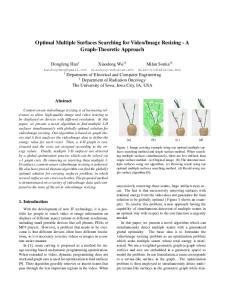
elements and protocol models which can be used as building blocks for the Monte Carlo simulation of networks. Since it is an open environment, new models can be created while existing library models can be easily modified. We developed the RTP/RTCP layer in OPNET, with the required subset of functions to run on the UDP layer. An MPT system with two paths was simulated. The two paths are identical in terms of available bandwidth and each path has three wireless hops, each modeled by the two-state model described in Section IV-B. In order to study the effect of the wireless channel, we have set the parameters such that the losses occur only due to uncorrectable channel errors and not due to, for example, buffer overflows or IP service rates. The video source application process opens multiple UDP (datagram) socket connections (equal to the number of paths) to the destination application process. As mentioned in Section II-B, at the source, traffic is distributed at the meta-RTP layer (i.e., using Option A in Fig. 2). The slices that reach the destination are resequenced at the meta-RTP layer and delivered in the correct order (indexed by the packet header) to the application. At the receiver, the slices coming from both paths are stored in a buffer. The application process (video decoder) reconstructs data from received slices and displays successive frames at regular intervals. The slices of a frame that are received past its display time are considered useless. Currently, we assume that the resequencing buffer requirement is not a constraint. That is, packet losses due to resequencing buffer overflows are not explicitly modeled. The losses due to excessive end of end delay (including resequencing delay) captures the effect of resequencing. V. RESULTS AND DISCUSSION Using the video source and the channel model described in the previous section, we have simulated the MD coder and the layered coder when both use MPT as the transport mechanism over two paths. In this study, the paths are used transparently (i.e., no information is kept/used regarding the “quality” of the path) either at the network or at the application layer, except when otherwise mentioned. In this section, we compare the end-to-end performance of these two systems. For the MDC case, we assume the two paths have similar error characteristics. For the layered coder, we consider the situation where one path has lower error rates than the other, and the base layer is delivered over the better path. This setup is intended to simulate either a situation where asymmetric paths naturally exist, or where ARQ and possibly a stronger FEC code are applied for the links carrying the base-layer packets. We vary the channel error characteristics by appropriately controlling the channel good and bad duration on each wireless hop, and compare the peak signal-to-noise ratios (PSNRs) of the received video stream under both schemes. In the following, we describe results from three sets of simulations. A. Performance Without Loss First, we compare the coding efficiency of the MD and layered coders. Table II includes the average PSNRs of the decoded frames without any transmission losses. The results are averaged over 25 frames for each sequence. As expected, the layered
784
IEEE TRANSACTIONS ON CIRCUITS AND SYSTEMS FOR VIDEO TECHNOLOGY, VOL. 12, NO. 9, SEPTEMBER 2002
TABLE II AVERAGE PSNR (dB) FOR THE CODED VIDEO CLIPS
(a)
(b)
(c)
(d)
(e)
(f)
(g)
(h)
(i)
Fig. 7. Reconstructed images assuming the base layer or one description is error-free. (a)–(c) Obtained with the layered coder when both layers are available (reconstructed images with the MD coder are similar when both descriptions are received). (d)–(f) Obtained with the layered coder, from the base layer only. (g)–(i) Obtained with the MD coder, from description one only, using the maximally smooth recovery method. PSNRs (in decibels) are Susie: (a) 41.42, (d) 34.61, and (g) 33.59; FlowerGarden: (b) 29.44, (e) 22.45, and (h) 21.90; and Football: (c) 32.70, (f) 25.99, and (i) 25.66.
coder yields a better quality (1.2–1.7 dB higher in PSNR) than the MD coder, under a similar data rate.2 This is because the layered coder employs a LOT basis that is optimized for coding efficiency, whereas the MD coder uses a basis that is optimized for a desired tradeoff between the coding efficiency and the reconstruction quality in the presence of transmission loss. Decoded images by the layered coder for sample frames are shown in Fig. 7(a). The images decoded by the MD coder are visually very similar to these images and, to save space, are not included. 2The base layer in the layered coder has a rate slightly higher than the rate of either description in the MD coder.
B. Performance With Guaranteed Base-Layer Delivery Next we compare the quality of reconstructed layer-coded images when only the base layer is available, with the MD-coded images when only one description is available. In the latter case, the maximally smooth image recovery method was used for reconstruction. Average PSNRs over 25 frames for each sequence are given in Table II. Sample reconstructed images are shown in Fig. 7(b) and (c). We can see that the reconstructed images from either base layer alone, or from a single description are quite satisfactory. The reconstructed images from the base layer in the layered coder are slightly better
GOGATE et al.: SUPPORTING IMAGE AND VIDEO APPLICATIONS IN A MULTIHOP RADIO ENVIRONMENT
785
TABLE III AVERAGE PSNR FOR MDC/MPT SCHEME UNDER VARIOUS CHANNEL ENVIRONMENTS. VIDEO CLIPS OF 10-s DURATION SENT AT 25 FPS
=
Channel parameters are p 0:005 (except for the second entry in the table, where p = 0:001) and q = 1: The numbers in parentheses denote the worst frame PSNR over the entire frequency.
than those from a single description in the MD coder, both in terms of the PSNR (0.2–0.8 dB better) and visual quality. Obviously, if one can design a network so that the path carrying the base-layer packets can be guaranteed error-free, the layered coder would be the best source coding scheme. However, if this were not possible or too costly, the situation would be different. Note that for the MD case, the reconstruction quality from either description is quite acceptable. On the other hand, for the layered coder, the reconstructed image from the enhancement layer alone will be unacceptable. As shown in the simulation results below, even a very small loss rate on the base layer will make the layered coder less desirable than the MD coder. C. Performance When Both Paths are Error Prone Tables III and IV show the PSNR values of reconstructed video frames using the MD and layered coders, respectively, when both paths are subjected to random packet losses. As described in Section IV-B, different packet loss rates are achieved by varying the “good” and “bad” durations on individual hops. and are the average good and bad state Assuming that is the average durations, respectively, on a wireless hop, packet duration, and is the packet loss probability in the good
state, then the probability that a packet is delivered successfully through this hop can be approximated by (3) If is the number of wireless hops on a path, and all the hops have the same channel model parameters, then the expected end-to-end (“e2e” in the equation) packet loss rate on this path is (4) For simplicity, we only consider the case where all the hops on a path can be modeled by the same parameters, and the number of hops ( ) is three in all the simulations described in this section. The actual packet loss rates produced by our simulations differ slightly from the one calculated according to (4). The loss rates listed in Tables III and IV are the measured end-to-end loss rates. For the MDC case, we assign the same parameters for all the hops on the two paths and the reported packet loss rates are the average of the end-to-end loss rates on the two paths. For the layered case, we fix the packet loss rate for the enhancement layer at about 25%, and vary the loss rates of the base layer from 0.8% to 7% by changing the combination of the “good” and
786
IEEE TRANSACTIONS ON CIRCUITS AND SYSTEMS FOR VIDEO TECHNOLOGY, VOL. 12, NO. 9, SEPTEMBER 2002
TABLE IV PERFORMANCE OF THE LAYERED CODER UNDER VARIOUS CHANNEL ENVIRONMENTS
=
The network scenario is asymmetric in terms of error characteristics on a path. Channel parameters are p 0:001 and q = 1: The average good and bad durations given are for the channel carrying the base layer. Those for the channel carrying the enhancement layer are fixed at 100 and 8 ms, respectively (except the first row, no-loss case).
“bad” durations in the underlying hops. As mentioned earlier, the radio channel is viewed as transitioning between the “good” and “bad” states. The underlying distribution is assumed to be exponential with a mean of average “good” duration and average “bad” duration, respectively. The set of simulated values for these are listed in Tables III and IV. In practice, one may use a combination of FEC and constrained ARQ (number of retransmissions limited to satisfy delay requirement) to achieve a desired packet loss rate that is lower than the raw packet loss rate. The packet loss rates quoted in this paper should be interpreted as the residual loss rates after the deployment of FEC and ARQ. To compare the effects of packet loss on reconstruction quality for the MD and layered systems, in Fig. 8, we show the PSNR versus average packet loss rate for the MD coder (labeled “MDC”) and the PSNR versus base-layer loss rate for the layered coder (labeled “LDC1”). We can see that the PSNR drops much faster in the layered system when the base-layer loss rate increases. Also, a very small base-layer loss rate will lead to a quality degradation equivalent to that in the MDC system at a much higher loss rate. For example, for “FlowerGarden” and “Football,” the PSNRs at a base-layer loss rate of 5% are similar to that by the MD coder at a loss rate of 13% on both paths. For “Susie,” a base-layer loss rate of 5% leads to the same distortion of the MD coder at a loss rate of 20%. One may argue that the above comparison is not fair because the enhancement-layer loss rate is, for most cases, higher than the loss rate in the MD system. In general, it is difficult to compare a system using symmetric paths and one using asymmetric paths. Ideally, we should compare them when the total resources used for source coding and error control are the same. This, however, depends on the error-control mechanisms used. One rea-
sonable assumption is that the total data rates (source rates plus FEC parity checking bits) used by the two systems are similar when the total source bit rates as well as average packet loss rates on the two paths are the same. In Fig. 8, we also show, for the layered coder, the PSNR versus the average of the packet loss rates in the base layer and enhancement layer (labeled “LDC2”). Because the simulated loss rates in the base layer is very small compared to that in the enhancement layer, the average loss rate is dominated by the loss rate in the enhancement layer, varying in a very small range. We can see that the layered coder is better than the MD coder when the average error rate is lower than a certain breakpoint. At relatively low error rates, the overall reconstruction quality is dominated by those blocks which do not experience transmission loss, and the layered coder yields better performance because it has a lower decoding distortion than the MD coder. At higher error rates, when the reconstruction quality of damaged blocks becomes the deciding factor, MDC becomes more effective. The break point depends on the underlying images. For images that are smooth (e.g., “Susie” and “Football”), the maximally smooth recovery method can conceal the error due to packet loss very well, so that the break point is relatively lower (13%). On the other hand, for images with many high-frequency details (e.g., “FlowerGarden”), this reconstruction method is less effective, and the break point is relatively higher (15%). As is well known, the average PSNR value among all frames does not correlate very well with the visual quality perception. Sometimes, a single bad frame in a video clip can attract viewer’s attention and make the sequence visually annoying. To take this into account, we also present in Tables III and IV the worst PSNR value among all frames. We can see that the layered coder performs worse than the MD coder under this
GOGATE et al.: SUPPORTING IMAGE AND VIDEO APPLICATIONS IN A MULTIHOP RADIO ENVIRONMENT
(a)
787
(b)
(c) Fig. 8. PSNR versus end-to-end packet loss rate for: (a) Susie, (b) FlowerGarden, and (c) Football. MDC: MD coder in symmetric path scenario, with the horizontal axis representing the average packet loss rate of the two paths. LDC1: Layered coder with the horizontal axis representing the base-layer packet loss rate. The enhancement layer packet loss rate is fixed at about 25%. LDC2: Layered coder with the horizontal axis representing the average packet loss rate of the base and enhancement layers.
measure at all error rates. Recall that, for the same loss pattern (i.e., the same set of coefficients are lost for each damaged block), the reconstruction quality using the maximally smooth recovery method is better with MD coder than with the layered coder. This is because the MD coder uses a LOT basis that intentionally introduces correlation among adjacent coefficient blocks, whereas the layered coder uses a LOT basis that minimizes the correlation. Also, for the same number of lost slices, the layered coder is more likely to experience cases when all the LOT coefficient blocks associated with a spatial block are lost so that this block cannot be concealed using the proposed reconstruction method. We call such a block undecodable. With the packetization format for the layered coder, a block becomes undecodable, if two overlapping slices, e.g., slices 1 and 3 in Fig. 5, are both lost, in either base layer alone or in both layers. On the other hand, for the MD coder, a block is undecodable only if all four overlapping slices, e.g., slices 1 and 3 in both
descriptions 1 and 2 are lost simultaneously. Frames with such undecodable blocks will have very low PSNR. Tables V and VI compare the percentage of undecodable blocks in the MDC and layered cases. We can see that the layered coder is worse than MDC under this measure, when the average loss rates are equal. To compare the visual quality when the average loss rate over two paths are equal, we show in Fig. 9 reconstructed images and their respective PSNRs for a selected frame in each sequence. For the layered coder, we manually set one slice in the base layer and ten slices in the enhancement layer as lost. For the MD coder, we set five slices in each description as lost. These slices are chosen so that they do not affect the same spatial blocks, which would be the usual case with our interleaved packetization mechanism. The lost slice in the base layer includes half of the coefficient blocks associated with the affected row of blocks. This leads to noticeable blurring of edges in the damaged area. On the other hand, the ten lost slices in the MD case affect ten
788
IEEE TRANSACTIONS ON CIRCUITS AND SYSTEMS FOR VIDEO TECHNOLOGY, VOL. 12, NO. 9, SEPTEMBER 2002
TABLE V PERCENTAGE OF UNDECODABLE BLOCKS FOR MDC/MPT SCHEME UNDER VARIOUS CHANNEL ENVIRONMENTS
TABLE VI PERCENTAGE OF UNDECODABLE BLOCKS FOR LAYERED SCHEME UNDER VARIOUS CHANNEL ENVIRONMENTS
The first number in parenthesis denotes the number of frames which has at least one undecodable block. The second number indicates the worst number of un-
The first number in parenthesis denotes the number of frames which has at least one undecodable block. The second number indicates the worst number of undecodable blocks in a frame. The total number of frames is 250; the number of blocks per frame is 1320 for “Susie” and “FlowerGarden” and 1260 for “Football”.
rows of blocks, but each with only a quarter of the coefficient blocks missing. Using our maximally smooth recovery method, the reconstructed image quality by the MD coder is slightly better, with more noticeable improvements in “Susie.” Note that visual quality in the above simulated error scenario depends on the location of the lost slices. In the worst case, the base layer can lose the same number of slices as each description in the MD coder. Figs. 10 and 11 show the reconstructed images in such cases. In Fig. 10, three slices are lost in both base layer and enhancement layer for the layered coder, and three slices are also lost in each description in the MD coder. In the latter case, the slices are chosen so that they cause the same set of coefficient blocks to be lost as in the layered case. Therefore, for both the layered and MDC cases, three rows have half of the coefficient blocks lost. Note that this co-location of lost slices in the MD case is rare in practice. We show this example to examine the reconstruction performance when the layered and MD coders have exactly the same loss pattern. The images in Fig. 10(a) are obtained by using the direct inverse for the layered case, which show the locations of the affected blocks. For the MD case, a direct inverse would yield similar results. Images in Fig. 10(b) and (c) are obtained with maximally smooth recovery method, for the layered and MD cases, respectively. We can see that the layered coder has more visible artifacts than the MD coder. Fig. 11 shows a similar case, but with eight slices lost on each layer/description. In this case, the layered coder is significantly worse than the MD coder.
decodable blocks in a frame. The total number of frames is 250; the number of blocks per frame is 1320 for “Susie” and “FlowerGarden” and 1260 for “Football”.
VI. CONCLUDING REMARKS We described a framework for video transport over an unreliable network using MPT and MDC and presented the meta-RTP protocol for transport control. We also described an MDC scheme using LOT and an associated image-reconstruction scheme. We simulated an MDC–MPT system which has two paths with the same capacity and error characteristics. The two descriptions have similar bit rates. As a comparison, we also implemented a layered coder, and examined its performance when the two paths carrying the base and enhancement layers have asymmetrical error characteristics. The conclusion from our simulation results is that when the path carrying the base layer can be guaranteed error-free or with very low error rates, the layered coder gives a better overall performance. Passing this break point, the MD coder becomes more effective. Considering the high error rates typical for a wireless hop, which become even more dominant in a multihop scenario, the proposed MDC–MPT system appears to be a more attractive approach than the layered coding approach. One way to guarantee error-free transmission of base layer packets is by using ARQ. This however will introduce delay, which depends on the round-trip time (RTT) of the path between the sender and the receiver. Simulation studies presented in [43] showed that MDC with no ARQ performs better than LC with ARQ, unless the RTT is very short. Even when the RTT is short, MDC is better when the latency requirement of the underlying application is stringent. Although a very different MD coder was used, their conclusions are consistent with ours: under long RTTs or low-delay requirements, one cannot use ARQ indefinitely, so that the base layer cannot be delivered error-free or with very low error rates.
GOGATE et al.: SUPPORTING IMAGE AND VIDEO APPLICATIONS IN A MULTIHOP RADIO ENVIRONMENT
789
(a)
(b)
(c)
(d)
(e)
(f)
Fig. 9. Reconstructed images when the base layer loss rate is much lower than either description. (a)–(c) Obtained with the layered coder, when the base layer and enhancement layer lost one and ten slices, respectively. (d)–(f) Obtained with the MD coder, when each description lost five slices (each affecting a different row). The maximally smooth recovery method is applied in all cases to repair damaged blocks. PSNRs (in decibels) are “Susie:” (a) 36.27 and (d) 36.68; “FlowerGarden:” (b) 25.70 and (e) 24.68; and “Football:” (c) 28.39 and (f) 28.37.
(a)
(b)
(c)
(d)
(e)
(f)
(g)
(h)
(i)
Fig. 10. Reconstructed images when the base-layer loss rate is the same as for either description. (a)–(c) Obtained with the layered coder using direct inverse reconstruction, when both the base layer and enhancement layer lost three slices (these images are meant to show locations of damaged blocks). (d)–(f) Obtained with the layered coder using the maximally smooth recovery method. (g)–(i) Obtained with the MD coder using the maximally smooth recovery method, when both descriptions lost three slices [each pair of two slices affecting the same row, so that the loss pattern is the same as in (a)–(c)]. PSNRs (in decibels) are: Susie: (a) 27.18, (d) 36.23, and (g) 37.62; FlowerGarden: (b) 20.67, (e) 26.41, and (h) 26.37; and Football: (c) 24.45, (f) 27.54, and (i) 28.79.
790
IEEE TRANSACTIONS ON CIRCUITS AND SYSTEMS FOR VIDEO TECHNOLOGY, VOL. 12, NO. 9, SEPTEMBER 2002
(a)
(b)
(c)
(d)
(e)
(f)
(g)
(h)
(i)
Fig. 11. Reconstructed images when the base layer loss rate is the same as for either description and the loss rate is very high. (a)–(c) Obtained with the layered coder using direct inverse reconstruction, when both the base layer and enhancement layer lost eight slices. (d)–(f) Obtained with the layered coder using the maximally smooth recovery method. (g)–(i) Obtained with the MD coder using the maximally smooth recovery method, when both descriptions lost eight slices [each pair of two slices affecting the same row, so that the loss pattern is the same as in (a)–(c)]. PSNRs (in decibels) are: Susie: (a) 22.05, (d) 32.16, and (g) 35.64; FlowerGarden: (b) 17.94, (e) 21.32, and (h) 23.99; and Football: (c) 21.19, (f) 24.23, and (i) 27.14.
After the initial submission of this paper, several proposals of combining MDC with MPT for multimedia transport over the Internet have appeared. For example, Apostolopoulos [44] proposed to code a video source into MDs using temporal frame subsampling [45] and transmit them over multiple paths through either IP source routing or relay service. The analysis and simulation results showed that by using multiple paths, the compressed stream sees an “averaging behavior" in terms of packet loss and delay jitter, which is much better than the behavior of individual paths. Significant gain was observed over a scheme that uses a conventional single-description coder and a single-path transmission scheme. Liang et al. [46] proposed to deliver voice over IP by combining an MDC scheme that also relies on temporal subsampling [47] and MPT using a designated relay service. It was shown that path diversity can average out the delay jitter on each path so that the impact of packet loss due to excessive delay is significantly reduced. These studies are complementary to the work reported here, which focuses on combining MDC and MPT for image and video transmission over wireless networks. For the Internet, the benefit of path diversity lies mainly in reducing the packet loss due to delay jitter caused by traffic congestion. For the
wireless network, MPT helps greatly in mitigating the effect of link failures and packet losses due to high bit-error rates. We are in the process of extending this work in the following ways. First, the MD coder can be modified to produce layers of different priority in each description. This will enable the adaptation of the rate of each description in response to the change in the error rates and usable bandwidth on each path. Second, the MD and layered coders simulated here process each video frame independently. To achieve higher coding efficiency, motion-compensated temporal prediction should be incorporated. We need to simulate such coders, e.g., those reported in [45], [48]–[50], and evaluate the error-propagation effect due to temporal prediction. Third, we will simulate the system with heterogeneous paths in terms of error rates and available bandwidth. The effect of the background traffic on the number of the packets that miss the deadline at the destination will be studied. We will further extend our work on RTCP Receiver Reports and source rate adaptation and adaptive routing in response to these reports. Fourth, we will compare the performance of the MDC–MPT and layered systems with link layer or end-to-end ARQ, at least for the base-layer slices. The number of retransmissions allowed will be limited by the maximum allowable delay and the decoder
GOGATE et al.: SUPPORTING IMAGE AND VIDEO APPLICATIONS IN A MULTIHOP RADIO ENVIRONMENT
buffer size. Finally, in this paper, we have spread the traffic onto multiple paths based on the available bandwidth on that path. Another way of extending this work would be to consider a path quality metric which is based on a function of path bandwidth, path latency, and average error rate. REFERENCES [1] Y. Q. Zhang et al., “Layered image transmission over cellular radio channels,” IEEE Trans. Veh. Technol., vol. 43, pp. 786–794, Aug. 1994. [2] M. Khansari et al., “Low bit rate video transmission over fading channels for wireless microcellular systems,” IEEE Trans. Circuits Syst. Video Technol., vol. 6, pp. 1–11, Feb. 1996. [3] E. Ayanoglu, R. Pancha, A. R. Reibman, and S. Talwar, “Forward error control for MPEG-2 video transport in a wireless ATM LAN,” ACM/Baltzer Mobile Networks and Applicat., vol. 1, no. 3, pp. 245–258, Dec. 1996. [4] A. Alwan, R. Bagrodia, N. Bambos, M. Gerla, L. Kleinrock, J. Short, and J. Villasenor, “Adaptive mobile multimedia networks,” IEEE Pers. Commun., vol. 3, pp. 34–51, Apr. 1996. [5] J. K. Wolf, A. Wyner, and J. Ziv, “Source coding for multiple descriptions,” Bell Syst. Tech. J., vol. 59, pp. 1417–1426, Oct. 1980. [6] L. Ozarow, “On a source coding problem with two channels and three receivers,” Bell Syst. Tech. J., vol. 59, pp. 1909–1921, Dec. 1980. [7] A. A. El Gamal and T. M. Cover, “Achievable rates for multiple descriptions,” IEEE Trans. Inform. Theory, vol. IT-28, pp. 851–857, 1982. [8] V. A. Vaishampayan, “Design of multiple description scalar quantizer,” IEEE Trans. Inform. Theory, vol. 39, pp. 821–834, May 1993. [9] Y. Wang, M. Orchard, V. Vaishampayan, and A. Reibman, “Multiple description coding using pairwise correlating transforms,” IEEE Trans. Image Processing, vol. 10, pp. 351–366, Mar. 2001. [10] D. Chung and Y. Wang, “Multiple description image coding using signal decomposition and reconstruction based on lapped orthogonal transforms,” IEEE Trans. Circuits Syst. Video Technol., vol. 9, pp. 895–908, Sept. 1999. [11] V. K. Goyal and J. Kovacevic, “Generalized multiple description coding with correlating transforms,” IEEE Trans. Inform. Theory, vol. 47, pp. 2199–2224, Sept. 2001. [12] S. D. Servetto, K. Ramchandran, V. Vaishampayan, and K. Nahrstedt, “Multiple description wavelet based image coding,” in Proc. ICIP’98, pp. 659–663. [13] H. Jafarkhani and V. Tarokh, “Multiple description trellis coded quantization,” IEEE Trans. Commun., vol. 47, pp. 799–803, June 1999. [14] V. K. Goyal, “Multiple description coding: Compression meets the network,” IEEE Signal Processing Mag., vol. 18, pp. 74–93, Sept. 2001. [15] N. F. Maxemchuck, “Dispersity routing in store and forward networks,” Ph.D. dissertation, Univ. Pennsylvania, Philadelphia, May 1975. [16] T. T. Lee and S. C. Liew, “Parallel communications for ATM network control and management,” in Proc. GLOBECOM’93, Nov. 1993, pp. 442–446. [17] N. T. Plotkin and P. P. Varaiya, “Performance analysis of parallel atm connections for gigabit speed applications,” in Proc. INFOCOM’93, pp. 1186–1193. [18] E. Ayanoglu, I. Chih-Lin, R. Gitlin, and J. Mazo, “Diversity coding for self-healing and fault tolerant communication networks,” IEEE Trans. Commun., vol. COM-41, pp. 1677–1688, Nov. 1993. [19] R. Krishnan and J. A. Silvester, “Choice of allocation granularity in multipath source routing schemes,” in Proc. INFOCOM’93, Mar. 1993, pp. 322–329. [20] Z. J. Haas and M. R. Pearlman. (1999, Dec.) The Zone Routing Protocol (ZRP) for ad hoc networks, Internet draft. [Online]. Available: hdraftietf-manet-zone-zrp-02.txti [21] N. Shacham and P. King, “Architectures and performance of multichannel multihop packet radio networks,” IEEE J. Select. Areas Commun., vol. SAC-5, pp. 1013–1025, July 1987. [22] L. Hu, “Distributed code assignments for CDMA packet radio networks,” IEEE/ACM Trans. Networking, vol. 1, pp. 668–677, Dec. 1993. [23] C-L. I and R. D. Gitlin, “Multicode-CDMA wireless personal communication networks,” in Proc. ICC’95, pp. 1060–1063. [24] S. Chowdhury, “Distribution of the total delay of packets in virtual circuits,” in Proc. INFOCOM’91, Apr. 1991, pp. 911–918.
791
[25] A. Jean-Marie and L. Gun, “Parallel queues with resequencing,” J. Assoc. Comput. Mach., vol. 40, no. 5, pp. 1188–1208, 1993. [26] N. Gogate and S. S. Panwar, “On a resequencing model for high speed networks,” in Proc. INFOCOM’94, pp. 40–47. , “Assigning customers to two parallel servers with resequencing,” [27] in Proceedings of the 1995 Conference on Information Sciences and Systems. Baltimore, MD: Johns Hopkins Univ. Press, Mar. 1995. [28] H. Schulzrinne, S. Casner, R. Frederick, and V. Jacobson, “RTP: A transport protocol for real time applications,”, RFC 1889, Internet Request for Comments, Jan. 1996. [29] R. J. Clarke, Transform Coding of Images. London, U.K.: Academic, 1985. [30] P. Cassereau, D. Staelin, and G. D. Jager, “Encoding of images based on a lapped orthogonal transform,” IEEE Trans. Commun., vol. 37, pp. 189–193, Feb. 1989. [31] W. B. Pennebaker and J. Mitchell, JPEG—Still Image Data Compression Standard. New York: Van Nostrand, 1993. [32] Y. Wang, Q.-F. Zhu, and L. Shaw, “Maximally smooth image recovery in transform coding,” IEEE Trans. Commun., vol. 41, pp. 1544–1551, Oct. 1993. [33] S. S. Hemami, “Reconstruction-optimized lapped orthogonal transfoms for robust image transmission,” IEEE Trans. Circuits Syst. Video Technol., vol. 6, pp. 168–181, Apr. 1996. [34] D. Chung and Y. Wang, “Lapped orthogonal transforms designed for error resilient image coding,” in Proc. IEEE Int. Conf. Image Processing (ICIP2000), Vancouver, BC, Canada, Oct. 2000. , “Lapped orthogonal transforms designed for error resilient image [35] coding,” IEEE Trans. Circuits Syst. Video Technology, vol. 12, pp. xxx–xxx, Sept. 2002. [36] E. N. Gilbert, “Capacity of a burst-noise channel,” Bell Syst. Tech. J., vol. 39, no. 9, pp. 1253–1265, Sept. 1960. [37] E. O. Elliott, “Estimates of error rates for codes on burst-noise channels,” Bell Syst. Tech. J., vol. 42, no. 9, pp. 1977–1997, Sept. 1963. [38] B. G. Haskell, A. Puri, and A. N. Netravali, Digital Video: An Introduction to MPEG-2. New York: Chapman & Hall, 1997. [39] G. L. Stuber, Principles of Mobile Communication. Norwell, MA: Kluwer, 1996. [40] W. C. Jakes, Microwave Mobile Communications. Piscataway, NJ: IEEE Press, 1993. [41] “OPNET Simulation and Modeling Tool,” Mil3 Inc.. [42] N. Gogate and S. S. Panwar, “Supporting applications in a mobile multihop radio environment using route diversity—Part I: Non-real time data,” in Proc. IEEE Int. Conf. Commun., June 1998, pp. 802–806. [43] R. Singh, A. Ortega, L. Perret, and W. Jiang, “Comparison of multiple description coding and layered coding based on network simulations,” in Proc. SPIE Conf. Visual Communication and Image Processing, Apr. 2000, pp. 929–939. [44] J. G. Apostolopoulos, “Reliable video communication over lossy packet networks using multiple state encoding and path diversity,” in Proc. SPIE Conf. Visual Communication and Image Processing, Jan. 2001, pp. 392–409. , “Error resilient video compression via multiple state streams,” in [45] Int. Workshop on Very Low Bitrate Video Coding (VLBV99), Oct. 1999, pp. 168–171. [46] Y. J. Liang, E. G. Steinbach, and B. Girod, “Multi-stream voice over IP using packet path diversity,” in IEEE Multimedia Signal Processing Workshop (MMSP01), Sept. 2001, pp. 555–560. [47] W. Jiang and A. Ortega, “Multiple description speech coding for robust communication over lossy packet networks,” in Proc. IEEE Int. Conf. Multimedia and Exposition (ICME2000), vol. 1, Aug. 2000, pp. 444–447. [48] S. Wenger, “Video redundancy coding in H.263+,” in Audio Visual Services ver Packet Networks Workshop, Aberdeen, U.K., Sept. 1997. [49] A. Reibman, H. Jafarkhani, Y. Wang, and M. Orchard, “Multiple description coding for video using motin compensated prediction,” IEEE Trans. Circuits Syst. Video Technol., vol. 12, pp. 193–204, Mar. 2002. [50] Y. Wang and S. Lin, “Error resilient video coding using multiple description motion compensation,” IEEE Trans. Circuits Syst. Video Technol., vol. 12, pp. 438–452, June 2002. [51] N. Gogate and S. S. Panwar, “Assigning customers to two parallel servers with resequencing,” IEEE Commun. Lett., vol. 3, pp. 119–121, Apr. 1999.
792
IEEE TRANSACTIONS ON CIRCUITS AND SYSTEMS FOR VIDEO TECHNOLOGY, VOL. 12, NO. 9, SEPTEMBER 2002
Nitin Gogate (S’96–M’92) received the B.E. degree from Pune University, India, the M.Tech. degree in electrical engineering from the Indian Institute of Technology, Kanpur, India, and the Ph.D. degree in electrical engineering from Polytechnic University, Brooklyn, NY. He is currently a Systems Engineer at Fujitsu Network Communications, Pearl River, NY. His research interests include Internet QoS, multimedia services over wireless networks, and performance analysis and modeling of next-generation access networks.
Doo-Man Chung was born in Seoul, Korea, in 1957. He received the B.S. degree from Ajou University, Suwon, Korea, in 1983, and the M.S. and Ph.D. degrees from Polytechnic University, Brooklyn, NY, in 1990 and 2000, respectively, all in electrical engineering. He was with the Computer Division, GoldStar Company, Seoul, Korea (1983–1986), Datacom Inc., Holmdel, NJ (1991–1992), and MTA New York City Transit (1994–1995). From 1996 to 2000, he was a Research Assistant in the Department of Electrical Engineering, Polytechnic University. Since 2001, he has been a Traffic Signal Designer in the Signal Division, NYC Department of Transportation (DOT). His research interests include signal and image processing, with emphasis on image reconstruction from low-bit-rate coding data.
Shivendra S. Panwar (S’82–M’85–SM’00) received the B.Tech. degree in electrical engineering from the Indian Institute of Technology, Kanpur, India, in 1981, and the M.S. and Ph.D. degrees in electrical and computer engineering from the University of Massachusetts, Amherst, in 1983 and 1986, respectively. He is currently a Professor in the Electrical and Computer Engineering Department, Polytechnic University, Brooklyn, NY. From 1981 to 1985, he was a Research Assistant at the University of Massachusetts. He then joined the Department of Electrical Engineering, Polytechnic Institute of New York (now Polytechnic University). He is currently the Director of the New York State Center for Advanced Technology in Telecommunications (CATT). He spent the summer of 1987 as a Visiting Scientist at the IBM T. J. Watson Research Center, Yorktown Heights, NY, and has been a Consultant to AT&T Bell Laboratories, Holmdel, NJ. His research interests include the performance analysis and design of networks. His current work includes protocol analysis, traffic and call admission control, switch performance, and multimedia transport over wireless networks. He is co-editor of two books, Network Management and Control, Vol. II (New York: Plenum, 1994) and Multimedia Communications and Video Coding (Norwell, MA: Kluwer, 1996). Dr. Panwar has served as the Secretary of the Technical Affairs Council of the IEEE Communications Society (1992–1993) and is a member of the Technical Committee on Computer Communications.
Yao Wang (M’90–SM’98) received the B.S. and M.S. degrees in electronic engineering from Tsinghua University, Beijing, China, in 1983 and 1985, respectively, and the Ph.D. degree in electrical and computer engineering from the University of California, Santa Barbara, 1990. Since 1990, she has been with the faculty of the Polytechnic University, Brooklyn, NY, where she is presently Professor of Electrical and Computer Engineering. She was on sabbatical leave at Princeton University, Princeton, NJ, in 1998, and was a Visiting Professor at the University of Erlangen, Erlangen, Germany, in the summer of 1998. She was a Consultant with AT&T Laboratories–Research (formerly AT&T Bell Laboratories), from 1992 to 2000. Her research areas include video communications, multimedia signal processing, and medical imaging. She is the leading author of the textbook Video Processing and Communications (Englewood Cliffs, NJ: Prentice-Hall, 2002), and has authored or coauthored over 100 papers in journals and conference proceedings. Dr. Wang has served as an Associate Editor for IEEE TRANSACTIONS ON MULTIMEDIA and IEEE TRANSACTIONS ON CIRCUITS AND SYSTEMS FOR VIDEO TECHNOLOGY. She received New York City Mayor’s Award for Excellence in Science and Technology in the Young Investigator Category in 2000.