Journal of Electrical Engineering The Institution of Engineers, Bangladesh Vol. EE 31, No. I & II, December 2004
Sliding Mode Speed Controller of a D.C Motor Drive Mohammed Golam Sarwer, Md. Abdur Rafiq and B.C. Ghosh Department of Electrical & Electronic Engineering Khulna University of Engineering & Technology Khulna-9203, Bangladesh E-mail:
[email protected]
ABSTRACT This paper presents a separately excited DC motor speed control scheme using sliding mode control technique. The mathematical model suitable for sliding mode control is derived. A straight-line switching surface is proposed, and a controller is designed to guarantee that the operation on sliding surface is reached and sustained. The simulation results and experimental results are presented. The performance of the proposed controller is evaluated under various operating conditions and compared with conventional PI controller. Key words: Sliding mode control, switching surface. 1. INTRODUCTION Direct current motors have occupied a wide spectrum of applications for variable speed drives, because of their simplicity and versatility of control. In the past three decades, nonlinear and adaptive control methods have been used extensively to control DC and brushless dc motor drives [1-4]. In these methods, the state estimation and parameter identification are based on and limited to linear models. As the model deviates from the physical system, the performance of the control degrades. Sliding mode control is one of the effective and robust means of controlling the nonlinear system. The theory of sliding mode control has been developed for a long time and has recently been applied to the control of a wide range of processes [5-9]. There are many excellent properties in sliding mode control, such as, insensitivity to parameter variations and disturbances, no requirement of the accurate model of the control system, and simple realization of the control algorithm. When a sliding mode is once achieved, the state trajectory slides along a switching hyper surface to the phase space origin. This paper presents a DC motor speed control using sliding mode control law. A straight-line switching surface is proposed based on the existence of a certain positive define function. The
feature of this switching surface is that when the rotor speed response reaches its steady state value, the switching surface become linear. 2. DYNAMIC MODEL OF A SEPARATELY
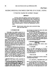
EXCITED DC MOTOR A separately excited dc motor has the simplest decoupled electromagnetic structure. A schematic diagram of the electrical network of the machine is shown in Fig.1.
Ra V
Lf I f
La
+ ωm T e ea M J -
B
Rf
Vf
Tl
Fig. 1: Schematic diagram of a separately excited dc motor. The field excitation is normally kept constant to produce rated flux. The armature current is controlled to generate desired electromagnetic torque and the armature voltage is controlled for the load.
Sarwer et. al : J. Elec. Engg., Instn. Engrs., Bangladesh, 31( I & II), December 2004
system is determined by this switching surface if the sliding mode exists. First, the speed error is introduced.
Assuming constant field excitation the armature circuit electrical equation is written as V=
R a i a + La
di a dt
+ k bω m
(1)
e(k ) = ω ref (k ) − ω (k )
Where, V = Applied Voltage, R a = Lumped armature resistance, La = Equivalent armature inductance, i a = current flowing through armature
Where, ω ref (k )
A straight-line switching surface σ is introduced in terms of speed error and its derivative is given below [10]:
The dynamics of the mechanical system is given by the following torque balance equation
dw m + B ω m (2) dt
σ = e( k ) + C
Where, Te = developed torque, Tl = load torque, J = moment of inertia, B = damping constant, and K t = motor constant. Equations 1 and 2 are rearranged to obtain
Kω dia v Ra = − ia − b m La dt La La
(3)
dω m K t ia Tl B = − − ( )ω m dt J J J
(4)
Where,
V − I a Ra Kb
or, Ω m =
RT V − a e Kb Kb Kt
de(k ) dt
(8)
C > 0 is a strictly positive real constant
de(k ) is the derivative of speed error at k-th and dt
sampling interval. The above equation characterizes the deviations from the desired state. If the sliding surface is reached and sustained, then σ = 0 . The speed error-switching surface is a straight line in the phase plane as shown in Fig 2.
σ >0
Under steady state condition the speed of the motor is given by
Ωm =
are the respective
responses of the desired reference track and actual rotor speed, at the k th sampling interval and e(k ) is the speed error.
circuit, K b = motor constant and ω m = motor speed.
Te = K t i a = Tl + J
and ω (k )
(7)
σ <0
(5)
de(k ) dt
σ >0 e(k )
(6)
σ <0
Equation 6 indicates that controlling the armature input voltage effectively controls the speed of the motor. It is evident from (3) and (4) that variation of parameters and constants converts the system a nonlinear one.
σ =0
Fig. 2: Switching surface in the phase plane. For any point at the right side the switching surface σ > 0 and left side the switching surface σ < 0 , whereas, on the sliding ( switching ) surface σ = 0 .
3. SLIDING MODE CONTROLLER DESIGN
The simplest control input to reach σ = 0 through equivalent control [10] is given by:
The principle of designing sliding mode control law for arbitrary-order plants is to make the error and derivative of error of a variable is forced to zero [10]. In the DC motor system the speed error and its derivative are the selected coordinate variables those are forced to zero. Switching surface design consists of the construction of the switching function. The transient response of the
u = −1 forσ > 0 u = +1 forσ < 0 Where u is the equivalent control signal compensating the estimated unknown dynamics.
46
Sarwer et. al : J. Elec. Engg., Instn. Engrs., Bangladesh, 31( I & II), December 2004
adjusted to positive and negative voltages for -1 and +1 values.
The complete control circuit block diagram of the proposed system is shown in Fig. 3. Here u is
Disturbance
w ref (k ) +
e(k ) -
d dt
C
σ
+ +
+
u +
Motor
Switching Surface
w(k )
Fig. 3: Block diagram of sliding mode speed control system. Speed in rad/sec
4. SIMULATION RESULTS The performance evaluation of the proposed speed controller was made by simulation on a digital computer environment. Parameters of the DC motor drive used for simulation are listed below:
250 200 150 100
Armature resistance, Armature reactance, Moment of inertia, Damping constant, Load torque,
Ra= 7.56 Ω La= 0.055 henry J = 0.136 Kg-m2 B=0.0002 Kg-m2 Tl = 1 N-m.
50 0
10
15
20
Time in sec
Fig. 4(b): speed of the PI controller for a disturbance in speed of ± 3%.
Equations (3) and (4) are solved simultaneously using the Runge-Kutta-Gill method. Sampling time of the speed controller is 5 ms. The performance of proposed controller was compared with conventional PI controller.
Figure 5 shows the output voltage and speed of sliding mode controller for a random disturbance in speed measurement (output) of ± 3%. Percentage of Voltage
Figure 4 shows the output voltage and speed of PI controller for a random disturbance in speed measurement (output) of ± 3%.
Input Control Voltage in volts
5
0
600 500
1.0 0.5 0.0 -0.5 -1.0
400
10.9
300
11.0
11.1
11.2
Time in sec
200
Fig. 5(a): Percentage of voltage of the Sliding Mode Controller for a disturbance in speed of ± 3 % (Base value of voltage= 220 volts).
100 00
5
10
15
20
Time in sec
The steady state speed of sliding mode controller is very close to reference speed as compared to PI controller. The sliding mode controller shows better performance.
Fig. 4(a): Control signal voltage of the PI controller for a disturbance in speed of ± 3%.
47
Percentage of voltage
Sarwer et. al : J. Elec. Engg., Instn. Engrs., Bangladesh, 31( I & II), December 2004
Speed in rad/sec
250 200 150 100 50 0
5
0
10
15
1.0 0.5 0.0 -0.5
-1.0 10.9 10.95 11.00 11.05 11.10 11.15 11.20
20
Time in sec
Time in sec
Input Control Voltage in volts
Speed in rad/sec
Fig. 5(b): Speed of the Sliding Mode Controller for a disturbance in speed of ± 3%. 60 0 40 0
250 200 150 100 50
20 0
0 0
0 200 0
5
2
4
6
8
1 0
1 2
1 4
20
15
Fig.7: (a), (b) Control signal voltage, (c) speed of the Sliding Mode Controller for different set speeds.
(a)
300
250
Speed in rad/sec
250 200 150 100 50 00
200 150 100
50
5
10
Time in sec
15
20
0 0
5
(b)
10
15
20
Time in sec
Fig. 6: (a) Control signal voltage and (b) speed of the PI controller for different set speeds.
(a)
300 250
Speed in rad/sec
Percentage of voltage
10
Time in sec
(c)
Time in sec Speed in rad/sec
(b)
300
1.0
200
0.5
150 100
0.0
50
-0.5 0
50
100
150
200
Time in sec
-1.0 8.90 8.95
0
9.00
9.05
9.10
(b)
9.15 9.20
Time in sec
Fig. 8: Speed response of PI controller (a) for set speed 250 rad/sec (b) for different set speeds.
(a)
48
Sarwer et. al : J. Elec. Engg., Instn. Engrs., Bangladesh, 31( I & II), December 2004
Figures (6) and (7) show the controller performance for different set speeds. Initially the reference speed was 250 rad/sec. After 09 seconds the reference speed was set at 150 rad/sec. When the motor speed reaches to set speed, the reference speed was set at new value of 300 rad/sec. For both controllers, speed is changed gradually with change in reference speed.
6. CONCLUSIONS A new switching surface is proposed for a DC motor speed control system. The simulation and experimental results show that the sliding mode controller has the fast speed response, determined by the switching surface, and is obtained without overshoot. By applying random speed disturbance up to ± 3%, the speed response of PI controller is slightly oscillatory, whereas the speed response of sliding mode controller is perfectly smooth. The control system is insensitive to the motor parameter variation and load torque disturbances.
5. EXPERIMENTAL RESULTS To verify the proposed concept a laboratory setup was made with a DC motor drive. Figures (8) and (9) show the speed response of PI controller and sliding mode controller respectively. It was found that step changes of speed for PI controller where speed change gradually for sliding mode controller.
REFERENCES [1] E. Cerruto, A. Consoli , A. Raciti, and A. Testa, “ A robust adaptive controller for PM motor drives in robotic application.” IEEE Trans. On Ind. Applicat., vol. 28, pp. 448-454, Mar/April 1992. [2] N.Hemati,J. Thorp, and M.C. Leu, “Robust nonlinear control of brushless dc motors for directdrive robotic applications,” IEEE Trans. Ind. Electron., vol. 3, pp. 562-575, June 1990. [3] B.Grcar, P.Cafuta, and M.Znidaric, “Practical robust stabilization of PAMC servo drive based on continuous variable structure control,” IEEE Trans. Energy Conversion, vol.11,pp. 708-714, Dec 1996. [4] N.Matsui and H. Ohashi ,”DSP-based adaptive control of a brushless motor,” IEEE Trans. Ind. Applicat., vol.28,pp.448-454,Mar./Apr. 1992. [5] A. Sabanovic and B.B. Izosimov, “ Application of sliding modes to induction motor control,” IEEE Trans. Ind. Appl., vol. 1A-17, no. 1,pp. 41-49, Jan/Feb 1981. [6] A. Sabanovic and F. Bilalovic, “ Sliding mode control of AC drives,” IEEE Trans. Ind. Appl. ,Vol. 25, no. 1, pp. 70-75, Jan/Feb 1989 [7] Rogelio Soto and Kai S. Yeung, “ Sliding mode control of Induction Motor without flux measurement,” Conference record of IEEE Industry application Annual meeting, 1992, pp. 1724-1731. [8] J.Y. Hung, W.Gao and J.C Hung, “ Variable structure control: A survey.” IEEE Trans. Ind. Electron. , vol. 40, no. 1, pp. 2-22, Feb 1993. [9] Weiwei Qi, Induction Motor DSliding Mode Control, Ph.D. Dissertation, University of Missouri-Colombia, 1993 [10] V.I. Utkin, “ Sliding Mode Control.” English translation, Mir publishers, 1978.
250
Speed in rad/sec
200
150
100
50
0
0
20
40
60
80
100
120
Time in sec
(a) Fig. 9(a): Speed response of Sliding Mode Controller for set speed 250 rad/sec.
Speed in rad/sec
25 0 20 0 15 0 10 0 5 0 0
0
2 0
4 0
6 0
Time in sec
8 0
10 0
12 0
(b) Fig. 9(b): Speed response of Sliding Mode Controller for different set speeds.
49