USO0RE37354B1
(19)
United States
(12) Reissued Patent
(10) Patent Number: US (45) Date of Reissued Patent:
Welch et al. (54) SEMICONDUCTOR LASER WITH
OTHER PUBLICATIONS
INTEGRAL SPATIAL MODE FILTER
Ikeda, Japanese patent abstract of 2—166785, “semiconduc
(75) Inventors: David F. Welch, Menlo Park; David G.
Mehuys, Sunnyvale; Donald R. Scifres, San Jose, all of CA (US)
tor laser”, Mitsubishi Electric Corp. Jun. 1990.
Mittelstein et al., “Broadband tunability of gain—?attened quantum Well seimconductor lasers With an external grat
ing,” Appl. Phys. Lett., 54(12), 1092—1094, Mar. 20, 1989. Notomi et al., “Broad—Band Tunable TWo—Section Laser
(73) Assignee: SDL, Inc., San Jose, CA (US)
Diode With External Grating Feedback,” IEEE Photonics Technology Letters, vol. 2, No. 2, pp. 85—87, Feb. 1990. Schremer et al., “Single—frequency tunable external—cavity semiconductor laser using an electro—optic birefringent
(21) Appl. No.: 09/418,905 (22) Filed:
RE37,354 E Sep. 4, 2001
Oct. 15, 1999
modulator,”Appl. Phys. Lett., 55(1), pp. 19—21, Jul. 3, 1989. 5,602,864
Schremer et al., “External—Cavity Semiconductor Laser With 1000 GHZ Continuous Piezoelectric Tuning Range,” IEEE Photonics Technology Letters, vol. 2, No. 1, pp. 3—5,
Issued:
Feb. 11, 1997
Jan. 1990.
Appl. No.:
08/393,136
Filed:
Feb. 21, 1995
Related U.S. Patent Documents Reissue of:
(64) Patent No.:
(List continued on next page.)
Primary Examiner—Hemang Sanghavi
U.S. Applications: (62)
Division of application No. 08/263,190, ?led on Jun. 21, 1994, now Pat. No. 5,592,503, which is a division of
application No. 08/001,735, ?led on Jan. 7, 1993, now Pat.
No. 5,392,308. (51)
Int. Cl.7 ...................................................... .. H01S 3/19
(52)
U.S. Cl. ............................... .. 372/50; 372/46; 372/96;
(58)
Field of Search ................................ .. 372/44—46, 49,
372/101; 372/102
372/50, 97, 101, 102, 99, 100, 96, 20, 32, 98
(56)
References Cited
4,251,780
2/1981
Scifres et a1. .
4,349,905
9/1982
Ackley
4,369,513
1/1983
Umeda et a1. ....................... .. 372/46
.. 331/945 . . . . ..
372/46
(List continued on next page.) FOREIGN PATENT DOCUMENTS 0461632 2-82593
(57)
ABSTRACT
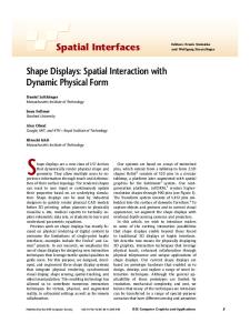
A semiconductor laser having a light amplifying diode heterostructure With a ?ared gain region in an external resonant cavity. The ?ared gain region has a narroW aperture end Which may be coupled to a single mode Waveguide and a Wide output end. A light emitting surface of the hetero structure proximate to the Wide end of the ?ared gain region is partially re?ective and combines With an external re?ector to form a resonant cavity that is effectively unstable. The intracavity light-emitting surface proximate to the narroW aperture end is antire?ection coated. The external re?ector may be a planar mirror or a grating re?ector. A lens or an
U.S. PATENT DOCUMENTS
..........
(74) Attorney, Agent, or Firm—Gallagher & Lathrop; Timothy J. Lane, Esq.; David N. Lathrop, Esq.
optical ?ber may couple the aperture end of the ?ared gain region to the external re?ector. Frequency-selective feed back is provided by orienting the grating re?ector or pro viding a prism in the cavity in front of the external planar mirror. Other ?ltering elements may also be placed in the external cavity. The ?ared gain region and Waveguide may be differentially pumped or modulated With current provided by separate contacts.
12/1991 (EP) . 3/1990 (JP) .
59 Claims, 12 Drawing Sheets
[33 37
35
43
39
41
US RE37,354 E Page 2
Ludeke et al., “Single Mode GaAs Laser in External Cav
US. PATENT DOCUMENTS 4,446,557
5/1984 Figueroa .............................. .. 372/45
4,689,797
8/1987
Olshansky ..
.... .. 372/45
4,783,788
11/1988
Gordon
. . . . ..
372/45
4,791,648
12/1988
Vojak et al.
. . . ..
372/46
4,791,649
12/1988 Yamamoto et al.
4,794,346
12/1988
4,796,273
......
.......
372/48
Miller .................................. .. 330/4.3
1/1989 Yamaguchi .......................... .. 372/96
4,797,894
1/1989
4,802,187 4,803,696
1/1989 Bouley et a1. . 2/1989 Pepper et a1. ..
4,815,084 4,860,296
3/1989 8/1989
Scifres et a1. ........................ .. 372/46 Chemla et a1. ...................... .. 372/44
4,914,665
4/1990
Sorin
4,942,585
7/1990
Ungar
5,003,550
3/1991
Welch et al. ..... ..
5,140,599 5,175,643
Yaeli
.. ... ... ... ...
. . . . ..
372/20
.........
. . . . ..
372/44
8/1992 Truma, Jr. et a1.
2/1993 Schimpe
5,200,969
4/1993
5,202,285
4/1993 Sugano et al. .
Paoli
.. ... ... ..
359/339
359/344 372/50
372/46
Fujita et al., “Polarization bistability in external cavity
5,260,822
11/1993 Missaggia et al.
359/337
5,262,644
11/1993 Maguire ....... ..
250/339
5,272,714
12/1993 Chen 6161.
semiconductor lasers,” Appl. Phys. Lett., 51(6), pp. 392—394, Aug. 10, 1987.
5,349,602
8/1993 Uchida et al.
Letters, vol. 51, pp. 871—873, Sep. 21, 1987.
437/129
.. 372/20
. . . . ..
ters, vol. 13, No. 10, pp. 826—828, Oct. 1988. Goldberg et al., “Single lobe operation of a 40—elernent laser array in an external ring laser cavity”, Applied Physics
Surerte et al., “High—PoWer Ring Laser Using a Broad—Area Ga AlAs Ampli?er”, IEEE Photonics Technology Letters, vol. 5, pp. 919—922, Aug. 1993. Bernacki et al., “Alignrnent—insensitive technique for Wide— band tuning of an unrnodi?ed semiconductor laser,” Optics Letters vol. 13, No. 9, pp. 725—727, Sep. 1988.
.. 372/50
12/1992 Andrews ...... ..
Sorin et al., “Single—frequency output from a broadband—
tunable external ?ber—cavity laser,” Optics Letters, vol. 13, No. 9, Sep. 1988. Zorabedian et al., “Interference—?lter—tuned, alignrnent—sta biliZed, semiconductor external—cavity laser,” Optics Let
372/92
372/96 372/95
.. ... ... ..
5,184,247 5,235,609
. . . . ..
ity,” IBM Technical Disclosure Bulletin, vol. 15, No. 2, pp. 548—549, Jul. 1972.
372/46
9/1994 Mehuys et a1. ...................... .. 372/98
Helrns et al., “Stable Operation Range for Laser Diodes With an Integrated Passive Cavity in the Presence of External
OTHER PUBLICATIONS
Optical Feedback,” IEEE Photonics Technology Letters, vol.
Shar?n et al., “Lateral—Mode Selectivity in External—Cavity
1, No. 12, pp. 409—411, Dec. 1989. Hori et al., “External—Cavity Serniconductor Laser With
Diode Lasers With Residual Facet Re?ectivity,” IEEE Jour
nal of Quantum Electronics, vol. 26, No. 10, pp. 1756—1763, Oct. 1990.
Focusing Grating Mirror,” IEEE Journal of Quantum Elec tronics, vol. 26, No. 10, pp. 1747—1755, Oct. 1990.
U.S. Patent
Sep. 4, 2001
US RE37,354 E
Sheet 2 0f 12
r
48
46
38
AR 4-)- / 42
36
40
50
AR
64
62
AR
L
A51? AEN ; 6
5 58 1 582 58N 54
AR
R = 98%.
80 3 PWR MTR
78
76
[66 721
1: “(f/;m\ / 74
70
FIG. 4
U.S. Patent
Sep. 4, 2001
Sheet 3 0f 12
AR
&
US RE37,354 E
f 33 35
FIG. 6b
FIG. 6a
\Q/1..)
w<51 FIG. 6c
FIG. 6d
I06 104
102 “108
FIG. 66
FIG. 6f
U.S. Patent
AR
Sep. 4, 2001
100: \
K
Sheet 4 0f 12
AR
AR
122 \
k
128
J
1043.
AR
‘4/ 126
r 108a
US RE37,354 E
r 102a
110a
1062
130
124
A
J
132
FIG. 6g
FIG. 6b
AR
71 \
k
79
s
L f
91
s
87
.1‘
89
\73 ’“ 77
FIG. 7
AR
120\
k
114 117
r “6 112
FIG. 8
119
x
11s
U.S. Patent
Sep. 4, 2001
15
13 AR
Sheet 5 0f 12
US RE37,354 E
93
99
2
95 k 77/
in
k7
\
96
94
FIG. 10
113 105
103
\
101\ 109
\ 111
FIG. 11
I”
97
U.S. Patent
Sep. 4, 2001
125M 6123
Sheet 6 0f 12
US RE37,354 E
131
135 133
FIG. 12
FIG. 13
FIG. 14
U.S. Patent
Sep. 4, 2001
Sheet 7 0f 12
US RE37,354 E
FIG. 15
FIG. 16
FIG. 17
U.S. Patent
Sep. 4, 2001
Sheet 8 0f 12
US RE37,354 E
FIG. 18
211 X
213 HR
215
FIG. 19
AR 226
221\ 229
227
223
225
M
228
FIG. 20
U.S. Patent
Sep. 4, 2001
Sheet 9 0f 12
23h
US RE37,354 E
239
FIG. 21
239
FIG. 22
FIG. 23
U.S. Patent
Sep. 4, 2001
Sheet 10 0f 12
AR 274
US RE37,354 E
260\
272
261
\O\ 263 H :<;;5\ 267
->
269
FIG. 24a AR
275
260
272 L
221 263 —->
U
267
AR 294
269
260x I3 2863. 12 J/’ I1 -——>
284
294
296
b
I 288 I 1
x
2
2881
L “*5 ML 228,
3
I
290
——>
\2s2
280/
2 2
9
FIG. 25b
U.S. Patent
Sep. 4, 2001
Sheet 11 0f 12
US RE37,354 E
Vt' 1:
AR
112 31 309
3131)
FIG. 26 HR
321 333 <— 329
333
323
325“
FIG. 27
FIG. 28
Vtun; Itun 9'11:
FIG. 29
FIG. 30
U.S. Patent
Sep. 4, 2001
Sheet 12 0f 12
US RE37,354 E
373 X
Al
390
I1
A2 ,,
586
I2
377/“ 387
f
I4 %
381’ 13
W
379 J
389
FIG. 31
396
k
-_—->
597
I1
392
I2
393 391
FIG. 32
_/
US RE37,354 E 1
2
SEMICONDUCTOR LASER WITH INTEGRAL SPATIAL MODE FILTER
increasing the threshold of the higher order modes relative
Matter enclosed in heavy brackets [ ] appears in the original patent but forms no part of this reissue speci? cation; matter printed in italics indicates the additions made by reissue. This is a reissue application of US. Pat. No. 5,602,864, which issued from application Ser. No. 08/393,136 ?led Feb. 21, 1995, which is a divisional application of application Ser. No. [07/263,190] 08/263,190 ?led on Jun. 21, 1994 and
to the fundamental mode. In US. Pat. No. 4,815,084, Scifres et al. describe semi conductor lasers and laser arrays in Which lenses and other
optical elements have been integrated into the semiconduc tor bodies of the lasers by means of refractive index changes
at boundaries in the light guiding region, Where the bound aries are characterized by a lateral geometric contour cor responding to surfaces of selected optical elements so as to 10
cause changes in shape of phase fronts of lightWaves propa gating across the boundaries in a manner analogous to the
now US. Pat. No. 5,592,503, Which is a divisional applica
change produced by the optical elements. In one
tion of application Ser. No. 08/001,735 ?led Jan. 7, 1993
relates to lasers With single spatial mode, diffraction-limited emission, and to light amplifying diode heterostructures
embodiment, a biconcave or plano-concave diverging lens element is integrated Within the laser in order to counteract the self-focusing that usually occurs in broad area lasers and that can lead to optical ?lamentation and lateral incoherence across the laser. The diverging lens in the laser alloWs the laser to operate as an unstable resonator, leading to high output poWer and good coherence across the lateral Wave front. An object of the invention is to provide a high poWer, external cavity, semiconductor laser Which emits a single
With ?ared gain regions.
spatial mode, diffraction-limited output beam.
and now US. Pat. No. 5,392,308. 15
TECHNICAL FIELD
The present invention relates to external-cavity semicon ductor lasers, especially to those laser that include a
frequency-selective tuning element for broadband tunability and narroW lineWidth light emission. The invention also
20
25
BACKGROUND ART
With a stable, single frequency, narroW lineWidth light
External-cavity semiconductor lasers, including lasers
output.
With frequency selective tuning elements in the cavity, are Well knoWn and have been extensively studied. For example,
T. Fujita, et al., in Applied Physics Letters 51(6), pages
DISCLOSURE OF THE INVENTION 30
392—394 (1987), describe a laser having a buried hetero structure laser that has been antire?ection
coated on
the intracavity facet, a collimating lens, a polarization beamsplitter, external cavity mirrors in each of the TE and TM polarization light paths, and an electro-optic modulator in the TE polarization path betWeen the beamsplitter and cavity mirror. The con?guration alloWs selection of either the TE or TM mode of oscillation by adjusting the modu
35
ably an electrically pumped light amplifying diode hetero structure or “ampli?er chip” that has a ?ared gain region With a narroW, single mode, optical aperture end and a broad
light output end. The ?ared gain region permits the light to 40
freely diffract as it propagates in the gain region, so the light has a diverging phase front. Only the central-most light rays of backward propagating light can pass through the narroW aperture end of the ?ared gain region to reach an external rear re?ector of the resonant cavity. Rear re?ectors integral With the diode heterostructure could also be used. The rear
length tunable by sliding the feedback grating laterally over the ?ber. P. Zorbedian et al., in Optics Letters 13(10), pages 826—828 (1988), describe another Wavelength tunable laser
The above objects are met With a laser in Which a semiconductor active medium is located Within an at most
marginally stable resonant cavity With a single-spatial-mode ?lter therein. The semiconductor active medium is prefer
lator’s bias voltage. W. Sorin, et al., in Optics Letters 13(9), pages 731—733 (1988), describe a laser having a laser diode With one of its facets AR coated to reduce its re?ectivity, a lens, a single mode optical ?ber and a tunable evanescent grating re?ector for providing feedback. The laser is Wave
Another object of the invention is to provide a Wavelength
tunable, high poWer, external cavity, semiconductor laser
45
re?ector can be a mirror surface or a frequency selective
grating re?ector. Orientation of the grating re?ector deter
mines Which Wavelength of light Will couple back through
using either a rotatable interference ?lter in an external
Fabry-Perot cavity or an external grating re?ector providing
the narroW aperture in the ampli?er chip into the ?ared gain
frequency-selective feedback. A problem With previously available external-cavity semiconductor lasers is their generally loW output poWer (on
region. The ?ared gain region ensures high poWer ampli? cation of forWard propagating light While maintaining a single spatial mode of oscillation.
the order of 10 mW cW and 200—300 mW pulsed). Further, higher output poWers are associated With unstable output
poWer ampli?er (MOPA) devices in Which a ?rst portion of
50
The invention also includes related master oscillator
intensity and frequency and less than good modal quality. In US. Pat. No. 4,251,780, Scifres et al. describe semi conductor injection lasers that are provided With a stripe offset geometry in order to enhance and stabilize operation
55
the above described semiconductor active medium is located Within the resonant cavity to form a laser oscillator With external rear re?ector, While a second portion of the same active medium is located outside the resonant cavity to form
in the loWest order or fundamental transverse mode. In one
an optical poWer ampli?er that is optically coupled to the
con?guration, the stripe geometry has a horn shaped or trapezoidal section connected to a straight section, in Which the Width of the horn shaped or trapezoidal section expands
laser oscillator. 60
stripe Waveguides are linear and orthogonal to the cleaved end facets of the lasers, the nonorthogonal angled or curved edges of the offset stripe geometries cause higher order modes to re?ect or radiate out of the Waveguide, thereby
BRIEF DESCRIPTION OF THE DRAWINGS
FIG. 1 is a schematic top plan vieW of a Wavelength
from 8 pm at the straight section to 25 pm at the cleaved end facet. In contrast to con?gurations in Which the edges of the
tunable, external cavity, semiconductor laser of the present 65
invention. FIG. 2 is a schematic side vieW of another Wavelength
tunable, external cavity, semiconductor laser of the present invention.
US RE37,354 E 4
3 FIGS. 3A and 3B are respective top and side plan vieWs
tivity of 30% Would likely be acceptable, typically the
of the Wavelength tunable, external cavity, semiconductor
re?ectivity of the coated facet 21 is less than 10%, With a 2 to 3% re?ectivity being preferred. The rear facet 23 on the
MOPA device of the present invention. FIG. 4 is a schematic top plan vieW of a broadband tunable, external cavity, semiconductor MOPA device of the
grating side of the ampli?er chip 11 is antire?ection coated in order to suppress self-oscillation of the chip. Are?ectivity of 1% or less is preferred The lens 13 is a high numerical aperture lens positioned
present invention. FIG. 5 is a schematic top plan vieW or yet another external
cavity semiconductor laser embodiment of the present invention.
FIGS. 6A—6H are top plan vieWs of eight possible light amplifying diode heterostructures or “ampli?er chips” for
10
to receive and collimate light emitted from the single-mode Waveguide 17 through the antire?ection-coated rear facet 23. A spherical lens With a focal length of about 6.5 mm is
typical. A graded-index (GRIN) rod lens could also be used. Although a simple single element lens is shoWn, a more complex lens system to correct for astigmatic and chromatic aberration or other optical phenomena could be used.
use in the laser and MOPA embodiments of FIGS. 1—5.
FIG. 7 is a top plan vieW of yet another ampli?er chip for
use in the laser and MOPA embodiments of FIGS. 1—5. The front output facet 21 of the ampli?er chip 11 and the 15 external grating 15 form a frequency-selective optical reso FIG. 8 is a side sectional vieW taken along the line 8—8 nator in Which diffraction from the re?ective grating 15 in FIG. 7.
FIG. 9 is a top plan vieW of still another ampli?er chip for use in the laser and MOPA embodiments of FIGS. 1—5. FIG. 10 is a side vieW of an alternate external cavity
20
provides frequency-selective feedback of light into the single mode Waveguide section 17 of the ampli?er chip 11. The Wavelength can be tuned by rotating the grating 15 about a pivot point 25 until an orientation is reached that
semiconductor laser of the present invention With vertical
couples light of the desired Wavelength back through the
output.
lens 13 and into the single mode Waveguide section 17. For
FIG. 11 is a top plan vieW of another external cavity semiconductor laser embodiment of the present invention. FIG. 12 is a side vieW of yet another external cavity semiconductor laser of the present invention. FIG. 13 is a perspective vieW of an alternative ampli?er chip for use in lasers of the present invention. FIG. 14 is a side schematic vieW of an external cavity
25
30
laser using the ampli?er chip of FIG. 13.
rotor.
ampli?er chip of the present invention. ampli?er chip of FIG. 15.
35
FIG. 26 is a schematic top plan vieW of an external cavity MOPA embodiment of the present invention With a tunable
hopping. This compensation Will occur When R=L cos 40
45
grating integrated on the ampli?er chip of the MOPA device.
50
BEST MODE FOR CARRYING OUT THE INVENTION
With reference to FIG. 1, an external-cavity semiconduc tor laser, in accord With one embodiment of the present
invention, has an active gain medium that is a light ampli fying diode heterostructure or “ampli?er chip” 11, and also has a light re?ective, external, diffraction grating 15 and a lens 13. The ampli?er chip 11 shoWn in FIG. 1 has a single mode Waveguide section 17 incorporated on the grating side of the chip, opening into a ?ared gain section 19 on the
55
60
is linearly ?ared and increases in Width toWard the front output facet 21 of the ampli?er chip 11 at a rate that is
slightly greater than the divergence of light propagating
external cavity (AL=II1A>\., Where m is a positive integer). This results in longer continuous tuning ranges, as previ ously demonstrated by Schremer and Tang in IEEE Photo nics Technology Letters, vol. 2, no. 1, January 1990, pp. 3—5. In operation, the single mode Waveguide section 17 incorporated in the grating side of the ampli?er chip 11 acts as a spatial mode ?lter to enhance single spatial mode oscillation in the laser cavity. Also, in combination With the external grating re?ector 15, the narroW aperture of the Waveguide section 17 acts to select an extremely narroW
output side of the chip. Preferably, the ?ared gain region 19
Within the ?ared gain region 19. The front output facet 21 is typically coated for loW re?ection. Though a facet re?ec
OO/tan O0, Where R is the distance along the grating 15 from the pivot point 25 to the optic axis of the cavity, as shoWn in FIG 1, O0 is the angle of light incidence and diffraction With respect to the grating normal for a grating orientation corresponding to a Wavelength [length] )to near the center of the desired Wavelength range, and L is the total optical length of the cavity at that grating orientation. Then, for small changes in orientation (AO), the Wavelength Will tune (A9») at the same rate as the longitudinal modes of the
FIGS. 27—32 are top plan vieWs of additional semicon ductor lasers of the present invention With an integral spatial
mode after and integral cavity re?ectors.
Preferably, the axis of rotation of the grating 15, de?ned by the pivot point 25, Will be positioned so that the cavity length is adjusted to compensate for the change in Wave length as tuning takes place, in order to minimiZe mode
FIG. 17 is a top plan vieW of a frequency sWitchable laser embodiment of the present invention. FIGS. 18—24A and 24B are top plan vieWs of alternate
external cavity lasers of the present invention. FIGS. 25A and 25B are respective top and side plan vieWs of a Wavelength tunable, external cavity, semiconductor laser of the present invention With differential pumping.
With respect to the grating normal, as shoWn in FIG. 1. A typical diffraction grating for use in the present invention has a line density of about 1200 mm“1 (A=833 nm) and has a ?rst-order-diffraction differential ef?ciency 1L1 Which is greater than 70%. Small rotations of the grating 15 can be done With a pieZoelectric transducer 27 or by a mechanical
FIG. 15 is a perspective vieW of a monolithic array
FIG. 16 is a top plan vieW of a laser array using the
?rst order diffraction, the wavelength 9» is given by the equation >\,=2A sin 8, Where A is the grating pitch or tooth spacing and O is the angle of light incidence and diffraction
65
frequency band, effectively a single Wavelength, for feed back and laser oscillation, since for any given grating orientation, only light of a particular frequency or Wave length Will be diffracted back to the precise position on the ampli?er chip’s rear facet 23 needed to couple into the narroW Waveguide section 17 of the ampli?er chip 11. Upon exiting the Waveguide section 17 into the ?ared gain section 19, the forWard traveling Waves of the light beam are
alloWed to freely [diffract] diverge as they propagate in the junction plane of the ampli?er chip 11, since the ?are of the
US RE37,354 E 5
6
gain section 19 exceeds the divergence of the bean. The light has a diverging phase front in the gain section 19, oWing at
ampli?er (MOPA) device in Which the external grating re?ector 44, a collimating and focusing lens 42, the single mode Waveguide section 40 and the DBR grating 38 (or
least in part to the narroW Waveguide 17 (Waveguide 17 may be as narroW as 0.5 pm to several micrometers Wide to cause
signi?cant beam diffraction), and continues to diverge after re?ection from the loW re?ectivity output facet 21, as seen
in the ampli?er chip 11 shoWn in FIG. 6A. Only the central ray 31 returns through the narroW Waveguide section 17.
Since the loW intensity portion of the light beam diverges in traveling back to the narroW end 29 of the gain section, the
10
narroW end 29 and Waveguide 17 act as a spatial ?lter or
microcleave re?ector) form an external cavity laser oscilla tor and the ?ared ampli?er section 50 of the ampli?er chip 36 forms an optical poWer ampli?er optically coupled to the laser oscillator. The ?amed ampli?er section 50 does not provide substantial feedback to the laser oscillator. This device can be Wavelength tunable, if the external grating 44 can be angularly rotated and if the DBR grating 38 (or microcleave re?ector) has a broadband re?ectivity. In the
aperture to enforce single mode oscillation. Higher order
case of use of a DBR grating 38 as a cavity re?ector, a loWer
spatial modes experience signi?cantly greater diffraction
value of the parameter K~L, Where K is the coupling coef ?cient of the grating to the lightWaves and L is the grating length, is desirable for a Wider tuning range. Alternatively, grating 38 may be electrically timed in Wavelength to match the tuning of external re?ector 44, or the re?ector 44 may be replaced With a plane minor and the grating 38 used as the
losses Within the optical cavity (in addition to having poorer overlap With the ?ared gain element 19) and are therefore
15
suppressed to high threshold current levels. The external cavity With ?ared gain section effectively acts as a resonator With a highly selective spatial ?lter, Which minimiZes the net loss of the loWest order mode relative to higher order modes. It is desirable that optical poWer be output through the loW
only Wavelength tuning means. With reference to FIG. 4, the ampli?er chip 52 may have
re?ectivity facet 21. Alternatively, poWer output could be
a series of short DBR grating segments 581, 582, . . . , 58N
obtained by a different order of diffraction off of the grating
of various grating pitches A1, A2, . . . AN betWeen the ?ared
15 or by placing a partial beamsplitter in the external cavity.
ampli?er section 54 and the single mode Waveguide section
In FIG. 1, the external rear grating re?ector 15 is oriented
56 on the chip 52. A resonant optical cavity is de?ned
so that the lines or grooves of the grating, as Well as the 25 betWeen an external rear grating re?ector 64 and a selected
rotation axis about pivot point 25, are perpendicular to the plane of the pn junction in the diode heterostructure 11.
DBR grating segment 581, 582. . . . , 58N that depends on the
orientation of the external grating re?ector 64. Thus, the
external grating re?ector, a collimating and focusing lens 62,
HoWever, such an orientation is not essential. FIG. 2 shoWs an alternate embodiment in Which an external rear grating re?ector 34 is oriented so that the lines or grooves of the
grating re?ector 34 and the rotation axis about the pivot point 20 are parallel to the plane of the pn junction 26 of the diode heterostructure or “ampli?er chip” 22. A resonant optical cavity is de?ned by the grating re?ector 34 and a loWer re?ectivity front facet 28 of the ampli?er chip 22. The
the single mode Waveguide section 56 and the selected DBR grating segment 531, 582, . . . , 58N form a laser oscillator,
Which is coupled to a ?ared optical poWer ampli?er 54 to form a broadband tunable MOPA device. Whereas the
tunability of the MOPA device shoWn in FIGS. 3A and 3B 35
orientation of the grating re?ector 34 selects the narroW
Wavelength band of light that Will resonate in the cavity, since only light of the selected Wavelength Will be re?ected back upon the incident light path and be imaged by the lens
is limited to a relatively narroW range of Wavelengths corresponding to the narroW re?ection band of the single DBR grating 38, the MOPA device in FIG. 4 can be tuned over a broader Wavelength range corresponding to the stepWise-continuous re?ection bands )tliMtl, )tziMtz, . . . ,
>\.NiA)\.N of the DBR grating segments 581, 582, . . . , 58N and
limited only by the gain band of the diode heterostructure
32 onto the AR coated intracavity rear facet 30 of the ampli?er chip 22 at a position that Will alloW it to be
recoupled back into the transverse Waveguide 24 Within the
52. With reference to FIG. 5, an external cavity diode laser
ampli?er chip 22 Other Wavelengths of light Will be dif
has an ampli?er chip 66 With a single mode Waveguide
fracted at different angles and so Will be imaged by lens 32 either above or beloW the position of the Waveguide 24. The grating orientation shoWn in FIG. 2 is the more conventional orientation. All ?gures shoWing an external grating as a portion of the cavity can be used With the grating orientation
45
a highly re?ective (Rz98%) planar mirror surface, and a front facet 72 of the ampli?er chip 66. Rear facet 74 of the
coated. ampli?erA chip lens 66 76 iscollimates loW re?ectivity light emitted or antire?ection from the single
of FIGS. 1 or 2.
mode Waveguide 68 through rear facet 74 and focuses re?ected light back into the Waveguide 68. In this
In FIGS. 1 and 2, the resonant cavity is de?ned betWeen the external rear grating re?ector 15 or 34 and a front facet
embodiment, an optical poWer monitor 80, such as a silicon
re?ector 21 or 28 of the ampli?er chip 11 or 22. Thus, the entire active light amplifying region 17 and 19 or 26 is located Within the resonant cavity and the resulting device is a semiconductor laser oscillator providing a coherent light
section 68 coupled to a ?ared gain section 70. The resonant cavity is de?ned betWeen an external rear re?ector 78, here
55
photodetector, could be placed behind mirror surface 78 to receive the small amount of light transmitted through the mirror surface 78 for monitoring the poWer level. The
output. Alternatively, referring to FIGS. 3A and 3B, the
detected poWer level could then be used to control the pump
resonant cavity can be de?ned betWeen an external rear
current applied to ampli?er chip 66 in order to maintain relatively stable output poWers. Monitoring could also be used to verify amplitude modulation. A lens system 82 may be placed in the path of the output beam in front of front
grating re?ector 44 and a distributed Bragg re?ector (DBR) grating 38 or a microcleaved or ion milled re?ector inte
grated Within the ampli?er chip 36. A ?rst, single mode Waveguide, portion 40 of the active gain medium is located
facet 72 to collimate the output beam. Because of the
different lightWave beam Waist positions in the lateral and vertical directions, a cylindrical lens system may be
Within the resonant cavity, While a second, ?ared ampli?er, portion 50 of the active gain medium is located outside the
required.
resonant cavity. The single mode Waveguide section 40, DBR grating 38 and ?ared ampli?er section are monolithi
cally integrated in ampli?er chip 36 With tWo AR coated end facets. The resulting device is a master oscillator power
65
In FIGS. 6A—6H, eight possible ampli?er chip embodi ments for use in the external-cavity con?guration shoWn in FIGS. 1—5 are depicted. The ampli?er chip 11 seen in FIG.
US RE37,354 E 7
8
6A is the same as that shown in FIG. 1 and has a single mode
Such differential pumping Will reduce noise in the optical output signal. Differential pumping With a loWer current density in region 67 versus other portions of the ?ared gain section 63 Will also increase the diffraction-limited output
Waveguide section 17, at a rear end of the chip 1, followed by a ?ared gain section 19 at a front, output, end of the chip 11. The ampli?er chip 11 has an antire?ection coated or nearly-AR coated rear facet 23 and a loW re?ectivity front facet 21. The Width of the narroW end of the gain section 19 is the same as the Width of the Waveguide 17. In FIG. 6B, an ampli?er chip 33 also has a single mode Waveguide section 35 and a ?ared gain section 37. HoWever, the narroW end 39 of the gain section 37 has a Width W Which is not equal to the Width of the Waveguide 35, but is instead Wider
poWer signi?cantly over that obtained from a uniformly
pumped ?ared region 63. Referring to FIG. 6E, differential pumping of an ampli?er chip 92 may also be achieved by means of a selective proton 10
resistivities to electric current over the length of the gain regions 84 and 86. As a result, a uniform bias voltage applied
than the Waveguide section 35. As in the ampli?er chip 11 in FIG. 6A, the gain region 37 of ampli?er 33 is preferably linearly ?ared and increases at a constant rate that is slightly
greater than the divergence of light propagating in the gain region 37. HoWever, gain sections With nonlinear ?ares, i.e.
implantation in the gain regions 84 and 86 during fabrication of the chip 92. The varying densities of implanted proton sites in the surface of the ampli?er chip 92 cause varying
15
having increases in Width that are not at a constant rate
to the gain regions 84 and 86 Will produce a current density distribution that varies in different areas of those gain
regions 84 and 86, producing differential pumping. In the particular embodiment shoWn in FIG. 6E, the density of
across the length of the gain section 37 or broad area gain
[stipling] stippling in the draWing represents the surface
sections, could also be used. The ampli?er chip 33 has an
conductivity in a particular area of the illustrated ampli?er
antire?ection coated rear facet 43 and a loW re?ectivity front
20
section. The ?ared gain region 47 has a narroW aperature end 49 at the antire?ection coated rear facet 51 and a broader
output end at loW re?ectivity front output facet 53. The ?ared gain regions 19, 37 and 47 in FIGS. 6A—C increase the
chip 92. Thus it can be seen that the rear portion of the ?ared
gain section 86 nearest the narroW aperture 90 connecting the ?ared gain section 86 to the Waveguide section 84 has a loWer surface conductivity, and thus is pumped With a loWer current density, than the broad front portion of the ?ared
output facet 41. In FIG. 6C, another ampli?er chip 45 has only a ?ared gain region 47 and no single mode Waveguide
25
gain region 86 nearest the loW re?ectivity front output facet 88 of the ampli?er chip 92. The single-mode Waveguide
optical output poWer While maintaining a single spatial
section 84 could have a conductivity Which is like the front
mode. Typically, 5 mW cW poWer at the narroW input end 29, 39 and 49 of the gain regions are increased over a length of 100 pm or more to greater than 1 W cW output poWer at the 30
portion of the ?ared gain region 86 or intermediate or equal or higher in value betWeen the high and loW conductivity front and rear portions of the ?ared gain section 86. Regions
output facets 21, 41 and 53. The ?ared ampli?er con?gu ration maxi s efficiency by expanding the gain volume along
near facets 88 and 89 may be left unpumped to ensure long life at high poWer, such as in a WindoW laser formed by
quantum siZe effects, impurity induced disordering, doping,
the length of the ampli?er as the optical poWer groWs, so that near uniform poWer density and saturated carrier density are
maintained throughout the gain region.
35
In FIG. 6D, an ampli?er chip 55 has separate conductive contacts 57 and 59 for the single mode Waveguide 61 and
the segments of the differentially pumped ?ared region 391. This represents the extreme cast in Which the pump current
?ared gain section 63. Each section 61 and 63 can thus be
pumped independently With separate electrical currents I1 and I2. One use of such a con?guration is for intensity
40
modulation of the laser. As a result of the individual contacts
57 and 59, the output poWer emitted through loW re?ectivity output facet 65 can be modulated by simply modulating the pump current I1 supplied to the single mode Waveguide section 61, instead of trying to modulate a single larger pump current provided to the entire ampli?er chip. Higher speed modulation and loWer modulation current require ments are thus achieved With this ampli?er chip con?gura
composition change or other means. With reference to FIG. 32, differential pumping can also be done using an unpumped transparent region 392 as one of
density is Zero in a ?rst portion 392 of the ?ared region 391. The unpumped transparent region 392 alloWs the beam to diverge Without forming ?laments. Transparency can be achieved for Zero current density by means of quantum siZe
effects, impurity induced disordering, doping, composition change or other means. The transparent region 392 should be 45
proximate to the single mode light aperture region 393. The end facets 396 and 397 can be AR coated or loW re?ectivity coated for a ?ared optical poWer ampli?er, or HR coated and
loW re?ectivity coated (about 5% re?ectivity) for a ?ared laser oscillator. Further, if an internal re?ector, such as a
tion. The independently pumped single mode Waveguide optical poWer coupled into it from the feedback grating 15
DBR grating, is formed, the device With transparent unpumped region 392 in the ?ared region 391 could form a
up to saturation levels before the light enters the ?ared gain
MOPA device.
section 63. Also, the single mode Waveguide section 61
With reference to FIG. 6F, the ampli?er chip 100 is essentially that used in the MOPA device of FIGS. 3A and 3B. The ampli?er chip 100 includes a single mode Waveguide section 102 terminating in a DBR grating 104 and folloWed by a ?ared ampli?er section 106. End facets 108 and 110 of the chip 100 are antire?ection coated. In FIG. 6G, the ampli?er chip 100a also includes a single mode Waveguide section 102a folloWed by a ?ared section 106a, and AR coated or loW re?ectivity facets 108a and 110a. HoWever, here the DBR grating 104a is located in the ?ared section 106a. In a con?guration like that shoWn in FIGS. 3A and 3B, the laser oscillator Will include the portion of the ?ared section 106a that is located betWeen the single
section 61 might also be used as a preampli?er to bring the
50
could be used as a phase-control section in Which the amount
of current I1 injected into the phase control Waveguide
55
section 61 is adjusted to vary the refractive index in the
Waveguide and thereby effectively control the total optical length of the cavity to minimiZe mode hopping and extend the tuning range. Such a technique is described by M. Notomi et al. in IEEE Photonics Technology Letters, vol. 2, no. 2, pages 85—87 (1990). More than tWo separate contacts might also be present on the ampli?er chip. For example, the ?ared gain section 63 could be differentially pumped With a loWer current density provided by one conductive contact to the input end 67 of the ?ared gain section 63 and a higher current density provided by another conductive contact closer to the output end of the gain section 63 near facet 65.
60
65
mode Waveguide section 102a and the DBR grating 104a,
While the optical poWer ampli?er comprises the remaining
US RE37,354 E 9
10
portion of ?ared section 106a between the DBR grating 104a
the diffraction angle of the grating output coupler 73.
and end facet 110a. The internal re?ector 104a could also be
Alternatively, front facet 77 may be AR coated and grating
an etched mirror.
73 may be a tuned grating to provide feedback. In this case,
With reference to FIG. 6H, the ampli?er chip 122 has a single mode Waveguide 124 that tapers in a section 126 to a
the planar mirror external cavity con?guration of FIG. 5 is
probably preferable and grating 73 may be Wavelength
smaller aperture leading into the ?ared ampli?er section 128 to increase the beam divergence in the ?ared region 128. As
tunable. With reference to FIG. 9, an ampli?er chip 120 With a
in previous embodiments, end facets 130 and 132 are coated
devices is HR coated devices 11, 33, 45, 55, 88, 92, 100a,
single mode Waveguide section 112 and a ?ared gain section 114 located betWeen a pair of parallel planar end facets 116 and 118, of Which facet 116 is antire?ection coated, has a curved grating output coupled 119 at the broad end of the ?ared gain section 114, instead of the straight grating 73 of FIGS. 7 and 8. Light emerging from the Waveguide 112 at the narroW aperture 117 freely [diffracts] diverges in the ?ared gain section 114 as a divergent beam. The divergent beam is characteriZed by curved phase fronts. The grating output coupler 119 is a detuned surface emitting grating, like
and 122 can form unstable resonator lasers Which are stable
the grating 73 in FIGS. 7 and 8, but has a curvature that
to high coherent poWer levels and do not rely on an external
matches the curved phase fronts of the lightWaves propa gating in the ?ared gain section 114. The light emerges
for loW re?ectivity. All of the ampli?er chips 11, 33, 45, 55, 92, 100, 100a and
10
122 in FIGS. 6A—6H are light amplifying diode heterostruc tures With their front and rear facets suitably coated to prevent self-oscillation. Only When at least one external
re?ector, such as the grating 15 in FIG. 1, is provided to help establish a resonant optical cavity Will laser oscillation
15
occur. Alternatively, if the rear facets of each of these
re?ector. Tunable gratings replacing either re?ector can result in broadband Wavelength tuning of such a monolithic device. Various heterostructure material compositions, such as GaAs/AlGaAs, InGaAs/AlGaAs, InP/InGaAsP and the like, could be used. Likewise, various knoWn strained,
through a top or bottom surface of the ampli?er chip 120 as
structures, including single and multiple quantum Well
a substantially collimated beam. Single spatial mode ?lter ing by the aperture 117 of the re?ected light returning to the Waveguide 112 Works best if the back re?ectivity of the curved grating 119 is minimiZed and made substantially less than the loW re?ectivity of the planar front facet 118. Alternatively, an angled external front grating re?ector
structures, may be used. In the case of frequency tunable lasers, such as the grating tuned laser in FIG. 1, it is desirable to tailor the gain of the ampli?er chip so that it remains
97, receiving light emitted through a front end facet 94 of an ampli?er chip 93 With a ?ared gain region, may be used instead of the integral detuned grating 73 in FIGS. 7—9 to
someWhat constant over a Wide Wavelength range. Such a
redirect the light into a vertical or transverse direction, as
light amplifying diode heterostructure exhibiting a broad band gain-?attened spectrum can be achieved in single
shoWn in FIG. 10. If the ampli?er chip 93 is positioned Within a frequency selective external cavity having a lens 13
graded index and lattice matched structures, as Well as
25
various knoWn current, carrier and optical con?nement
and an external rear grating re?ector 15, as shoWn in FIG.
quantum Well structures at high pump current densities, as
described by M. Mittelstein, et al. in Applied Physics
35
Letters, 54(12), pp. 1092—1094 (1989). The ampli?er chip’s
steer the direction of the re?ected beam 99 longitudinally, that is, forWard and backWard, as the Wavelength of the emitted light is tuned by the orientation of rear grating 15. A collimating lens or lens system 95 may be placed betWeen the front facet 94 of the ampli?er chip 93 and the external front grating re?ector 97, so that the emitted light received by the front grating 97 has the same angle of incidence upon
active region can be optimiZed for use in external cavities
like that shoWn in FIG. 1 by reducing the optical con?ne ment F in the transverse direction perpendicular to the pn junction of the chip in order to reduce the transverse or vertical divergence of light emitted from front and rear
facets. In this Way, the coupling ef?ciency of external optical elements is increased. Afurther advantage of a loWer optical con?nement F is that leasing associated With charge varia tions and gain saturation is reduced. With reference to FIGS. 7 and 8, the ampli?er chip 71 may have a detuned grating output coupler 73 integrated therein for providing surface emission 75 of the laser output,
10, then the external front grating re?ector, outside of the laser cavity de?ned by the grating 15 and facet 94, Will also
45
the grating 97, regardless of the position of incidence of individual light rays. Alternatively, the grating re?ector 97 could be curved to receive the diverging light directly from the emitting facet 94 and re?ect it in a collimated beam 99.
If longitudinal steering of the beam 99 as the wavelength A is tuned is not needed or desired, an angled planar or
rather than end emission from a front facet 77. The detuned grating is located adjacent to the front facet 77 at an end of
concave minor could be used in place of the front grating
the ?ared gain section 79 of the ampli?er chip 71 so that the
re?ector 97 to simply redirect (or both it and collimate) the
ampli?ed light propagating in the Waveguide de?ned by the active region 81 and cladding layers 83 is coupled by the
light output.
grating 73 vertically out of the Waveguide and through a top (or bottom) surface 85 of the ampli?er chip 71. The narroW
With reference to FIG 11, an ampli?er chip 101 is positioned in an external cavity having a lens 103 and an 55
aperture end 87 of the ?ared gain section 79 at the rear end thereof is optically coupled to an antire?ection coated near facet 91, preferably, but not necessarily, via a single mode Waveguide section 89. The overall effective re?ectiv
ity of the grating 73, front facet 77 and output surface 85, taken together, is generally loW, ie less than about 30%, and typically less than about 10%. One result of the grating coupled surface emission 75 from the ampli?er chip 71, When used in a frequency selective external cavity like that shoWn in FIG. 1, is that the output beam direction is longitudinally steered, forWard or backWard, as the fre quency is tuned, due to the Wavelength dependent nature of
external rear grating re?ector 105. The ampli?er chip 101 itself has a single mode Waveguide section 107 folloWed by a ?ared gain section 109. The front facet 111 of the ampli?er chip 101 has loW re?ectivity, establishing a resonant cavity With the rear grating re?ector 105. In this embodiment, the back facet 113 of the ampli?er chip 101 is formed With a BreWster angle surface 115 at least at the aperture of the
single mode Waveguide section 107. The BreWster angle surface 115 can be formed by ion beam milling and may be oriented, as shoWn, With the normal or perpendicular to the 65
surface 115 parallel to the pn junction of the ampli?er chip 101. Alternatively, the normal to surface 115 could be perpendicular to the pn junction. The orientation in Which
US RE37,354 E 11
12
the Brewster angle surface 115 is formed determines Whether the TE or TM polarization mode of oscillation is
the lens 155 and planar rear re?ector 157, a suitably curved external rear re?ector could be used, as described in US. Pat. No. 4,797,894 to Yaeli. In the case Where the external
supported by the cavity. The BreWster surface 115 also increases the continuous tuning capabilities of the external cavity by directing any light re?ected by the surface 115 out
rear re?ector 157 is a frequency selective grating re?ector, as seen in FIG. 1, the re?ection of light tWice off of the rear re?ector 157 provides an additional advantage. Due to tWo
of the single mode Waveguide 107, thereby effectively minimizing back facet re?ectivity and preventing self
pass operation of the grating re?ector 157, the spectral line Width of the light coupled back into the aperture 145 is reduced substantially.
oscillation of the ampli?er chip 101. The facet 113 and BreWster surface 115 might additionally be antire?ection coated.
10
With reference to FIG. 12, another ampli?er chip 121,
With reference to FIGS. 15 and 16, an ampli?er chip 161 may have a monolithic array of sources 162, 163, etc. for
located in an external cavity With a lens 123 and external
simultaneous operation in multiple Wavelengths K1, K2, etc.
grating re?ector 125, has a single mode Waveguide section
totally internally re?ecting of backWard propagating light in
Each source 162, 163, etc. on the ampli?er chip 161 is constructed, as in FIGS. 6A—H and 7, With a ?ared gain section 164 and a spatial mode ?lter, such as a single mode Waveguide section 165, at the narroW end of the ?ared gain section 164. The front output facet 167 at the broad end of the ?ared gain section 164 is characteriZed by loW re?ec tivity and forms, together With an external rear grating re?ector 173, a resonant cavity for laser operation. The rear end facet 169 is antire?ection coated to prevent
the Waveguide and also of light fed back by grating re?ector
self-oscillation of the ampli?er chip 161. The ?ared gain
125 and focused by lens 123 onto the facet 133 in the
regions 164 of each source 162, 163, etc. in the array can be fabricated to amplify at different emission Wavelengths. This
127 and a ?ared gain section 129 as in any of FIGS. 6A—6H
and 7. Afront end output facet 131 is of loW re?ectivity and de?nes a resonant cavity along With the external grating re?ector 125. The orientation of the grating 125 can be adjusted to select the frequency of laser oscillation. The ampli?er chip 121 also has a back facet 133 that is tilted at an angle, typically about 45°, suf?cient to cause it to be
neighborhood of the single mode Waveguide section 127. Light is thus coupled vertically through a substantially
15
20
nonre?ective top (or bottom) ampli?er chip surface 135.
is done, for example, by using a single quantum Well strained layer InGaAs/InAlGaAs laser, Where the gain band
Surface 135 can be AR coated also. Use of the totally
may be 50 nm Wide. In order to make the single monolithic
internally re?ecting angled back facet 133 minimiZes self oscillation, because backWard propagating light from the
ampli?er chip 161 capable of operating over a large Wave length range (eg 630 nm to 1100 nm) With each array
Waveguide section 127 is re?ected vertically out of the
25
30
Waveguide and alloWed to freely [diffract] diverge in the ampli?er chip 121 before reaching the output surface 135.
element 162, 163, etc. operating over about a 50 nm
bandWidth, the multiWavelength ampli?er array can be fab ricated as described for laser arrays in US. Pat. Nos.
Any light re?ected by the substantially nonre?ective output
4,925,811, 4,955,030 and 5,039,627 to Menigaux et al.
surface 135 has little chance of being coupled back into the Waveguide section 127.
These laser array structures have stacks of alternate con 35
With reference to FIGS. 13 and 14, in order to reduce the
alignment sensitivity of the external cavity laser, the back facet 143 of the ampli?er chip 141 can be coated such that
a top portion of the facet 143, including the light emitting aperture 145, is antire?ective, While a bottom portion of the facet 143 is highly re?ective. The ampli?er chip 141 is
40
stack by means of localiZed in introduction and diffusion of a p-type impurity to different depths. An alternative Way to form a multiWavelength ampli?er array is to use multiple
ampli?er chips, each having a different amplifying Wave length. In either case, light beams emitted through the
otherWise like any of those shoWn in FIGS. 6A—H, With an
optional single mode Waveguide section 147 and With a ?ared gain section 149 in Which light propagates in a
Waveguide 151 and is ampli?ed. The front light emitting end
?nement layers and active layers, With each active layer being of a different composition from the others and being characteriZed by a different gain Wavelength. PN junctions are formed in the vicinity of different active layers in the
apertures 170 of the multiple sources 162, 163, etc. at the AR 45
coated rear facet 169 are collimated by a lens 171 and
facet 153 has loW re?ectivity and forms, along With an
re?ected from the external grating re?ector 173 back
external rear re?ector 157, an external resonant cavity. Rear re?ector 157 can be a planar mirror or a grating re?ector. A lens 155 is positioned betWeen the rear facet 143 of the
through the lens 171 to be focussed on the rear facet 169.
The relative positions of the apertures 170 With respect to the lens 171 determine the amount of bending of the light paths for the various emitted beams, and therefore determine the different incidence angles of each beam on the grating 173.
ampli?er chip 141 and the external rear re?ector 157 to collimate the light emitted from the narroW Waveguide section 147 through the aperture 145 and to bend the light
Only light of particular Wavelengths K1, K2, etc. correspond ing to the respective incidence angles are coupled back through the apertures 170 into the ampli?er chip 161. Thus,
path slightly doWnWard. This light is re?ected by the rear re?ector 157 back toWard the lens 155, Which then focuses the light onto the HR coated bottom portion of rear facet 143. The light is then re?ected from the HR coating back toWard the lens 155, Where it is collimated and bent onto a
slightly upWard return path. Being re?ected a second time from the external rear re?ector 157, the light is ?nally focussed by the lens 155 back onto the aperture 145 and coupled into the Waveguide 147. In this Way, difficult alignment tolerances in the direction perpendicular to the pn junction are reduced, because the vertical alignment of the
55
only oscillate at a particular Wavelength K1, K2, etc. respond ing to the incidence angle of light from that source onto the grating 173. The gain band of the active medium for each source 162, 163, etc. should be selected to match its reso 60
nance band in the cavity. A Fabry-Perot external mirror could be used in place of grating re?ector 173. With reference to FIG. 17, several single mode Waveguide regions 175 and 177 may be coupled to a single ?ared gain region 179 on an ampli?er chip 181 for providing a Wave
65
length sWitching capability. As in FIG. 16, the ampli?er chip
ampli?er chip 141 With the lens 155 and external rear
re?ector 157 only determines the amount of light path bending by the lens 155, and does not adversely affect the coupling of light back through the aperture 145. In place of
each source 162, 163, etc. located in the external cavity Will
181 has a front light emitting facet 183 that is of loW
re?ectivity and that forms, along With external rear grating