United States Patent [191 Abel et al.
111111111111111111111111111111111 USO0RE33807E [11] E
Patent Number: Re. 33,807
[45] Reissued Date of Patent: Jan. 28, 1992
[54] SELF-POWERED SENSOR FOR USE IN CLOSED-LOOP SECURITY SYSTEM
i [56]
References Cited
U.S. PATENT DOCUMENTS
[75] Inventors: William E. Abel, Portland, Oreg.;v Douglas H. Marman, Ridge?eld,
4,091,660
5/1978 Yanagi .
4,404,548
9/1983
4,603,318
[73] Assignee: Sentrol, Inc., Portland, Oreg.
[57]
May 16, 1990
Patent No.: Appl. No.: Filed:
cal condition. An electronic switch, which is in a nor
mally closed position, is connected between the positive and negative poles of a closed-loop security system and opens the loop upon receipt of the switch-actuating signal thereby triggering an alarm. The self-powered
4,745,398 May 17, 1988 12,623 Feb. 9, 1987
[51]
Int. Cl.5 ............................................ .. GOBB 23/00
1.1.5. Cl. ............................... .. 340/500; 340/506;
[53]
Field of Search .............. .. 340/500, 518, 505-513,
340/508; 340/518; 340/505 340/825.06
16’)
ABSTRACT
includes a self-powered sensor network which provides a switch-actuating signal upon the detection of a physi
{52]
SENSOR #1
sensor network may include a voltage doubler for con verting the AC output of a transducer to a DC voltage of an amplitude sufficient to open the switch. When the
switch is opened, voltage from the closed-loop security system becomes available to power a visible or audible
alarm identifying the sensor that opened the loop.
16 Claims, 2 Drawing Sheets
'D G
03 5
15/3
SENSOR #2 t
/22
0
G
90,, s
203 SENSOR #3
.
A self-powered sensor for a closed-loop security system
Reissue of: Issued:
7/1986 Philp ................................. .. 340/505
Primau: Examiner-Donnie L. Crosland
& Stenzel
Related US. Patent Documents
[64]
340/518 340/505
Attorney, Agent, or Firm-Chernoff, Vilhauer, McClung
[21] App]. No.: 524,919 [22] Filed:
Muller et a1. ..................... .. 340/505
4,413,259 11/1983 Lutl et al. 4,423,410 12/1983 Galvin et a1.
Wash.
o c
VOLTAGE
THRESHOLD DETECTOR
'24 25w ALARM
US. Patent
Jan. 28, 1992
+o.sv
Re. 33,807
INPUT moor: ACTION OF Q1
L 0
Sheet 2 of 2
K I
\
I
\
l
Q1 ON
\
\\
T
_
o
12V
L
0 OFF
FIG 5
1
'
THRESHOLD
1 VOLTAGE
LEVEL
(OUTPUT OPEN) DURING "n-us TIME
16w SENSOR in
0
G
03
6
5 18/7
SENSOR #2
6
/22
D
VOLTAGE
)(24
THRESHOLD DETECTOR
s
\_ /\_J/(P°1‘F /T 24
201
o
SENSOR #3 was, s
+
26'-\
ALARM
1
Re. 33,807
SELF-POWERED SENSOR FOR USE IN
2 such switches impractical for use in systems where batteries are not used to power the sensors.
CLOSED-LOOP SECURITY SYSTEM SUMMARY OF THE INVENTION The present invention comprises a self-powered sen original patent but forms no part of this reissue speci?ca sor network for a closed-loop security system and in tion; matter printed in italics indicates the additions made cludes a transducer for providing an output signal for by reissue. opening a switch upon detecting a physical event. An electrical network responds to the output signal, which The following invention relates to a self-powered 0 may be a transient AC signal, and develops a switch sensor for use in security systems and more particularly opening DC signal. An electronic switch which is nor
Matter enclosed in heavy brackets [ ] appears in the
for use in a closed-loop security system in which an
mally closed, connecting positive and negative leads
alarm is triggered by the opening of the loop. A closed-loop security system is described in patent
from a closed-loop security system, responds to the
application Ser. No. 644,918, now abandoned, and as
flow through the closed loop which thereby triggers an
‘ signed to the same assignee. In the aforementioned pa
tent application, a closed-loop security system consists of a current source, a voltage threshold detector and a
plurality of sensors connected in series, each sensor having a MOSFET output switch. One drawback to such a system is that it is necessary for the sensors con
nected to the closed-loop security system to be battery powered. This is problematical in a security system which must monitor a variety of physical conditions in
a variety of environments. For example, battery-pow
switch-opening signal, thereby interrupting current alarm. The self-powered transducer is one which does not require a battery, but which develops a transient electri cal signal upon detection of a physical event of interest. For example, the transducer may comprise a piezoelec tric crystal, sensitive to sound or vibration, a photodi ode, or a thermocouple. Some sensors of the above type provide only a transient AC signal, but such a signal can be converted to a DC signal of sufficient voltage to 25 open an electronic switch such as a normally closed
ered sensors are not practical in environments where
field effect transistor (FET). If the transient AC signal is
the temperature may be very low. In most portions of the country winter temperatures can remain below
not of sufficient magnitude a voltage doubler may be used for the AC to DC conversion process. An FET is particularly advantageous for this purpose clue to its
freezing for extended periods of time. Sensors posi
tioned to monitor physical events outdoors, or outside a 30 extremely low input power requirements at DC and
temperature controlled structure, may be inoperative because the batteries may cease to function at such low
temperatures. Moreover, even when not in use, battery powered sensors draw a small amount of quiescent
current which will eventually deplete the battery. In a
closed-loop security system battery depletion would go undetected, and the batteries must, therefore, be period
ically changed.
Thus, a need exists in closed-loop security systems for a self-powered sensor; that is, one which can create an
electrical signal and open the closed-loop without, the
low frequencies. This permits operation with input sig
nals of very low power. FETS are also available with
very low output resistances when turned "ON". This permits a large number of such sensing networks to be connected in series without appreciably raising the volt age threshold. Another feature of the invention resides in the fact
that the loop voltage from the closed loop security system becomes available when any of the switches in the system are opened. This voltage may therefore power a remote alarm indicator such as a light or a
need for an auxiliary battery. In the past, such sensors have been available, an example of which is a sensor
sonic device near the location of the sensor, thus pro
to close a circuit between a pair of contacts. Thus, the
advantages of closed-loop systems.
viding an indication of which sensor trips the alarm. It is a primary object of this invention to provide a shown in Yanagi U.S. Pat. No. 4,091,660. The Yanagi 45 self-powered sensor for use in a closed loop security device, however, is not coupled to a closed-loop secu system which obviates the need for batteries, and is thus rity system, but utilizes a silicon control recti?er (SCR) economical and easy to maintain while maintaining the
Yanagi device is useful only in an open-loop system
A further object of this invention is to provide a such as that shown in Muller U.S. Pat. No. 4,404,548. 50 closed loop security system which may be supervised so Yet another problem with the Yanagi device is that it that failures of components within the system are imme uses a relatively large number of components to de diately apparent. velop the signal needed to control the SCR. It is desir Yet a further object of this invention is to provide a able in sensing devices of this type to use as few circuit closed~loop security system using a normally closed components as possible so that the devices may be made 55 JFET or depletion-mode MOSFET transistor which less expensive and smaller, and also less obtrusive. may be turned off by the voltage derived from a self
Closed-loop security systems have been available in
the past, but have used mechanical contacts such as reed switches or relays which are opened by an actuating
signal. One advantage of closed-loop security systems is
powered sensing network. A still further object of this invention is to provide a
closed loop security system having self-powered sen
sors wherein a break in the closed loop system automati cally provides a voltage to one of the sensors responsi ble for the alarm. and an alarm is turned on. Mechanical switches, how Another object of this invention is to provide a simple ever, are prone to failure where the contacts may be and economic self-powered sensor using a minimal come fused together due to contact metal migration so 65 amount of components. that the switch does not open when a triggering event The foregoing and other objectives, features and occurs. Also, relatively large amounts of power are advantages of the present invention will be more readily needed to open mechanical contacts, and this makes understood upon consideration of the following de
that they are self-supervisin g; that is, when a component fails or is removed from the system the loop is opened
3
Re. 33,807
4
tailed description of the invention taken in conjunction
sient AC voltage. When the transient AC voltage pulses
with the accompanying drawings.
cease, point A in FIG. 1 returns to approximately 0 volts due to the action of R1 and the voltage at point B is thus negative due to the stored charge in C1. R2 is typically of a much higher value (i.e. greater than l0
BRIEF DESCRIPTION OF THE DRAWINGS FIG. 1 is a schematic drawing of a self-powered sen
times) the value of R1. This negative voltage at point B turns off Q1 which produces an extremely high resis
sor constructed according to the present invention. FIG. 2 is a second embodiment of a self-powered sensor constructed according to the present invention
tance across its output drain and source terminals (i.e. its output appears as an open switch to a closed loop secu
and having alarm means powered by voltage from the
rity system). R2 gradually discharges C1. After a period of time determined by the value R2 the negative voltage
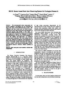
closed-loop security system. FIG. 3 is a waveform diagram of the voltage output of the piezoelectric transducer in FIG. 1. FIG. 4 is a voltage waveform diagram of the voltage at point A in FIG. 1. FIG. 5 is a voltage waveform diagram of the voltage
at point B will decrease to the threshold voltage level of Q1 and Q1 will again turn on (i.e. the circuit will auto matically reset itself after providing an “alarm" indica
on the gate electrode of the JFET transistor in FIG. 1.
Zener diode D1 normally only functions as a forward
tion to the closed loop security system).
biased diode. However, in the case of abnormally large AC voltage pulses from P1 it also conducts in the re security system using the self-powered sensors of the verse (zener) direction thus limiting the maximum input present invention. FIG. 7 is an equivalent electrical schematic of trans 20 voltage to the gate of Q1 to a safe level. FIG. 6 is a block schematic diagram of a closed-loop
Referring now to FIG. 6, there is shown a closed
ducer P1 in FIG. 1.
loop security system which comprises sensors 16, 18 and 20 coupled to JFET transistors Q3, Q4 and Q5
DETAILED DESCRIPTION OF THE INVENTION
which are connected in series with voltage threshold A self-powered sensor 10 includes a piezoelectric 25 detector 22. The aforementioned loop is powered by a current source 24. Connected to the output of voltage transducer PI which includes a piezoelectric element 11 threshold detector 22 is an alarm 26 which may be of sandwiched between plates 13 and 15. The transducer any conventional type. P1 is coupled to a capacitor C1 which is, in turn, con As explained with respect to the sensor network 10 of nected to the gate electrode of JFET transistor Q1. Q1 FIG. 1, the loop switches Q3, Q4 and Q5 are JFET includes a drain electrode D connected to the positive transistors and are therefore normally closed, thus per terminal of a closed loop security system to be de mitting current from current source 24 to flow through scribed below. The source electrode S is connected to the loop at a very low voltage. When one of the the negative terminal of the closed-loop security sys
switches opens, however, the continuity of the loop is
tem. Connected across the source and drain electrodes
of Q1 is a zener diode D2 which serves to protect the 35 broken and the loop voltage rises to some predeter
JFET transister Q1 from an unforseen surge in voltage from the closed loop security system. A resistor R1 is connected between plates 13 and 15 of transducer P1 and a zener diode D1 is connected in parallel with resis tor R1. A second resistor R2 is connected between the 40
mined value determined by the output capability of current source 24. The rise in voltage is detected by the threshold detector 22, and at an appropriate level, alarm 26 is turned on.
The self-powered sensing network of FIG. 1 is con structed using a minimum number of components so as to make the sensor and the associated network as small,
gate electrode G of Q1 and ground.
When stimulated by a physical impact or a shock, the and therefore as unobtrusive, as possible. For example, generator portion “G” of the transducer PI (see FIG. 7) transducer P1 includes a capacitor comprising plates 13 emits a series of transient alternating voltage pulses. The plates 13 and 15 of the piezoelectric transducer P1 form 45 and 15 which act both as a part of the high pass filter (formed by the parallel connection of RI) and as part of a capacitor (refer to FIG. 7) which, together with R1, the voltage doubling network. The second diode in the forms a high pass ?lter so that low frequency phenom voltage doubling network is formed by the gate-source ena are filtered and will not trigger an alarm. Prior to junction in Q1. It is this junction which, acting as a the arrival of a transient AC voltage signal the gate of diode, prevents point B from going positive when a Q! is at zero volts relative to its source terminal and is positive pulse from P1 is present at point A thus charg therefore turned "ON" (i.e. its output appears as a ing C1. Thus, the voltage-doubling network comprises closed switch to a closed loop security system). not only C1 and DI but also the diode formed by the FIG. 3 shows a typical transient AC voltage signal gate-source junction of Q1 and the parallel plates 13 and produced by P1. FIG. 4 shows the resulting voltage 15 of transducer PI. Diode D1 also performs a dual function as described above. This provides an economy both in size of the unit 10 and in the cost of manufactur
waveform at point A in FIG. 1 and FIG. 5 shows the
resulting voltage waveform at point B in FIG. 1. The ?rst positive-going voltage pulse shown in FIG. 3 charges the capacitor portion CPI of PI and C1 in
ing such units.
inverse proportion to their respective values. The fol
lowing negative voltage reverse charges the capacitor in P1 due the forward diode conduction of D1. P1 ca
60
A second embodiment of the invention is shown in FIG. 2. In FIG. 2 a self-powered sensing network 12 comprises a transducer P2 which together with resistor R3 fonns a high pass ?lter. A zener diode D3 is con
pacitor plate 13 is now positive and plate 15 is negative. nected in parallel with R3 and diode D4. Coupled be The next positive-going voltage pulse adds a portion of tween D4 and ground is capacitor C2 and time constant the stored voltage of the capacitor CPI plus the voltage of the positive-going voltage pulse from "G" or P1 to 65 resistor R3. A JFET transistor Q2 is connected between the plus and minus terminals of the network 12 which capacitor C1. This process is repeated with each cycle of the transient AC voltage signal until C1 is charged to approximately twice the peak voltage level of the tran
may be connected to a closed-loop security system of the type shown in FIG. 6. A light-emitting diode D6 is '
5
Re. 33,807
connected between the source and drain electrodes of
Q2 as is protection zener diode D5. An optional feature shown in phantom line in FIG. 2 is an oscillator 14 which may be connected between the positive terminal of network 12 and transducer P2. The operation of the network 12 is similar in many respects to the operation of the device shown in FIG. 1. The positive portion of any transient AC wave from P2 shorts to ground through D3. When the wave goes negative, however, D3 prevents any current ?ow to the
positive plate P2, and P2 charges like a capacitor. Since
6
bling circuit means responsive to the output of said transducer means, said pair of plates forming a
charge storage element of said voltage doubling circuit means, for approximately doubling the peak voltage output of said transducer means to provide said switch actuating signal for a predetermined
period of time; and (b) electronic switch means, said electronic switch means having a semiconductor junction forming a
diode included in said voltage doubling circuit means, said electronic switch means being in a
C2 is connected in parallel with P2, C2 charges as well
normally closed position thereby allowing current
since current is pulled through D2 which negatively charges C2. This brings the potential of the gate of Q2 below the gate threshold voltage, turning Q1 off. Q2
in said closed-loop security system to flow there
then stays off because diode D4 prevents any current ?ow towards the gate of Q2. Thus, this circuit allows a transient to put Q2 in an off position and Q2 will stay off until C2 discharges through R3. If R3 is a very large
through, for opening said closed-loop security sys tem in response to said switch actuating signal. 2. The self-powered sensor of claim 1 wherein said electronic switch means comprises a JFET transistor.
3. The self-powered sensor of claim 1 wherein said electronic switch means comprises a depletion-mode resistor, Q2 may stay turned off for a relatively long 20 MOSFET transistor. period of time. 4. The self-powered sensor of claim 1, further includ When Q2 is turned off, voltage is made available at ing shunt resistor means connected across said plates for the positive terminal of the network 12. Thus, current‘ providing a high pass ?lter for said transducer means. may flow through light-emitting diode D6 providing a 5. The self-powered sensor of claim 1, further includ visual indication identifying the network 12 as the sens
ing network that produced the open-loop condition which is indicated by alarm unit 26. The internal resis
ing alarm means associated with said sensor and cou
pled to said closed-loop security system wherein volt age made available by the opening of said closed loop
tance of D6 is much higher than the drainsource elec security system is used to provide power for said alarm trode connection at Q2 when Q2 is on. Thus when Q2 is means. closed, all current flows between the drain and source 30 6. The sensor of claim 5 wherein said alarm means
of Q2 and no current flows through D6. With Q2 turned off, however, D6 provides a current path between the positive and negative poles of network 12. In the alter
comprises light-emitting diode means connected in par
allel with said electronic switch means. 7. The sensor of claim 5 wherein said self-powered sensor network means includes piezoelectric transducer 35 it emits a sound. The oscillator 14 is powered by voltage means and said alarm means comprises an oscillator from the closed-loop system such as that shown in FIG.
native, oscillator 14 may be used to stimulate P2 so that
6, because when Q2 is turned off, voltage is available at the positive terminal of network 12. The invention has been described using JFET transis tors as loop switches. However, depletion-mode MOS
FETS could also be used. Depletion-mode MOSFETS, however, will require an additional diode between the gate and source terminals when used in the circuit of FIG. 1 because there is no internal junction which can
coupled between said piezoelectric transducer means and a pole of said closed-loop security system for acti
vating said piezoelectric tranducer means so as to cause an audible sound.
8. The sensor of claim 2 wherein said closed-loop security system comprises a positive lead connected to a drain electrode of said JFET transistor and a negative lead connected to a source electrode of said JFET tran
perform the diode function needed in the voltage dou 45 sister and a voltage threshold detector connected be tween said positive and negative leads thereby forming bling network. The circuit of H6. 2, however, requires a closed loop, said closed loop being powered by a no additional diode due to the presence of D4. Other current source. normally closed electronic switches may also be used, 9. The sensor of claim 1 wherein said self-powered the operating characteristics of such switches being well-known in the art. The terms and expressions which have been em
ployed in the foregoing speci?cation are used therein as terms of description and not of limitation, and there is no intention, in the use of such terms and expressions, of
sensor network means comprises a time delay means for maintaining said electronic switch means in an open
position for a predetermined period of time after said switch means has been opened by said switch actuating
signal.
excluding equivalents of the features shown and de 55 10. A self-powered sensor network fora closed loop secu rity system, comprising: scribed or portions thereof, it being recognized that the (a) self-powered sensor means for providing an electrical scope of the invention is de?ned and limited only by the signal upon the detection of a physical condition; claims which follow. (b) timing network means responsive to said electrical What is claimed is: signal for generating a switch-actuating signal, said 1. A self-powered sensor for a closed~loop security switch-actuating signal having a predetermined time system, comprising: period; and (a) self-powered sensor network means for providing (c) electronic switch means coupled to said timing net a switch actuating signal upon the detection of a work meons. said switch means being in a normally physical condition wherein said self'powered sen closed position thereby allowing current in said closed sor network means comprises transducer means, 65 loop security system to flow therethrough. and respon said transducer means having a pair of plates sepa sive to said switch-actuating signal so as to be open rated by a piezoelectric element and having a tran during said predetermined time period. sient alternating current output, and voltage dou
7
Re. 33,807
II. The self-powered sensor network ofclaim 10 wherein
8
15. The self-powered sensor network of claim 10 further including alarm means associated with said closed loop security system wherein voltage made available by the opening of said closed loop security system is used to pro
said self-powered sensor means comprises transducer means for generating a transient AC signal, and wherein said timing network means includes rectifying means for convening said transient AC signal to a DC signal. 5 vide power for said alarm means. J2. The self-powered sensor network ofclaim I] wherein 1 6. The self-powered sensor network ofclaim 15 wherein said timing network means includes an RC timing circuit. said closed loop security system includes a current source 13. The self-powered sensor network ofclaim 12 wherein connected in series with a plurality ofsaid electronic switch said electronic switch means comprises a JFE T transistor. means and a voltage threshold detector connected in paral 14. The self-powered sensor network of claim 12 wherein lel with said current source, said voltage threshold detector said electronic switch means comprises a depletion mode having an output coupled to said alarm means i # l i 8 MOSFET transistor.
20
25
30
35
45
50
55
65
UNITED STATES PATENT AND TRADEMARK OFFICE
CERTIFICATE OF CORRECTION PATENT NO.
:
R133 3 8 0 7
DATED
I
January 28, 1992
INVENTUMS): William E. Abel et al. It is uni?ed that emu appears in the above-identified patent and that said Letters Patent is hereby
correctedasshmbelow: Col. 2
Line
61
After "sensors“ insert ——which may be used to indicate the particular sensor--.
Col. 5
Line
15
Delete "Q1" and insert ——Q2-— in place thereof.
Signed and Sealed this Twenty-ninth Day of June, 1993
Arresr: MICHAEL K. KIRK
AIWSIUIQ Officer
Acting Commission?!‘ of PUH’VHS and Trademarks