1
Replication Routing in DTNs: A Resource Allocation Approach Aruna Balasubramanian Brian Neil Levine Arun Venkataramani Department of Computer Science, University of Massachusetts, Amherst, USA 01003 {arunab, brian, arun}@cs.umass.edu
example, a simple news and information application is better served by maximizing the number of news stories delivered before they are outdated, rather than eventually delivering all stories. In this paper, we formulate the DTN routing problem as a resource allocation problem. The protocol we describe, called RAPID (Resource Allocation Protocol for Intentional DTN) routing, allocates resources to packets to optimize an administratorspecified routing metric. At each transfer opportunity, a RAPID node replicates or allocates bandwidth resource to a set of packets in its buffer, in order to optimize the given routing metric. Packets are delivered through opportunistic replication, until a copy reaches the destination. RAPID makes the allocation decision by first translating the routing metric to a per-packet utility. DTNs are resourceconstrained networks in terms of transfer bandwidth, energy, and storage; allocating resources to replicas without careful attention to available resources can cause more harm than good. Therefore, a RAPID node replicates packets in the order of their marginal utility of replication, i.e., the first packet to I. I NTRODUCTION be replicated is the one that provides the highest increase in Disruption-tolerant networks (DTNs) enable transfer of utility per unit resource used. We show how RAPID can use data when mobile nodes are connected only intermittently. this simple approach to optimize three different routing metrics: Applications of DTNs include large-scale disaster recovery average delay, worst-case delay, and the number of packets networks, sensor networks for ecological monitoring [34], delivered before a deadline. ocean sensor networks [26], [22], vehicular networks [24], RAPID loosely tracks network resources through a control [7], and projects such as TIER [2], Digital Study Hall [14], plane to assimilate a local view of the global network state. To and One Laptop Per Child [1] to benefit developing nations. this end, RAPID uses an in-band control channel to exchange Intermittent connectivity can be a result of mobility, power network state information among nodes using a fraction of management, wireless range, sparsity, or malicious attacks. The the available bandwidth, and uses the additional information inherent uncertainty about network conditions make routing in to significantly improve routing performance. RAPID’s control DTNs a challenging problem. channel builds on insights from previous work. For example, The primary focus of many existing DTN routing protocols Jain et al. [18] suggest that DTN routing protocols that use more is to increase the likelihood of finding a path with extremely knowledge of network conditions perform better, and Burgess et limited information. To discover such a path, a variety of al. [7] show that flooding acknowledgments improves delivery mechanisms are used, including estimating node meeting rates by removing useless packets from the network. We present hardness results to substantiate RAPID’s heuristic probabilities, packet replication, network coding, placement of stationary waypoint stores, and leveraging prior knowledge of approach. We prove that online algorithms without complete mobility patterns. Unfortunately, the burden of finding even one future knowledge and with unlimited computational power, path is so great that existing approaches have only an incidental or computationally limited algorithms with complete future rather than an intentional effect on such routing metrics as knowledge, can be arbitrarily far from optimal. worst-case delivery latency, average delay, or percentage of We have built and deployed RAPID on a vehicular DTN packets delivered. This disconnect between application needs testbed, DieselNet [7], that consists of 40 buses covering and routing protocols hinders deployment of DTN applications. a 150 square-mile area around Amherst, MA. We collected Currently, it is difficult to drive the routing layer of a DTN 58 days of performance traces of the RAPID deployment. To by specifying priorities, deadlines, or cost constraints. For our knowledge, this is the first paper to report on a routing Abstract—Routing protocols for disruption-tolerant networks (DTNs) use a variety of mechanisms, including discovering the meeting probabilities among nodes, packet replication, and network coding. The primary focus of these mechanisms is to increase the likelihood of finding a path with limited information, and so these approaches have only an incidental effect on such routing metrics as maximum or average delivery delay. In this paper, we present RAPID, an intentional DTN routing protocol that can optimize a specific routing metric such as the worstcase delivery delay or the fraction of packets that are delivered within a deadline. The key insight is to treat DTN routing as a resource allocation problem that translates the routing metric into per-packet utilities which determine how packets should be replicated in the system. We evaluate RAPID rigorously through a prototype deployed over a vehicular DTN testbed of 40 buses and simulations based on real traces. To our knowledge, this is the first paper to report on a routing protocol deployed on a real outdoor DTN. Our results suggest that RAPID significantly outperforms existing routing protocols for several metrics. We also show empirically that for small loads, RAPID is within 10% of the optimal performance.
2
protocol deployed on a real outdoor DTN. Similar testbeds have to be [29] that replicating packets can improve performance deployed only flooding as a method of packet propagation [34]. (and security [6]) over just forwarding, but risk degrading We also conduct a simulation-based evaluation using real traces performance when resources are limited. to stress-test and compare various protocols. We show that b) Incidental versus Intentional: Our position is that most the performance results from our trace-driven simulation is existing schemes only have an incidental effect on desired within 1% of the real measurements with 95% confidence. We performance metrics, including commonly evaluated metrics use this simulator to compare RAPID to four existing routing such as average delay or delivery probability. Therefore, the protocols [21], [29], [7] and random routing. We also compare effect of a routing decision on the performance of a given the protocols using synthetic mobility models. resource constrained network scenario is unclear. For example, We evaluate the performance of RAPID for three different several existing DTN routing algorithms [29], [28], [23], [7] routing metrics: average delay, worst-case delay, and the route packets using the number of replicas as the heuristic, but number of packets delivered before a deadline. All experiments the effect of replication varies with different routing metrics. include the cost of RAPID’s control channel. Our experiments Spray and Wait [29] routes to reduce delay metric, but it does using trace-driven and synthetic mobility scenarios show that not take into account bandwidth or storage constraints. In RAPID significantly outperforms the four routing protocols. contrast, routing in RAPID is intentional with respect to a given For example, in trace-driven experiments under moderate-to- performance metric. RAPID explicitly calculates the effect of high loads, RAPID outperforms the second-best protocol by replication on the routing metric while accounting for resource about 20% for all three metrics, while also delivering 15% constraints. more packets for the first two metrics. With a priori mobility c) Resource Constraints: RAPID also differs from most information and moderate-to-high loads, RAPID outperforms previous work in its assumptions regarding resource constraints, random replication by about 50% for high packet loads. We also routing policy, and mobility patterns. Table I shows a taxonomy compare RAPID to an optimal protocol and show empirically of many existing DTN routing protocols based on assumptions that RAPID performs within 10% of optimal for low loads. about bandwidth available during transfer opportunities and the storage carried by nodes; both are either finite or unlimited. For each work, we state in parentheses the mobility model used. II. R ELATED WORK RAPID is a replication-based algorithm that assumes constraints a) Replication versus Forwarding: We classify related on both storage and bandwidth (P5) — the most challenging existing DTN routing protocols as those that replicate packets and most practical problem space. and those that forward only a single copy. Epidemic routing P1 and P2 are important to examine for valuable insights protocols replicate packets at transfer opportunities hoping to that theoretical tractability yields but are impractical for real find a path to a destination. However, naive flooding wastes DTNs with limited resources. Many studies [21], [13], [8], resources and can severely degrade performance. Proposed [28] analyze the case where storage at nodes is limited, but protocols attempt to limit replication or otherwise clear useless bandwidth is unlimited (P3). However, we find this scenario to packets in various ways: (i) using historic meeting informa- be uncommon. Bandwidth is likely to be constrained for most tion [13], [8], [7], [21]; (ii) removing useless packets using typical DTN scenarios. Specifically, in mobile and vehicular acknowledgments of delivered data [7]; (iii) using probabilistic DTNs, transfer opportunities are typically short-lived [16], [7]. mobility information to infer delivery [28]; (iv) replicating We were unable to find other protocols in P5 except packets with a small probability [33]; (v) using network MaxProp [7] that assume limited storage and bandwidth. coding [32] and coding with redundancy [17]; and (vi) bounding However, it is unclear how to optimize a specific routing metric the number of replicas of a packet [29], [28], [23]. using MaxProp, so we categorize it as an incidental routing In contrast, forwarding routing protocols maintain at most protocol. Our experiments indicate that RAPID outperforms one copy of a packet in the network [18], [19], [31]. Jain et MaxProp for each metric that we evaluate. al. [18] propose a forwarding algorithm to minimize the average Some theoretical works [35], [30], [28], [5] derive closeddelay of packet delivery using oracles with varying degrees of form expressions for average delay and number of replicas in future knowledge. Our deployment experience suggests that, the system as a function of the number of nodes and mobility even for a scheduled bus service, implementing the simplest patterns. Although these analyses contributed to important oracle is difficult; connection opportunities are affected by insights in the design of RAPID, their assumptions about many factors in practice including weather, radio interference, mobility patterns or unlimited resources were, in our experience, and system failure. Furthermore, we present formal hardness too restrictive to be applicable to practical settings. and empirical results to quantify the impact of not having complete knowledge. III. T HE RAPID P ROTOCOL Jones et al. [19] propose a link-state protocol based on epidemic propagation to disseminate global knowledge, but A. System model use a single path to forward a packet. Shah et al. [27] and We model a DTN as a set of mobile nodes. Two nodes Spyropoulos et al. [31] present an analytical framework for the transfer data packets to each other when within communication forwarding-only case assuming a grid-based mobility model. range. During a transfer, the sender replicates packets while They subsequently extend the model and propose a replication- retaining a copy. A node can deliver packets to a destination based protocol, Spray and Wait [29]. The consensus appears node directly or via intermediate nodes, but packets may not
3
Problem P1
Storage Unlimited
Bandwidth Unlimited
Routing Replication
P2 P3
Unlimited Finite
Unlimited Unlimited
Forwarding Replication
P4 P5
Finite Finite
Finite Finite
Forwarding Replication
Previous work (and mobility) Epidemic [23], Spray and Wait [29]: Constraint in the form of channel contention (Grid-based synthetic) Modified Djikstra’s et al. [18] (simple graph), MobySpace [20] (Powerlaw) Davis et al. [13] (Simple partitioning synthetic), SWIM [28] (Exponential), MV [8] (Community-based synthetic), Prophet [21] (Community-based synthetic) Jones et al. [19] (AP traces), Jain et al. [18] (Synthetic DTN topology) This paper (Vehicular DTN traces, exponential, and power law meeting probabilities, testbed deployment), MaxProp [7] (Vehicular DTN traces)
TABLE I A CLASSIFICATION OF SOME RELATED WORK INTO DTN ROUTING SCENARIOS
D(i)
Packet i’s expected delay = T (i) + A(i)
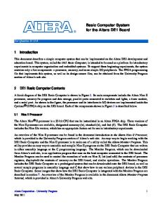
be fragmented. There is limited storage and transfer bandwidth T (i) Time since creation of i available to nodes. Destination nodes are assumed to have a(i) Random variable that determines the remaining time to deliver i sufficient capacity to store delivered packets, so only storage for A(i) Expected remaining time = E[a(i)] in-transit data is limited. Node meetings are assumed to be shortMXZ Random variable that determines inter-meeting time between lived. The nodes are assumed to have sufficient computational nodes X and Z capabilities as well as enough resources to maintain state TABLE II information. L IST OF COMMONLY USED VARIABLES . Formally, a DTN consists of a node meeting schedule and a workload. The node meeting schedule is a directed multigraph G = (V, E), where V and E represent the set of nodes and edges, respectively. Each directed edge e between two with the highest value of δU /s among packets in its buffer; i i nodes represents a meeting between them, and it is annotated in other words, the packet with the highest marginal utility. with a tuple (te , se ), where t is the time and s is the size In general, Ui is defined as the expected contribution of i of the transfer opportunity. The workload is a set of packets to the given routing metric. For example, the metric minimize P = {(u1 , v1 , s1 , t1 ), (u2 , v2 , s2 , t2 ), . . .}, where the ith tuple average delay is measured by summing the delay of packets. represents the source, destination, size, and time of creation Accordingly, the utility of a packet is its expected delay. Thus, (at the source), respectively, of packet i. The goal of a DTN RAPID is a heuristic based on locally optimizing marginal routing algorithm is to deliver all packets using a feasible utility, i.e., the expected increase in utility per unit resource schedule of packet transfers, where feasible means that the used. total size of packets transfered during each opportunity is less Using the marginal utility heuristic has some desirable than the size of the opportunity, always respecting storage properties. The marginal utility of replicating a packet to a constraints. node is low when (i) the packet has many replicas, or (ii) the In comparison to Jain et al.[18] who model link properties node is a poor choice with respect to the routing metric, or as continuous functions of time, our model assumes discrete (iii) the resources used do not justify the benefit. For example, short-lived transfers; this makes the problem analytically more if nodes meet each other uniformly, then a packet i with 6 tractable and characterizes many practical DTNs well. replicas has lower marginal utility of replication compared to a packet j with just 2 replicas. On the other hand, if the peer is unlikely to meet j’s destination for a long time, then i may B. RAPID design take priority over j. RAPID models DTN routing as a utility-driven resource RAPID has three core components: a selection algorithm, allocation problem. A packet is routed by replicating it until a an inference algorithm, and a control channel. The selection copy reaches the destination. The key question is: given limited algorithm is used to determine which packets to replicate bandwidth, how should packets be replicated in the network at a transfer opportunity given their utilities. The inference so as to optimize a specified routing metric? RAPID derives a algorithm is used to estimate the utility of a packet given the per-packet utility function from the routing metric. At a transfer routing metric. The control channel propagates the necessary opportunity, it replicates a packet that locally results in the metadata required by the inference algorithm. highest increase in utility. Consider a routing metric such as minimize average delay of packets, the running example used in this section. The C. The selection algorithm corresponding utility Ui of packet i is the negative of the The RAPID protocol executes when two nodes are within expected delay to deliver i, i.e., the time i has already spent radio range and have discovered one another. The protocol is in the system plus the additional expected delay before i is symmetric; without loss of generality, we describe how node delivered. Let δUi denote the increase in Ui by replicating i X determines which packets to transfer to node Y (refer to and si denote the size of i. Then, RAPID replicates the packet the box marked P ROTOCOL RAPID).
4
P ROTOCOL RAPID(X, Y ): 1) Initialization: Obtain metadata from Y about packets in its buffer as well as metadata it collected over past meetings (detailed in Section IV-B). 2) Direct delivery: Deliver packets destined to Y in decreasing order of creation times. 3) Replication: For each packet i in node X’s buffer a) If i is already in Y ’s buffer (as determined from the metadata), ignore i. b) Estimate marginal utility, δUi /si , of replicating i to Y . c) Replicate packets in decreasing order of marginal utility. 4) Termination: End transfer when out of radio range or all packets replicated.
the routing algorithm to be work conserving, RAPID computes utility for the packet whose delay is currently the maximum; i.e., once a packet with maximum delay is evaluated for replication, the utility of the remaining packets is recalculated using Eq. 3. IV. E STIMATING DELIVERY DELAY
How does a RAPID node estimate expected delay in Eqs. 1 and 3, or the probability of packet delivery within a deadline in Eq. 2? The expected delivery delay is the minimum expected time until any node with the replica of the packet delivers the packet; so a node needs to know which other nodes possess replicas of the packet and when they expect to meet the destination. To estimate expected delay we assume that each node with the copy of the packet delivers the packet directly to the destination, ignoring the effect of further replications. This assumption simplifies the expected delay estimation, RAPID also adapts to storage restrictions for in-transit data. and we make this assumption only for networks with dense If a node exhausts all available storage, packets with the node meetings, were every node meets every other node. In lowest utility are deleted first as they contribute least to overall Section IV-A2, we describe a modification to this assumption performance. However, a source never deletes its own packet for networks with sparse node meetings. Estimating expected delay is nontrivial even with an accurate global snapshot of unless it receives an acknowledgment for the packet. system state. For ease of exposition, we first present RAPID’s estimation algorithm as if we had knowledge of the global D. Inference algorithm system state, and then we present a practical distributed Next, we describe how P ROTOCOL RAPID can support implementation. specific metrics using an algorithm to infer utilities. Table II defines the relevant variables. 1) Metric 1: Minimizing average delay: To minimize the A. Algorithm Estimate Delay average delay of packets in the network we define the utility A RAPID node uses the algorithm E STIMATE D ELAY to of a packet as estimate the delay of a packet in its buffer. E STIMATE D ELAY Ui = −D(i) (1) works as follows (refer to box marked A LGORITHM E STI MATE D ELAY): In Step 1, each node X maintains a separate since the packet’s expected delay is its contribution to the queue of packets Q destined to a node Z sorted in decreasing performance metric. RAPID attempts to greedily replicate the order of creation times; this is the order in which the packets packet whose replication reduces the delay by the most among will be delivered when X meets Z in PROTOCOL RAPID. all packets in its buffer. In Step 2 of E STIMATE D ELAY, X computes the delivery 2) Metric 2: Minimizing missed deadlines: To minimize delay distribution of packet i if delivered directly by X. In the number of packets that miss their deadlines, the utility is Step 3, X computes the minimum across all replicas of the defined as the probability that the packet will be delivered corresponding delivery delay distributions; we note that the within its deadline: delivery time of i is the time until the first node delivers � P (a(i) < L(i) − T (i)), L(i) > T (i) Ui = (2) the packet. E STIMATE D ELAY assumes that the meeting time 0, otherwise distribution is the same as the inter-meeting time distribution. The Assumption 2 in E STIMATE D ELAY is a simplifying inwhere L(i) is the packet life-time. A packet that has missed dependence assumption that does not hold in general. Consider its deadline can no longer improve performance and is thus Figure 2(a), an example showing the positions of packet replicas assigned a value of 0. The marginal utility is the improvement in the queues of different nodes. All packets have a common in the probability that the packet will be delivered within its destination Z and each queue is sorted by T (i). Assume that deadline. the transfer opportunities and packets are of unit-size. 3) Metric 3: Minimizing maximum delay: To minimize In Figure 2(a), packet b may be delivered in two ways: (i) the maximum delay of packets in the network, we define the if W meets Z; (ii) one of X and Y meets Z and then one utility Ui as � of X and Y meet Z again. These delay dependencies can be −D(i), D(i) ≥ D(j) ∀j ∈ S Ui = (3) represented using a dependency graph as illustrated in Fig 2(b); 0, otherwise packets with the same letter and different indices are replicas. where S denotes the set of all packets in X’s buffer. Thus, Ui is A vertex corresponds to a packet replica. An edge from one the negative expected delay if i is a packet with the maximum node to another indicates a dependency between the delays expected delay among all packets held by Y . So, replication of the corresponding packets. Recall that MXY is the random is useful only for the packet whose delay is maximum. For variable that represents the meeting time between X and Y .
5
A LGORITHM E STIMATE D ELAY: Node X storing a set of packets Q to destination Z performs the following steps to estimate the time until packet i ∈ Q is delivered 1) X sorts all packets i ∈ Q in the descending order of T (i), time since i is created. a) Let b(i) be the sum size of packets that precede packet i in the sorted list of X. Figure 1 illustrates a sorted buffer containing packet i. b) Let B be the expected transfer opportunity in bytes between X and Z. (For readability, we drop subscript X since we are only talking about one node; in general b(i) and B are functions of the node). Node X locally computes B as a moving average of past transfers between X and Z. 2) Assumption 1: Suppose only X delivers packets to Z with no further replication. Let aX (i) be the delay distribution of X delivering the packet. Under our assumption, X requires db(i)/Be meetings with Z to deliver i. Let M be a distribution that models the intermeeting times between nodes, and let MX,Z be the random variable that represents the time taken for X and Z to meet. We transform MX,Z to random 0 that represents the time until X and variable MX,Z Z meet db(i)/Be times. Then, by definition
B bytes
Sorted list of packets destined to Z
(Average transfer size)
i
b(i) bytes (Sum of packets before i)
Position of packet i in a queue of packets destined to Z.
Fig. 1.
b
a
a
d
b
b
d
c
Node X
Node Y
Node W
b1
a1
d1
b2 d2
Node W (a) Packet destined to Z buffered at different nodes
Node X
a2 b3 c1 Node Y
(b) Delay dependancies between packets destined to node Z
Fig. 2. Delay dependencies between packets destined to Z buffered in different nodes.
is of theoretical interest, it cannot be implemented in practice because DAG DELAY assumes that — (i) the transfer opportunity size is exactly equal to the size of a packet.This assumption is fundamental for the design of DAG DELAYand (ii) nodes have a global view of the system. In general, ignoring non-vertical edges can arbitrarily inflate delay estimates for some pathological cases (detailed in a Technical report [3]). However, we find that E STIMATE D ELAY 0 aX (i) = MX,Z (4) works well in practice, and is simple and does not require a global view of the system. 3) Assumption 2: Suppose the k random variables 1) Estimating delays when transfer opportunities are exay (i), y ∈ [1, k] were independent, where k is the ponentially distributed: We walk through the distributed number of replicas of i. implementation of E STIMATE D ELAY for a scenario where the The probability of delivering i within time t is the inter-meeting time between nodes is exponentially distributed. minimum of the k random variables ay (i), y ∈ [1, k]. Assume that the mean meeting time between nodes is λ1 . In the This probability is: absence of bandwidth restrictions, the expected delivery delay k Y when there are k replicas is the mean meeting time divided P(a(i) < t) = 1 − (1 − P(ay (i) < t) (5) 1 by k, i.e., P(a(i) < t) = 1 − e−kλt and A(i) = kλ . (Note that y=1 the minimum of k i.i.d. exponentials is also an exponential a) Accordingly: with mean k1 of the mean of the i.i.d exponentials [9].) A(i) = E[a(i)] (6) When transfer opportunities are limited, the expected delay depends on the packet’s position in the nodes’ buffers. In Step 2 E STIMATE D ELAY ignores all the non-vertical dependencies. of E STIMATE D ELAY, the node estimates the number of times it needs to meet the destination to deliver a packet as a function For example, it estimates b’s delivery time distribution as of db(i)/Be. According to our exponential meeting time min(MW Z , MXZ + MXZ , MY Z + MY Z ), assumption, the time for some node X to meet the destination db(i)/Be times is described by a gamma distribution with whereas the distribution is actually mean λ1 · db(i)/Be. If packet i is replicated at k nodes, Step 3 computes the min(MW Z , min(MXZ , MY Z ) + min(MXZ , MY Z )). delay distribution a(i) as the minimum of k gamma variables. Estimating delays without ignoring the non-vertical de- We do not know of a closed form expression for the minimum pendancies is challenging. Using a simplifying assumption of gamma variables. Instead, if we assume that the time taken that the transfer opportunities and packets are unit-sized, for a node to meet the destination b(i)/B times is exponential we design algorithm DAG DELAY(described in a Technical with the same mean λ1 · db(i)/Be. We can then estimate a(i) report citerapid-tr), that estimates the expected delay by taking as the minimum of k exponentials. into account non-vertical dependancies. Although DAG DELAY Let n1 (i), n2 (i), . . . , nk (i) be the number of times each of
6
the k nodes respectively needs to meet the destination to deliver i directly. Then A(i) is computed as:
B. Control channel
Previous studies [18] have shown that as nodes have the benefit of more information about global system state using (7) oracles, they can make significantly better routing decisions. P(a(i) < t) = 1 − e 1 We extend this idea to practical DTNs where no oracle is A(i) = λ (8) λ λ available. RAPID nodes gather knowledge about the global n1 (i) + n2 (i) + . . . + nk (i) system state by disseminating metadata using a fraction of the When the meeting time distributions between nodes are transfer opportunity. RAPID uses an in-band control channel to exchange acknowlnon-uniform, say with means λ11 , λ12 . . . λ1k respectively, then λk −1 λ2 λ1 edgments for delivered packets as well as metadata about every A(i) = ( n1 (i) + n2 (i) + . . . + nk (i) ) . packet learnt from past exchanges. For each encountered packet 2) Estimating delays when transfer opportunity distribution i, RAPID maintains a list of nodes that carry the replica of i, and is unknown: To implement RAPID on the DieselNet testbed, for each replica, an estimated time for direct delivery. Metadata we adapt Eq. 8 to scenarios where the transfer opportunities are for delivered packets is deleted when an ack is received. not exponentially distributed. First, to estimate mean inter-node For efficiency, a RAPID node maintains the time of last meeting times in the DieselNet testbed, every node tabulates the metadata exchange with its peers. The node only sends average time to meet every other node based on past meeting information about packets whose information changed since times. Nodes exchange this table as part of metadata exchanges the last exchange, which reduces the size of the exchange (Step 1 in P ROTOCOL RAPID). A node combines the metadata considerably. A RAPID node sends the following information into a meeting-time adjacency matrix and the information is on encountering a peer: (i) Average size of past transfer updated after each transfer opportunity. The matrix contains opportunities; (ii) Expected meeting times with nodes; (iii) the expected time for two nodes to meet directly, calculated Acks; (iv) For each of its own packets, the updated delivery as the average of past meetings. delay estimate based on current buffer state; (v) Delivery delay Node X estimates E(MXZ ), the expected time to meet of other packets if modified since last exchange. Z, using the meeting-time matrix. E(MXZ ) is estimated as When using the control channel, nodes have only an imperthe expected time taken for X to meet Z in at most h hops. fect view of the system. The propagated information may be (Unlike uniform exponential mobility models, some nodes in stale due to changes in number of replicas, changes in delivery the trace never meet directly.) For example, if X meets Z via delays, or if the packet is delivered but acknowledgments have an intermediary Y , the expected meeting time is the expected not propagated. Nevertheless, our experiments confirm that (i) time for X to meet Y and then Y to meet Z in 2 hops. In our this inaccurate information is sufficient for RAPID to achieve implementation we restrict h = 3. When two nodes never meet, significant performance gains over existing protocols and (ii) even via three intermediate nodes, we set the expected interthe overhead of metadata itself is not significant. meeting time to infinity. Several DTN routing protocols [7], [21], [8] use similar techniques to estimate meeting probability V. T HE CASE FOR A HEURISTIC APPROACH among peers. Any DTN routing algorithm has to deal with two uncertainRAPID estimates expected meeting times by taking into account transitive meetings. However, our delivery estimation ties regarding the future: unpredictable meeting schedule and (described in E STIMATE D ELAY) assumes that nodes do unpredictable workload. RAPID is a local algorithm that routes not make additional replicas. This disconnect is because, in packets based on the marginal utility heuristic in the face of DieselNet, only few buses meet directly, and the pair-wise these uncertainties. In this section, we show two fundamental meeting times between several bus pairs is infinity. We take reasons that make the case for a heuristic approach to DTN into account transitive meetings when two buses do not meet routing. First, we prove that computing optimal solutions is hard even with complete knowledge about the environment. Second, directly, to increase the number of potential forwarders. Let replicas of packet i destined to Z reside at nodes we prove that the presence of even one of the two uncertainties X1 , . . . , Xk . Since we do not know the meeting time dis- rule out provably efficient online routing algorithms. tributions, we simply assume they are exponentially distributed. Then from Eq. 8, the expected delay to deliver i is A. Computational Hardness of the DTN Routing Problem −( n λ(i) + n λ(i) +...+ n λ(i) )t 1 2 k
k X
1
j=1
E(MXj Z ) · nj (i)
A(i) = [
−1
]
(9)
We use an exponential distribution because bus meeting times in the testbed are difficult to model. Buses change routes several times in one day, the inter-bus meeting distribution is noisy, and we found them hard to model even using mixture models. Approximating meeting times as exponentially distributed makes delay estimates easy to compute and performs well in practice.
T HEOREM 2: Given complete knowledge of node meetings and the packet workload a priori, computing a routing schedule that is optimal with respect to the number of packets delivered is NP-hard and has a lower bound of Ω(n1/2−� ) on the approximation ratio. Proof: Consider a DTN routing problem with n nodes that have complete knowledge of node meetings and workload a priori. The input to the DTN problem is the set of nodes 1, . . . , n; a series of transfer opportunities {(u1 , v1 , s1 , t1 ), (u2 , v2 , s2 , t2 ), . . .} such that ui , vi ∈ [1, n], si is the size of the transfer opportunity, and ti is the time
7
of meeting; and a packet workload {p1 , p2 , . . . ps }, where pi = (u0i , vi0 , s0i , t0i ), where u0 , v 0 ∈ [1, n] are the source and destination, s0 the size, and t0 the time of creation of the packet, respectively. The goal of a DTN routing algorithm is to compute a feasible schedule of packet transfers, where feasible means that the total size of transferred packets in any transfer opportunity is less than the size of the transfer opportunity. The decision version On,k of this problem is: Given a DTN with n nodes such that nodes have complete knowledge of transfer opportunities and the packet workload, is there a feasible schedule that delivers at least k packets? L EMMA 1: O(n, k) is NP-hard. Proof: We show that O(n, k) is a NP-hard problem using a polynomial-time reduction from the edge-disjoint path (EDP) problem for a directed acyclic graph (DAG) to O(n, k). The EDP problem for a DAG is known to be NP-hard [11]. The decision version of EDP problem is: Given a DAG G = (V, E), where |V | = n, E ∈ V × V : ei = (ui , vi ) ∈ E, if ei is incident on ui and vi and direction is from ui to vi . If given source-destination pairs {(s1 , t1 ), (s2 , t2 )...(ss , ts )}, do a set of edge-disjoint paths {c1 , c2 ...ck } exist, such that ci is a path between si and ti , where 1 ≤ i ≤ k. Given an instance of the EDP problem, we generate a DTN problem O(n, k) as follows: As the first step, we topologically order the edges in G, which is possible given G is a DAG. The topological sorting can be performed in polynomial-time. Next, we label edges using natural numbers with any function l : E → such that if ei = (ui , uj ) and ej = (uj , uk ), then l(ei ) < l(ej ). There are many ways to define such a function l. One algorithm is:
paths in G, at least k packets can be delivered using the set of transfer opportunities represented by each path. Using the above polynomial-time reduction, we show that a solution to EDP exists if and only if a solution to O(n, k) exists. Thus, O(n, k) is NP-hard. C OROLLARY 1: The DTN routing problem has a lower bound of Ω(n1/2−� ) on the approximation ratio. Proof: The reduction given above is a true reduction in the following sense: each successfully delivered DTN packet corresponds to an edge-disjoint path and vice-versa. Thus, the optimal solution for one exactly corresponds to an optimal solution for the other. Therefore, this reduction is an L-reduction [25]. Consequently, the lower bound Ω(n1/2−� ) known for the hardness of approximating the EDP problem [15] holds for the DTN routing problem as well. Hence, Theorem 2. The hardness results naturally extend to the average delay metric for both the online as well as computationally limited algorithms. B. Competitive Hardness of Online DTN Routing Intermediate
u1 P = {p1 , p2 ...pn } pi destined to vi
Destination
v1
u2
N
un−1 1) label = 0 2) For each vertex v in the decreasing order of the topologun vn ical sort, a) Choose unlabeled edge e = (v, x) : x ∈ V , Fig. 3. DTN node meetings for Theorem V-B. Solid arrows represent node b) label = label + 1 meetings known a priori to the online algorithm while dotted arrows represent c) Label e; l(e) = label. meetings revealed subsequently by an offline adversary. Since vertices are topologically sorted, if ei = (ui , uj ) then ui < uj . Since the algorithm labels all edges with source ui Let ALG be any deterministic online DTN routing algorithm before it labels edges with source uj , if ej = (uj , uk ), then with unlimited computational power. l(ei ) < l(ej ). Given a G, we define a DTN routing problem by mapping T HEOREM 1(a). If ALG has complete knowledge of the V to the nodes (1, .., n) in the DTN. The edge (e = {u, v} : workload, but not of the schedule of node meetings, then ALG u, v ∈ V ) is mapped to the transfer opportunity (u, v, 1, l(e)), is Ω(n)-competitive with an offline adversary with respect to assuming transfer opportunities are unit-sized. Source and the fraction of packets delivered, where n is the number of destination pairs {(s1 , t1 ), (s2 , t2 ), . . . , (sm , tm )} are mapped packets in the workload. Proof: We prove the theorem by constructing an offline to packets {p1 , p2 , . . . , pm }, where pi = (si , ti , 1, 0). In other words, packet p is created between the corresponding source- adversary, ADV, that incrementally generates a node meeting destination pair at time 0 and with unit size. A path in graph schedule after observing the actions of ALG at each step. We G is a valid route in the DTN because the edges on a path show how ADV can construct a node meeting schedule such are transformed to transfer opportunities of increasing time that ADV can deliver all packets while ALG, without prior steps. Moreover, a transfer opportunity can be used to send knowledge of node meetings, can deliver at most 1 packet. Consider a DTN as illustrated in Fig. 3, where no more than one packet because all opportunities are unitsized. If we solve the DTN routing problem of delivering k P = {p1 , p2 , . . . , pn } denotes a set of unit-sized packets; packets, then there exists k edge-disjoint paths in graph G, or U = {u1 , u2 , . . . , un } denotes a set of intermediate nodes; in other words we can solve the EDP problem. Similarly, if and V = {v1 , v2 , . . . , vn } denotes a set of nodes to which the EDP problem has a solution consisting of k edge-disjoint the packets are respectively destined, i.e. pi is destined to vi
8
for all i ∈ [1, n]. The following procedure describes ADV’s actions given ALG as input. P ROCEDURE FOR ADV: • Step 1: ADV generates a set of node meetings involving unit-size transfer opportunities at time t = 0 between A and each of the intermediate nodes u1 , . . . , un respectively (refer to Figure 3). • Step 2: At time t1 > 0, ADV observes the set of transfers X made by ALG. Without loss of generality, X : P → U is represented as a (one-to-many) mapping where X(pi ) is the set of intermediate nodes (u1 , u2 · · · un ) to which ALG replicates packet pi . • Step 3: ADV generates the next set of node meetings (u1 , Y (u1 )), (u2 , Y (u2 )), . . . , (un , Y (un )) at time t1 , where Y : U → V is a bijective mapping from the set of intermediate nodes to the destination nodes v1 , v2 , · · · vn . ADV uses the following procedure to generate the mapping Y given X in Step 3. P ROCEDURE G ENERATE Y(X): 1) Initialize Y (pi ) to null for all i ∈ [1, n]; 2) for each i ∈ [1, n] do 3) if ∃j : uj ∈ / X(pi ) and Y (uj ) = null, then 4) Map Y (uj ) → vi for the smallest such j; 5) else 6) Pick a j: Y (uj ) = null, and map Y (uj ) → vi 7) endif L EMMA 2: ADV executes Line 6 in G ENERATE Y(X) at most once. Proof: We first note that the procedure is well defined at Line 6: each iteration of the main loop map exactly one node in U to a node in V , therefore a suitable j such that Y (uj ) = null exists. Suppose ADV first executes Line 6 in the m’th iteration. By inspection of the code, the condition in Line 3 is false, therefore each intermediate node uk , k ∈ [1, n], either belongs to X(pi ) or is mapped to some destination node Y (uk ) 6= null. Since each of the m − 1 previous iterations must have executed Line 4 by assumption, exactly m − 1 nodes in U have been mapped to nodes in V . Therefore, each of the remaining n − m + 1 unmapped nodes must belong to X(pi ) in order to falsify Line 3. Line 6 maps one of these to vi leaving n − m unmapped nodes. None of these n − m nodes is contained in X(pk ) for k ∈ [m + 1, . . . , n]. Thus, in each of the subsequent n − m iterations, the condition in Line 3 evaluates to true. L EMMA 3: The schedule of node meetings created by Y allows ALG to deliver at most one packet to its destination. Proof: For ALG to deliver any packet pi successfully to its destination vi , it must be the case that some node in X(pi ) maps to vi . Such a mapping could not have occurred in Line 3 by inspection of the code, so it must have occurred in Line 6. By Lemma 2, Line 6 is executed exactly once, so ALG can deliver at most one packet. L EMMA 4: The schedule of node meetings created by Y allows ADV to deliver all packets to their respective destinations.
Proof: We first note that, by inspection of the code, Y is a bijective mapping: Line 4 and 6 map an unmapped node in U to vi in iteration m and there are n such iterations. So, ADV can route pi by sending it Y −1 (vi ) and subsequently to vi . Theorem 1(a) follows directly from Lemmas 3 and 4. C OROLLARY 2: ALG can be arbitrarily far from ADV with respect to average delivery delay. Proof: The average delivery delay is unbounded for ALG because of undelivered packets in the construction above while it is finite for ADV. If we assume that that ALG can eventually deliver all packets after a long time T (say, because all nodes connect to a well-connected wired network at the end of the day), then ALG is Ω(T )-competitive with respect to average delivery delay using the same construction as above. We remark that it is unnecessary in the construction above for the two sets of n node meetings to occur simultaneously at t = 0 and t = t1 , respectively. The construction can be easily modified to not involve any concurrent node meetings. T HEOREM 1(b). If ALG has complete knowledge of the meeting schedule, but not of the packet workload, then ALG can deliver at most a third of the packets delivered by an optimal offline adversary. Proof: We prove the theorem by constructing a procedure for ADV to incrementally generate a packet workload by observing ALG’s transfers at each step. As before, we only need unit-sized transfer opportunities and packets for the construction. Consider the basic DTN “gadget” shown in Fig. 4(a) involving just six node meetings. The node meetings are known in advance and occur at times T1 and T2 > T1 respectively. The workload consists of just two packets P = {p1 , p2 } destined to v1 and v2 , respectively. L EMMA 5: ADV can use the basic gadget to force ALG to drop half the packets while itself delivering all packets. Proof: The procedure for ADV is as follows. If ALG transfers p1 to v10 and p2 to v20 , then ADV generates two more packets: p02 at v10 destined to v2 and p01 at v20 destined to v1 . ALG is forced to drop one of the two packets at both v10 and v20 . ADV can deliver all four packets by transferring p1 and p2 to v20 and v10 respectively at time T1 , which is the exact opposite of ALG’s choice. If ALG instead chooses to transfer p1 to v20 and p2 to v10 , ADV chooses the opposite strategy. If ALG chooses to replicate one of the two packets in both transfer opportunities at time T1 while dropping the other packet, ADV simply deliver both packets. Hence the lemma. Next, we extend the basic gadget to show that ALG can deliver at most a third of the packets while ADV delivers all packets. The corresponding construction is shown in Figure 4(b). The construction used by ADV composes the basic gadget repeatedly for a depth of 2. In this construction, ADV can force ALG to drop 2/5th of the packet while ADV delivers all packets. We provide the formal argument in a technical
9
T1 Basic Gadget
v1!
Once a bus is found, a connection is created to the remote AP. (It is likely that the remote bus then creates a connection to the discovered AP, which our software merges into one connection event.) The connection lasts until the radios are out of range. Burgess et al. [7] describes the DieselNet testbed in more detail.
v1
p1 , p2 A
v2 v2! T1
T2 (a) The basic gadget forces ALG to drop half the packets.
p3
v1!!
v1
p!1
S
p!1
v3!!
v3
v2!!
v2
v1!
p1 , p2
v2! p!2 p!2
R
p4 T1
T2
T3
v4!! T4
v4 T5
(b) ADV can use a gadget of depth 2 to force ALG to deliver at most 2/5'th of the packets
Fig. 4. DTN construction for Theorem V-B. Solid arrows represent node meetings known a priori to ALG while vertical dotted arrows represent packets created by ADV at the corresponding node.
report [3] in the interest of space. Similarly, by creating a gadget of depth 3, we can show that ADV can force ALG to deliver at most 4/11’th of the packets. Effectively, each new basic gadget introduces 3 more packets and forces ALG to drop 2 more packets. In particular, with a gadget of depth i, ADV can limit ALG’s delivery rate to i/(3i − 1). Thus, by composing a sufficiently large number of basic gadgets, ADV can limit the delivery rate of ALG to a value close to 1/3. Hence, Theorem 1(b). VI. I MPLEMENTATION ON A VEHICULAR DTN TESTBED We implemented and deployed RAPID on our vehicular DTN testbed, DieselNet [7] (http://prisms.cs.umass.edu/dome), consisting of 40 buses, of which a subset is on the road each day. The routing protocol implementation is a first step towards deploying realistic DTN applications on the testbed. In addition, the deployment allows us to study the effect of certain events that are not perfectly modeled in the simulation of our routing protocol. These events include delays caused by computation, wireless channel interference, and operating system delays. Each bus in DieselNet carries a small-form desktop computer, 40 GB of storage, and a GPS device. The buses operate a 802.11b radio that scans for other buses 10 times a second and an 802.11b access point (AP) that accepts incoming connections.
A. Deployment Buses in DieselNet send messages using PROTOCOL RAPID in Section III, computing the metadata as described in Section IV-B. We generated packets of size 1 KB periodically on each bus with an exponential inter-arrival time. The destinations of the packets included only buses that were scheduled to be on the road, which avoided creation of many packets that could never be delivered. We did not provide the buses information about the location or route of other buses on the road. We set the default packet generation rate to 4 packets per hour generated by each bus for every other bus on the road; since the number of buses on the road at any time varies, this is the simplest way to express load. For example, when 20 buses are on the road, the default rate is 1,520 packets per hour. During the experiments, the buses logged packet generation, packet delivery, delivery delay, meta-data size, and the total size of the transfer opportunity. Buses transfered random data after all routing was complete in order to measure the capacity and duration of each transfer opportunity. The logs were periodically uploaded to a central server using open Internet APs found on the road. B. Performance of deployed RAPID We measured the routing performance of RAPID on the buses from Feb 6, 2007 until May 14, 20071 . The measurements are tabulated in Table III. We exclude holidays and weekends since almost no buses were on the road, leaving 58 days of experiments. RAPID delivered 88% of packets with an average delivery delay of about 91 minutes. We also note that overhead due to meta-data accounts for less than 0.2% of the total available bandwidth and less than 1.7% of the data transmitted. C. Validating trace-driven simulator In the next section, we evaluate RAPID using a trace-driven simulator. The simulator takes as input a schedule of node meetings, the bandwidth available at each meeting, and a routing algorithm. We validated our simulator by comparing simulation results against the 58-days of measurements from the deployment. In the simulator, we generate packets under the same assumptions as the deployment, using the same parameters for exponentially distributed inter-arrival times. Figure 5 shows the average delay characteristics of the real system and the simulator. Delays measured using the simulator were averaged over the 30 runs and the error-bars show a 95% confidence interval. From those results and further analysis, we find with 95% confidence that the simulator results are within 1% of the implementation measurement of average delay. The close correlation between system measurement and simulation increases our confidence in the accuracy of the simulator. 1 The
traces are available at http://traces.cs.umass.edu.
10
Avg. buses scheduled per day Avg. total bytes transfered per day Avg. number of meetings per day Percentage delivered per day Avg. packet delivery delay Meta-data size/ bandwidth Meta-data size/ data size
19 261.4 MB 147.5 88% 91.7 min 0.002 0.017
Number of nodes Buffer size Transfer opp. size Duration Size of a packet Packet generation rate Delivery deadline
TABLE III D EPLOYMENT OF R APID : AVERAGE DAILY STATISTICS
160
Avg delay with undelivered (min)
Average Delay (min)
120 100 80 60 40 20 0 10
20
30
40
50
max of 40 40 GB given by trace 19 hours each trace 10 KB 1 hour 2.7 hours
120 100 80 60 40
Optimal Rapid: Instant global control channel Rapid: In-band control channel Maxprop
20 0 0
0
Trace-driven
TABLE IV E XPERIMENT PARAMETERS
Real Simulation
140
Exponential/ Power law 20 100 KB 100 KB 15 min 10 KB 50 sec mean 20 sec
60
1
2
3
4
5
6
Number of packets generated in 1 hour per destination
Day
Fig. 5. Trace: Average delay for 58 days of RAPID real deployment compared to simulation of RAPID using traces
VII. E VALUATION The goal of our evaluation is to show that, unlike existing work, RAPID can improve performance for customizable metrics. We evaluate RAPID using three metrics: minimize maximum delay, minimize average delay, and minimize missed deadlines. In all cases, we found that RAPID significantly outperforms existing protocols and also performs close to optimal for small workloads. A. Experimental setup Our evaluations are based on a custom event-driven simulator, as described in the previous section. The meeting times between buses in these experiments are not known a priori. All values used by RAPID, including average meeting times, are learned during the experiment. We compare RAPID to five other routing protocols: MaxProp [7], Spray and Wait [29], Prophet [21], Random, and Optimal. In all experiments, we include the cost of RAPID’s in-band control channel for exchanging metadata. MaxProp operates in a storage- and bandwidth-constrained environment, allows packet replication, and leverages delivery notifications to purge old replicas; of recent related work, it is closest to RAPID’s objectives. Random replicates randomly chosen packets for the duration of the transfer opportunity. Spray and Wait restricts the number of replications of a packets to L, where L is calculated based on the number of nodes in the network. For our simulations, we implemented the binary Spray and Wait and set2 L = 12. We implemented Prophet with 2 We set this value based on consultation with authors and using LEMMA 4.3 in [29] with a = 4.
Fig. 15. (Trace) Comparison with Optimal: Average delay of RAPID is within 10% of Optimal for small loads
parameters Pinit = 0.75, β = 0.25 and γ = 0.98 (parameters based on values used in [21]). We also perform experiments where mobility is modeled using a synthetic distribution – in this work we consider exponential and power law distribution. Previous studies [10], [20] have suggested that DTNs among people have a skewed, power law inter-meeting time distribution. The default parameters used for all the experiments are tabulated in Table IV. The parameters for the synthetic mobility model is different from the trace-driven model because the performance between the two models are not comparable. Each data point is averaged over 10 runs; in the case of tracedriven results, the results are averaged over 58 traces. Each of the 58 days is a separate experiment. In other words, packets that are not delivered by the end of the day are lost. In all experiments, MaxProp, RAPID and Spray and Wait performed significantly better than Prophet, and the latter is not shown in the graphs for clarity. B. Results based on testbed traces 1) Comparison with existing routing protocols: Our experiments show that RAPID consistently outperforms MaxProp, Spray and Wait and Random. We increased the load in the system up to 40 packets per hour per destination, when Random delivers less than 50% of the packets. Figure 6 shows the average delay of delivered packets using the four protocols for varying loads when RAPID’s routing metric is set to minimize average delay (Eq. 1). When using RAPID, the average delay of delivered packets are significantly lower than MaxProp, Spray and Wait and Random. Moreover, RAPID also consistently delivers a greater fraction of packets as shown in Figure 7.
11
% delivered
Avg delay (min)
120 100 80 60
Rapid MaxProp Spray and Wait Random
40 20 0 0
5
10
15
20
25
30
35
1 0.9 0.8 0.7 0.6 0.5 0.4 0.3 0.2 0.1 0
Rapid MaxProp Spray and Wait Random 0
40
5
10
15
20
25
30
35
40
0
5
10
15
20
25
30
35
40
180 160 140 120 100 80 60 40 20 0
Percentage Load: 6 packet per hour per node Load: 12 packet per hour per node Load: 20 packet per hour per node
Number of packets generated in 1 hour per destination
Fig. 9. (Trace) Delivery within deadline: RAPID delivers up to 21% more than MaxProp, 24% than Spray and Wait, 28% than Random
Avg delay (min)
120 100 80 60 40 In-band control channel Instant global control channel
20 0 0
5
10
15
20
25
30
35
40
Number of packets generated in 1 hour per destination
Fig. 12. (Trace) Global channel: Average delay of RAPID decreases by up to 20 minutes using instant global control channel
0.15
0.2
0.25
0.35
In-band control channel Instant global channel 0
5
10
15
20
25
30
35
40
Number of packets generated in 1 hour per destination
Fig. 13. (Trace) Global channel: Delivery rate increases by up to 12% using an instant global control channel, for the average delay metric
Figure 8 shows RAPID’s performance when the routing metric is set to minimize maximum delay (Eq. 3) and similarly Figure 9 shows results when the metric is set to maximize the number of packets delivered within a deadline (Eq. 2). We note that among MaxProp, Spray and Wait and Random, MaxProp delivers the most number of packets, but Spray and Wait has marginally lower average delay than MaxProp. RAPID significantly outperforms the three protocol for all metrics because of its intentional design. Standard deviation and similar measures of variance are not appropriate for comparing the mean delays as each bus takes a different geographic route. So, we performed a paired t-test [9] to compare the average delay of every source-destination pair using RAPID to the average delay of the same source-destination pair using MaxProp (the second best performing protocol). In our tests, we found p-values always less than 0.0005, indicating the differences between the means reported in these figures are statistically significant.
25
30
35
40
1 0.8
60
0.6
40
0.4
20
0.2 0 0
10
20
30
40
50
60
70
80
Number of packets generated in 1 hour per destination
Fig. 10. (Trace) Control channel benefit: Average delay performance improves as more metadata is allowed to be exchanged 1 0.9 0.8 0.7 0.6 0.5 0.4 0.3 0.2 0.1 0
20
0 0.3
Percentage Metadata (of the available bandwidth)
Percentage packets delivered
140
0.1
15
Meta information/RAPID data % channel utilization Delivery rate
80
0.05
10
Fig. 8. (Trace) Max Delay: Maximum delay of RAPID is up to 90 min lower than MaxProp, Spray and Wait, and Random 100
0
5
Number of packets generated in 1 hour per destination
Fig. 11. (Trace) Channel utilization: As load increases, delivery rate decreases to 65% but channel utilization is only about 35%
% delivered within deadline
Rapid MaxProp Spray and Wait Random
Avg delay with undelivered (min)
% delivered within deadline
Fig. 6. (Trace) Average Delay: RAPID has up to Fig. 7. (Trace) Delivery Rate: RAPID delivers up 20% lower delay than MaxProp and up to 35% lower to 14% more than MaxProp, 28% than Spray and delay than Random Wait and 45% than Random
Rapid MaxProp Spray and Wait Random 0
Number of packets generated in 1 hour per destination
Number of packets generated in 1 hour per destination
1 0.9 0.8 0.7 0.6 0.5 0.4 0.3 0.2 0.1 0
1000 900 800 700 600 500 400 300 200 100 0
Delivery rate
140
Max Delay (min)
160
1 0.9 0.8 0.7 0.6 0.5 0.4 0.3 0.2 0.1 0
In-band control channel Instant global control channel 0
5
10
15
20
25
30
35
40
Number of packets generated in 1 hour per destination
Fig. 14. (Trace) Global channel: Packets delivered within deadline increases by about 15% using instant global control channel
In a separate experiment (not shown in figure), we find that the number of replications per delivery made by RAPID is 5.2, for a load of 5 packets per hour per destination. For the same load, the number of replications per delivery made by Random is 3.5 and Spray and Wait is 4.2. We note that we only consider the number of replications for packets that are delivered, and RAPID is set to optimize the average delay metric. Even though it seems that RAPID replicates more aggressively to deliver more packets, RAPID only replicates when bandwidth is available. For example, when the load is increased to 15 packets per hour per destination, the number of replications per delivery made by RAPID reduced to 4.3. 2) Metadata exchange: We allow RAPID to use as much bandwidth at the start of a transfer opportunity for exchanging metadata as it requires. To see if this approach was wasteful or beneficial, we performed experiments where we limited the total metadata exchanged. Figure 10 shows the average delay performance of RAPID when metadata is limited as a
12
percentage of the total bandwidth. The average delay metric shown here includes the delay for undelivered packets. When a packet is undelivered, it is assumed to be delivered at the end of the day. The results show that performance increases as the limit is removed and that the best performance results when there is no restriction on metadata at all. The performance of RAPID with complete metadata exchange improves by 20% compared to when no metadata is exchanged. The metadata in this experiment is represented as a percentage of available bandwidth. In the next experiment, we analyze total metadata as a percentage of data. In particular, we increase the load to 75 packets per destination per hour to analyze the trend in terms of bandwidth utilization, delivery rate and metadata. Figure 11 shows this trend as load increases. The bandwidth utilization is about 35% for the load of 75 packets per hour per destination, while delivery rate is only about 65%. This suggests that the performance drops even though the network is under-utilized, and it is because of the bottleneck links in the network. The available bandwidth varies significantly across transfer opportunities in our bus traces [7]. We also observe that metadata increases to about 4% of data for high loads. This is an order of magnitude higher than the metadata observed as a fraction of bandwidth, again because of the poor channel utilization. The average metadata exchange per contact is proportional to the load and the channel utilization. RAPID uses more information to improve routing performance. Although the result is intuitive, RAPID uses the additional information to compute packet utilities accurately and in-turn replicate packets intentionally. In contrast, Spray and Wait or Random cannot use additional information even if available, and MaxProp uses additional information only to remove delivered packets [7]. Further, collecting the additional information does not incur a huge overhead in RAPID. The metadata overhead reduces even further with increasing packet size. For example, moving from 1-KB to 10-KB packets reduces RAPID ’s metadata overhead by an order of magnitude. There are several scenarios where metadata exchange needs to be limited. For example, when transfer opportunities sizes are much smaller than the number of packets, exchanging all metadata during a transfer opportunity may affect performance. Similarly, since RAPID is a link-state routing protocol, it scales only as well as a link-state protocol. As the network size increases, a node may need to limit the state information it maintains as well as the amount of metadata exchanged. The issue of limiting metadata exchange according to the network scenario will be addressed as part of future work. 3) Hybrid DTN with thin continuous connectivity: In this section, we compare the performance of RAPID using an instant global control channel for exchanging metadata as opposed to the default (delayed) in-band control channel. Figure 12 shows the average delay of RAPID when using an in-band control channel compared to a global channel. We observe that the average delay of delivered packets decreases by up to 20 minutes when using a global channel. For the same experiments, the delivery rate when using an instant global
channel increases by up to 12% (shown in Figure 13). Similarly, Figure 14 shows that the percentage packets delivered within a deadline increases by an average of 20% using a global channel. This observation suggests that RAPID’s performance can benefit further by using more control information. One interpretation of the global channel is the use of RAPID as a hybrid DTN where all control traffic goes over a lowbandwidth, long-range radio such as XTend [4]. Since XTend radios support a data rate of about 1 KBps for a range of 1 mile, the radios cannot be used to deliver data packets when the incoming rate is high or packet sizes are large. A hybrid DTN will use a high-cost, low-bandwidth channel for control whenever available and low-cost high-bandwidth delayed channel for data. In our experiments, we assumed that the global channel is instant. While this may not be feasible in practice, the results give an upper bound on RAPID’s performance when accurate channel information is available. C. Results compared with Optimal We compare RAPID to Optimal, which is an upper bound on the performance. To obtain the optimal delay, we formulate the DTN routing problem as an Integer Linear Program (ILP) optimization problem when the meeting times between nodes are precisely known (details in a Technical report [3]) and solve the problem using a CPLEX solver [12]. Because the problem grows in complexity with the number of packets, these results are limited to only 6 packets per hour per destination. The ILP objective function minimizes delay of all packets, where the delay of undelivered packets is set to time the packet spent in the system. Accordingly, we add the delay of undelivered packets when presenting the results for RAPID and MaxProp. Figure 15 presents the average delay performance of Optimal, RAPID , and MaxProp. We observe that for small loads, the performance of RAPID using the in-band control channel is within 10% of the optimum performance, while using MaxProp the delays are about 22% from the optimal. RAPID using a global channel performs within 6% of optimal. D. Results from synthetic mobility models Next, we use an exponential and power law mobility model to compare the performance of RAPID to MaxProp, Random, and Spray and Wait. When mobility is modeled using power law, two nodes meet with an exponential inter-meeting time, but the mean of the exponential distribution is determined by the popularity of the nodes. For the 20 nodes, we randomly set a popularity value of 1 to 20, with 1 being most popular. We set the mean meeting time for both mobility distribution to 30 seconds. For the power law mobility model, the meeting time is skewed from 30 seconds according to the node’s popularity. All other parameters for exponential and power law are identical. 1) Powerlaw mobility model, increasing load: Figure 16 shows the average delay for packets to be delivered (i.e., RAPID is set to use Eq. 1 as a metric). The average delay of packets quickly increase to 20 seconds as load increases in the case of MaxProp, Spray and Wait and Random. In comparison,
13
80 % delivered within deadline
25 20
Max Delay (sec)
Average Delay (sec)
70
15 10 Rapid MaxProp Spray and Wait Random
5 0 0
10
20
30
40
50
60
60 50 40 30
Rapid MaxProp Spray and Wait Random
20 10 0
70
80
0
Number of packets generated in 50 sec per destination
10
20
30
40
50
60
70
Fig. 16. (Powerlaw) Avg Delay: RAPID reduces Fig. 17. (Powerlaw) Max delay: RAPID’s max delay delay by about 20% compared to MaxProp, and 23% is about 30% lower than MaxProp, 35% lower than than Spray and Wait and 25% than Random Spray and Wait and 45% lower than Random
15 10 Rapid MaxProp Spray and Wait Random
5 0 0
50
100
150
200
250
50 40 30 Rapid MaxProp Spray and Wait Random
20 10 0
300
Available storage (KB)
Fig. 19. (Powerlaw) Avg Delay with constrained buffer: RAPID reduces average delay by about 23%when buffer size is constrained compared to MaxProp, Spray and Wait and Random
0
50
100
150
200
250
300
Available storage (KB)
Fig. 20. (Powerlaw) Max delay with constrained buffer: RAPID’s max delay is about 22% lower than MaxProp, 35% lower than Spray and Wait and 38% lower than Random when buffer is constrained
20
30
40
50
60
70
80
Fig. 18. (Powerlaw) Delivery Deadline: RAPID delivers about 20% more packets within deadline when buffer size is constrained, compared to MaxProp, and 45% more packets compared to Spray and Wait and Random % delivered within deadline
Max Delay (s)
Average Delay (s)
20
10
Number of packets generated in 50 sec per destination
70 60
Rapid MaxProp Spray and Wait Random 0
80
Number of packets generated in 50 sec per destination
25
1 0.9 0.8 0.7 0.6 0.5 0.4 0.3 0.2 0.1 0
1 0.9 0.8 0.7 0.6 0.5 0.4 0.3 0.2 0.1 0
Rapid MaxProp Spray and Wait Random 0
50
100
150
200
250
300
Available storage (KB)
Fig. 21. (Powerlaw) Delivery Deadline with constrained buffer: RAPID delivers about 20% more packets within deadline when buffer size is constrained compared to MaxProp, and 45% more than Spray and Wait and Random
RAPID ’s delay does not increase rapidly with increasing load, minimizing maximum delay. Similar to other experiments, the and is on an average 20% lower than all the three protocols. difference in performance between RAPID and the other three Figure 17 shows the performance with respect to minimizing protocols is more marked for the maximum delay metric. Figure 21 shows how constrained buffers affect the delivery the maximum delay of packets (using Eq. 3 as a metric). RAPID reduces maximum delay by an average of 30% compared deadline metric. When storage is restricted, MaxProp deletes to the other protocols. For both the traces and the synthetic packets that are replicated most number of times, while Spray mobility, the performance of RAPID is significantly higher than and Wait and Random deletes packets randomly. RAPID, when MaxProp, Spray and Wait, and Random for the maximum set to maximizing number of packets delivered within a delay metric. The reason is MaxProp prioritizes new packets; deadline, deletes packets that are most likely to miss the older, undelivered packets will not see service as load increases. deadline. RAPID is able to best manage limited buffers to deliver Similarly, Spray and Wait does not give preference to older packets within a deadline and improves delivery performance packets. However, RAPID specifically prioritizes older packets by 12% compared to the second-best performing protocol. These experiments suggest that RAPID’s utility-driven approach to reduce maximum delay. We observe similar trends in Figure. 18, that shows the adapts well to storage restrictions as well. We observed similar performance of the different routing protocols with respect to trends for increasing storage restrictions when using exponential maximizing the number of packet delivered within an average mobility model (not shown in figure). deadline of 20 sec (RAPID uses Eq. 2). VIII. C ONCLUSIONS 2) Powerlaw mobility model: decreasing storage constraint: In this set of experiments, we varied available storage from Previous work in DTN routing protocols has seen only 10 KB to 280 KB and compared the performance of the incidental performance improvement from various routing four routing protocols. We fixed the load to 20 packets per mechanisms and protocol design choices. In contrast, we destination and generated packets with a inter-arrival time of have proposed a routing protocol for DTNs that intentionally 50 seconds. optimizes a specific routing metric by treating DTN routing Figure 19 shows how the average delay of all four protocols as a resource allocation problem. Although our approach is vary with increase storage availability. RAPID is able to maintain heuristic-based, we have proven that an online DTN routing low delays even when only 10 KB space is available at each protocol without future knowledge can perform arbitrarily far node. In comparison, MaxProp, Spray and Wait and Random from optimal. We have also proven that optimally solving the have an average 23% higher delay. DTN routing problem even with complete knowledge is NPFigure 20 shows a similar performance trend in terms of hard. Our deployment of RAPID in a DTN testbed illustrates that
14
our approach is realistic and effective. We have shown through trace-driven simulations using 65 days of testbed measurements that RAPID yields significant performance gains over previous work. ACKNOWLEDGMENTS We thank Mark Corner, John Burgess, and Brian Lynn for helping build and maintain DieselNet, Ramgopal Mettu for helping develop the NP-hardness proof, and Erik LearnedMiller and J´er´emie Leguay for feedback on earlier drafts. We thank Karthik Thyagarajan for his help in formulating the Integer Linear Program. This research was supported in part by National Science Foundation awards NSF-0133055 and CNS-0519881, CNS-0721779, CNS-0845855. R EFERENCES [1] One laptop per child. http://www.laptop.org. [2] TIER Project, UC Berkeley. http://tier.cs.berkeley.edu/. [3] A. Balasubramanian, B. N. Levine, and A. Venkataramani. Replication Routing in DTNs: A Resource Allocation Approach. Technical Report 09-51, UMass Amherst, 2009. [4] N. Banerjee, M. D. Corner, and B. N. Levine. An Energy-Efficient Architecture for DTN Throwboxes. In Proc. IEEE Infocom, May 2007. [5] C. Boldrini, M. Conti, and A. Passarella. Modelling data dissemination in opportunistic networks. In CHANTS ’08: Proceedings of the third ACM workshop on Challenged networks, pages 89–96, New York, NY, USA, 2008. ACM. [6] J. Burgess, G. Bissias, M. D. Corner, and B. N. Levine. Surviving Attacks on Disruption-Tolerant Networks without Authentication. In Proc. ACM Mobihoc, September 2007. [7] J. Burgess, B. Gallagher, D. Jensen, and B. N. Levine. MaxProp: Routing for Vehicle-Based Disruption- Tolerant Networks. In Proc. IEEE Infocom, April 2006. [8] B. Burns, O. Brock, and B. N. Levine. MV Routing and Capacity Building in Disruption Tolerant Networks. In Proc. IEEE Infocom, pages 398–408, March 2005. [9] G. Casella and R. L. Berger. Statistical Inference. Second Edition. Duxbury, 2002. [10] A. Chaintreau, P. Hui, J. Crowcroft, C. Diot, R. Gass, and J. Scott. Impact of Human Mobility on the Design of Opportunistic Forwarding Algorithms. In Proc. IEEE Infocom, May 2006. p [11] C. Chekuri, S. Khanna, and F. B. Shepherd. An O( (n)) Approximation and Integrality Gap for Disjoint Paths and Unsplittable Flow. Theory of Computing, 2(7):137–146, 2006. [12] CPLEX. http://www.ilog.com. [13] J. Davis, A. Fagg, and B. N. Levine. Wearable Computers and Packet Transport Mechanisms in Highly Partitioned Ad hoc Networks. In Proc. IEEE ISWC, pages 141–148, October 2001. [14] N. Garg, S. Sobti, J. Lai, F. Zheng, K. Li, A. Krishnamurthy, and R. Wang. Bridging the Digital Divide. ACM Trans. on Storage, 1(2):246–275, May 2005. [15] V. Guruswami, S. Khanna, R. Rajaraman, B. Shepherd, and M. Yannakakis. Near-Optimal Hardness Results and Approximation Algorithms for Edge-Disjoint Paths and Related Problems. In Proc. ACM STOC, pages 19–28, 1999. [16] B. Hull et al. CarTel: A Distributed Mobile Sensor Computing System. In Proc. ACM SenSys, pages 125–138, Oct. 2006. [17] S. Jain, M. Demmer, R. Patra, and K. Fall. Using Redundancy to Cope with Failures in a Delay Tolerant Network. In Proc. ACM Sigcomm, pages 109–120, August 2005. [18] S. Jain, K. Fall, and R. Patra. Routing in a Delay Tolerant Network. In Proc. ACM Sigcomm, pages 145–158, Aug. 2004. [19] E. Jones, L. Li, and P. Ward. Practical Routing in Delay-Tolerant Networks. In Proc. ACM Chants Workshop, pages 237–243, Aug. 2005. [20] J. Leguay, T. Friedman, and V. Conan. DTN Routing in a Mobility Pattern Space. In Proc. ACM Chants Workshop, pages 276–283, Aug. 2005. [21] A. Lindgren, A. Doria, and O. Schel´en. Probabilistic Routing in Intermittently Connected Networks. In Proc. SAPIR Workshop, pages 239–254, Aug. 2004.
[22] A. Maffei, K. Fall, and D. Chayes. Ocean Instrument Internet. In Proc. AGU Ocean Sciences Conf., Feb 2006. [23] W. Mitchener and A. Vadhat. Epidemic Routing for Partially Connected Ad hoc Networks. Technical Report CS-2000-06, Duke Univ., 2000. [24] J. Ott and D. Kutscher. A Disconnection-Tolerant Transport for Drivethru Internet Environments. In Proc. IEEE INFOCOM, pages 1849–1862, Mar. 2005. [25] C. Papadimitriou. Computational Complexity. Addison Wesley, 1994. [26] J. Partan, J. Kurose, and B. N. Levine. A Survey of Practical Issues in Underwater Networks. In Proc. ACM WUWNet, pages 17–24, Sept. 2006. [27] R. C. Shah, S. Roy, S. Jain, and W. Brunette. Data MULEs: Modeling a Three-tier Architecture for Sparse Sensor Networks. In Proc. IEEE SNPA, pages 30–41, May 2003. [28] T. Small and Z. Haas. Resource and Performance Tradeoffs in DelayTolerant Wireless Networks. In Proc. ACM WDTN, pages 260–267, Aug. 2005. [29] T. Spyropoulos, K. Psounis, and C. S. Raghavendra. Spray and Wait: An Efficient Routing Scheme for Intermittently Connected Mobile Networks. In Proc. ACM WDTN, pages 252–259, Aug. 2005. [30] T. Spyropoulos, K. Psounis, and C. S. Raghavendra. Performance analysis of mobility-assisted routing. In ACM MobiHoc, pages 49–60, May 2006. [31] T. Spyropoulos and K. Psounis and C. Raghavendra. Single-copy Routing in Intermittently Connected Mobile Networks. In IEEE SECON, October 2004. [32] J. Widmer and J.-Y. Le Boudec. Network Coding for Efficient Communication in Extreme Networks. In Proc. ACM WDTN, pages 284–291, Aug. 2005. [33] Y.-C. Tseng and S.-Y. Ni and Y.-S. Chen and J.-P. Sheu. The Broadcast Storm Problem in a Mobile Ad hoc Network. Springer Wireless Networks, 8(2/3):153–167, 2002. [34] P. Zhang, C. M. Sadler, S. A. Lyon, and M. Martonosi. Hardware Design Experiences in ZebraNet. In Proc. ACM SenSys, pages 227–238, Nov. 2004. [35] X. Zhang, G. Neglia, J. Kurose, and D. Towsley. Performance Modeling of Epidemic Routing. In Proc. IFIP Networking, May 2006. Aruna Balasubramanian is a PhD student in the UMass Computer Science department since August 2005. Her research interests span Mobile wireless networks, Disruption Tolerant Networks and Energy consumption of mobile communication. Her research is partially supported by a Microsoft Research Fellowship.
Brian Levine joined the UMass Computer Science faculty in fall 1999 and is currently an Associate Professor. He received a PhD in Computer Engineering from the University of California, Santa Cruz in 1999. His research focuses on mobile networks, privacy and forensics, and the Internet, and he has published more than 60 papers on these topics. He received a CAREER award in 2002 for work in peer-to-peer networking. He has served as an associate editor of IEEE/ACM Transactions on Networking since 2005.
Arun Venkataramani has been an Assistant Professor in the Department of Computer Science at UMass Amherst since 2005. He received his PhD from the University of Texas at Austin in 2004 and was a Visiting Faculty at University of Washington before joining UMass. His interests are in networked and distributed systems and his current research focuses on mobile and wireless systems, peer-to-peer systems, Internet architecture, network security, and virtualization. He is a recipient of the NSF CAREER award and best paper awards at USENIX NSDI 2007 and 2008.