2480
IEEE TRANSACTIONS ON NUCLEAR SCIENCE, VOL. 47, NO. 6, DECEMBER 2000
Radiation Effects in a CMOS Active Pixel Sensor Gordon R. Hopkinson, Member, IEEE
Abstract—A CMOS active pixel sensor has been evaluated with Co60, 10 MeV proton and heavy-ion irradiation. Permanent displacement damage effects were seen but total ionizing dose-induced dark current and increase in power supply current annealed at 100 C. Large changes in responsivity were seen after proton irradiation, which subsequently annealed. Mechanisms for these responsivity changes are discussed, but a definitive cause has not yet been established.
I. INTRODUCTION
C
MOS active pixel sensors (APSs) already offer an alternative to CCDs for applications where moderate noise performance ( 50 electrons rms) is acceptable [1]–[3] and further improvements in performance may be possible in the future. They offer a distinct advantage in high proton fluence orbits, such as those used for telecommunications constellations (particularly for low Earth orbits of altitude 1200 km). Pixels can be directly addressed so that charge does not need to be transferred through the device, as in a CCD. Displacement damageinduced charge trapping effects (CTE loss) are therefore not observed. This paper discusses radiation effects for a sensor being developed by the European Space Agency (ESA) for star tracker and laser tracking applications. This development is on-going and the present results are based on the current version of the 25 m 25 m pixels. The imager device which has has been designed and manufactured by IMEC, Belgium. A special feature is that a high fill factor ( 85%) has been achieved by the ability to collect charge from the volume of silicon below the gain and switching transistors located within each pixel [4]. Radiation effects have been recently studied in other CMOS APS devices [5], [6]. Though there are similarities in the general character of the effects, the details (particularly the magnitudes of surface leakage currents) are dependent on the specific device architectures. II. EXPERIMENTAL The sensor is fabricated using the 0.7 m twin well p substrate process of Alcatel Microelectronics (A E) and uses photodiodes rather than photogates as the sensing element. The photodiodes are formed by the n-well/p substrate junction of the standard CMOS process. Cobalt-60 tests on photodiode test structures have been reported previously by the manufacturer, along with measurements on new photodiode architectures designed for increased radiation tolerance [7]. This study complements
that work by concentrating on complete devices and including proton and heavy ion tests. The test devices were fabricated in a single batch. Two were irradiated with 10 MeV protons (unbiased) at the Tandem Van de Graaff Accelerator at AEA Technology, Harwell. These devices were masked so that separate regions received 1 krd(Si) and 2 krd(Si), on one device and 2 krd(Si) and 4 krd(Si) on the other device. [1 krd(Si) corresponds to a fluence of protons/cm ]. The irradiation duration was 100 s for each fluence region. On both devices an un-irradiated region was left in the center of the chip and around the edge (where the shift registers are located). Most of the post-irradiation tests were performed on these two devices 7 months after irradiation. Six devices were tested at the Cobalt-60 facility at ESA, ESTEC (two unbiased and four clocked and biased). The cobalt-60 devices were irradiated in steps up to 21 krd(Si) at dose rates in the range 0.07 to 0.27 rd(Si)/s (the initial 2 krd step being at 0.7 rd(Si)/s). The maximum 21 krd dose was given to three devices (the other three received a maximum of 6 krd). Dosimetry for the proton and Cobalt-60 tests was accurate to 5%. After the Cobalt-60 irradiations the devices were measured again after 1 week storage at room temperature, and two devices were measured again after 1 week storage at 100 C. The storage was under the same bias conditions as during irradiation (devices unbiased during irradiation were not biased during the anneal). The heavy ion tests were performed on two devices at the Heavy Ion Facility (HIF) at Louvain-la-Neuve, Belgium [8] using Ar (150 MeV) and Ne (78 MeV) ions at various angles of incidence. The drive circuit had a current limit of 60 mA. Currents were monitored so as to determine when latch-up occurred. Although the sensor contained an on-chip 8 bit ADC, this was not used during the characterization of the imager array. Instead an external 12 bit ADC was used. The on-chip ADC was however characterized for total dose effects and for latch-up sensitivity. The digitized signals from the array were converted to numbers of electrons using the manufacturer’s design value (8.5 V/electron) for the charge to voltage conversion factor (CVF) of the output amplifier. The operating voltages were kept unchanged throughout the tests. The pixel rate was 0.75 MHz (12 MHz master clock) for most of the tests but was increased to 3 MHz (48 MHz clock) when the dark signal was high. III. RESULTS A. 10 MeV Protons
Manuscript received July 26, 2000. This work was supported by the European Space Agency, ESTEC. The author is with Sira Electro-Optics Ltd, South Hill, Chislehurst, Kent BR7 5EH, UK (e-mail: gordon_hopkinson @siraeo.co.uk). Publisher Item Identifier S 0018-9499(00)11173-6.
1) Thermal Dark Current: In CMOS imagers the dark signal comes from both thermal generation and from electronic effects, termed “fixed pattern noise” (the latter is negligible in CCDs). The two can be separated since fixed pattern noise
0018–9499/00$10.00 © 2000 IEEE
HOPKINSON: RADIATION EFFECTS IN A CMOS APS
2481
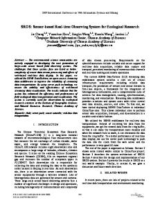
Fig. 3. Activation energy for the thermal dark current (plotted for the largest spikes only).
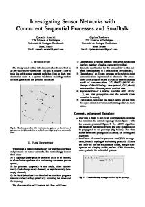
Fig. 1. Dark image from an active pixel sensor. The two bright regions received 10 MeV proton irradiation. The left region received 3:6 10 p/cm (2 krd) and the right, 7:2 10 p/cm (4 krd). The remainder (including the shift registers and on-chip ADC) was masked so that it was not irradiated.
2
2
Fig. 4.
Histograms of dark current density at 10 C.
0
Fig. 2. Thermal dark current density at 20 C (dark signal with fixed pattern noise subtracted) after 1 krd 10 MeV protons.
(FPN) does not depend significantly on integration time or temperature. Fig. 1 shows a typical dark image after exposure to 10 MeV protons and Fig. 2 a histogram of the thermal dark current density at 20 C. (after FPN is subtracted). Single pixel, dark current spikes (“hot pixels”), due to displacement damage, are seen and Fig. 2 is very similar in appearance to histograms from proton irradiated CCDs (see for example, [9]). However the maximum spike amplitude ( 1000–2000 electrons/pixel at 20 C) was roughly a factor two less than that seen in n-channel CCDs (e.g. the CCD02 and CCD05 from Marconi Applied Technologies or the TH7863D from Thompson TCS). This difference is likely to be due to a different electric field distribution within the pixel, leading to a different degree of field-enhancement. Evidence that field-enhancement is taking place (as it does in CCDs [10]) comes from the temperature behavior of the dark current. For both bulk and surface dark current the dependence on temperature follows the empirical relation: Dark Current
constant
(1)
where is Boltzmann’s constant and is the absolute temperis an activation energy, which is roughly 0.63 eV for ature. silicon [11]. However, when there is an electric field larger than 10 V/cm, the dark current is increased and the activation energy is lowered [10]. This is shown in Fig. 3 for the active pixel sensor.
Fig. 5. Histograms of dark current density at three temperatures, scaled to the dark current value at 10 C using an activation energy of 0.63 eV.
Fig. 6. Random telegraph signal behavior of the dark signal for a proton irradiated device.
Fig. 4 shows histograms for all the dose regions, this time at 10 C and Fig. 5 gives the histograms obtained at three different temperatures but scaled to 10 C using an activation energy of 0.63 eV. The good superposition shows that most (all but the field enhanced ones) vary with temperature as expected (see also Fig. 11). The majority of the brightest pixels (and 50% of the total) were found to show Random Telegraph Signal (RTS) behavior (Fig. 6), as occurs also in proton irradiated CCDs [12]. Some pixels were found to show fluctuations which were a large
2482
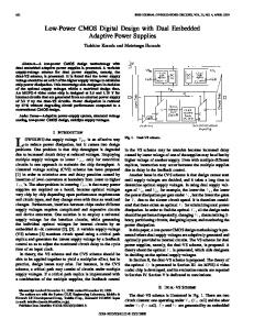
Fig. 7. Average responsivity (normalized to the value for the un-irradiated region).
IEEE TRANSACTIONS ON NUCLEAR SCIENCE, VOL. 47, NO. 6, DECEMBER 2000
irradiation.) The responsivity changes could be due to several causes: a) Decrease in minority carrier lifetime (and hence diffusion length, ) due to displacement damage. Since the volume of the photodiode is small, most of the charge is collected by diffusion. b) Decrease in gain of the in-pixel transistor, due to total ionizing dose effects. c) Change in the electric field distribution within a pixel (due to total ionizing dose) causing a change in the fraction of charge collected by drift rather than diffusion. The absence of a change with cobalt-60 irradiation suggests a displacement damage mechanism, where the diffusion length varies according to: (2) where is a damage constant and the proton fluence. A typ/cm for 10 MeV protons [13]. ical value for is then (1) can be re-written as: If the change in is (3)
and for small Fig. 8. Bright field image (dark signal subtracted) for the same proton-irradiated device as shown in Fig. 1. The image was taken 7.5 months after irradiation. Other images taken immediately after irradiation were of similar appearance. After 14 months, however, the loss in responsivity had annealed.
fraction (up to nearly 100%) of the spike size—unlike in previous CCD studies where the largest fluctuations were 10%. However, recent (so far unpublished) work on small pixel CCDs (the 13 m 13 m pixel CCD47-20 from Marconi Applied Technologies) has shown that large fluctuations are possible in proton-irradiated CCDs also. 2) Responsivity: Flat field illumination revealed a decrease in responsivity for the proton irradiated regions of each device, immediately after irradiation, and also when re-measured 7.5 months after irradiation. The change was 30% after p/cm and was independent of temperature, as shown in Fig. 7. The image shown in Fig. 8 (taken using broadband visible illumination) clearly shows the loss in responsivity in the (darker) irradiated regions—the same regions are brighter in the dark image of Fig. 2. After 14 months storage (again, unbiased at room temperature) the loss in responsivity had annealed out—and in fact turned into a small increase in responsivity. With cobalt-60 irradiation, the whole device receives the same total dose and it is not possible to compare the response of irradiated and unirradiated regions in one image; hence the measurement accuracy was reduced to roughly 10%. No change in responsivity could be detected at this 10% level krd(Si). (Note, though, that even at the highest dose used the cobalt-60 was at a much lower dose rate than the proton
: (4)
If we assume that the responsivity varies exponentially with the diffusion length then, to a first approximation the responsivity fluence of will also vary exponentially. However, to get a p/cm , as indicated by Fig. 7, would imply a rather large value of 100 m for the pre-irradiation diffusion length , and also that the response changes significantly as changes ). This seems (i.e., that the characteristic length for the pixel unlikely since spot illumination shows that most charge is collected within a 25 m pixel both for green (shallow absorption length) and red (deep absorption) light. Also it would be difficult to explain the “sudden” annealing which occurred between 7.5 and 14 months. The results of the next section show that sudden annealing (via turn-off of parasitic leakage paths) does occur with this sensor. So it is plausible that total ionizing dose is the cause of the responsivity change; though annealing would have to have been more significant for the cobalt-60 irradiation than in the high dose rate proton case. Note that proton irradiation has been seen to cause changes in CCD dark current which were initially “anomalous” but which annealed slowly at room temperature [9]. Clearly further work will be needed to establish whether displacement or total ionizing dose damage is responsible for the change in responsivity. This is somewhat academic for the present sensor since the pixel architecture is being modified (to improve tolerance to leakage currents and to improve optical performance). What is important is that in further studies (on future versions of this device and other types of APS), responsivity is carefully measured both immediately after irradiation
HOPKINSON: RADIATION EFFECTS IN A CMOS APS
Fig. 9. Average thermal dark current density after cobalt-60 irradiation. Three devices were irradiated up to 6 krd(Si) and three up to 21 krd(Si). All devices were annealed at room temperature for 1 week and two of the 21 krd(Si) devices (#84 and #25) were further annealed for one week at 100 C.
Fig. 10. Increases in supply currents for devices biased during irradiation. There was no significant change for the devices which were not biased.
and after annealing. Measurements of optical spot profiles at different wavelengths may help to determine whether changes in charge diffusion length are important (charge diffusion causes charge to spread sideways into adjacent pixels before collection and can be determined using spot illumination). B. Cobalt-60 Tests Fig. 9 shows the evolution of the mean dark signal with total ionizing dose. A large increase was observed for all devices above 6 krd(Si), consistent with earlier IMEC proton tests. Measurements performed using short integration times confirmed that the fixed pattern noise did not change but that the increase was due to changes in the thermal dark current. Immediately after 21 krd the dark signal for both biased and unbiased devices was high enough to cause saturation of the image at a 0.75 MHz pixel rate at room temperature. After the bake at 100 C the average dark signal annealed to a low level, consistent with extrapolation from the low dose proton irradiation data. This indicates that the average dark signal after proton irradiation is largely due to ionization, rather than bulk damage. The supply current for the sensor and the digital ADC line also increased significantly in biased devices (but not the un-biased devices) as shown in Fig. 10, but these effects again annealed at 100 C with a return to normal performance. The increase in dark current was thermal in character and varied with an activation energy of 0.63 eV (Fig. 11). Measurements were also made of linearity, photo-response nonuniformity (PRNU) and full well capacity as well as threshold voltages and ADC parameters (differential and integral nonlinearity: DNL and INL) but no significant changes were seen up to the maximum total dose of 21 krd(Si). The
2483
Fig. 11. Change in average thermal dark signal with temperature (before annealing at 100 C).
clock high and low threshold voltages were measured by changing the clock levels for the three types of input structure used in the sensor (under computer control). The voltages at which the sensor switched between operational and nonoperational conditions were noted. Voltage shifts could be measured to an accuracy 30 mV and only two of the threshold shifts were large enough to be measured after 21 krd. These gave values of 10 and 15 mV/krd(Si) before annealing with return to normal after 168 hours at room temperature, remaining unchanged after 168 hours at 100 C. Thus the gate threshold shift is negligible for space applications. The INL and DNL of the on-chip ADC were measured by de-coupling the sensor output from the ADC and applying a slow voltage ramp to the ADC input, synchronized to the sensor clocks. The resultant “ramp” images were histogrammed to determine the DNL or analyzed for deviations from a straight ramp (for the INL). The performance of the present ADC was poor (effectively it operated at 7 bits only), though this was unchanged with radiation. The next version of the sensor will have a 10-bit ADC. C. Latch-Up Tests Due to beam time constraints the maximum LET used ions at 60 incidence) but no was 28 MeV/mg/cm (Ar latch up was seen in the sensor at this LET for a fluence ions/cm . The supply to the on-chip ADC was of separately monitored and the ADC was seen to latch-up at an LET of 19.9 MeV/mg/cm with an average cross section of cm /device but not at 14.1 MeV/mg/cm (Ar ions ions/cm . However at normal incidence), at a fluence of the ADC was of an old design and will be replaced for future versions of the device. It is in any case possible to operate the sensor with an external ADC. IV. SUMMARY This study has characterized the radiation-induced dark current of the APS in detail. Proton effects are similar to those observed in CCDs, though the amplitude of the largest (field enhanced) spikes was slightly reduced. Random telegraph fluctuations were seen in proton irradiated pixels, many of which were a large fraction of the spike amplitude. The electronic fixed pattern noise was not changed by irradiation and remained at 200 electrons rms. The average dark current increased dramatically above 6 krad(Si) cobalt-60 but returned to a lower level (consistent
2484
IEEE TRANSACTIONS ON NUCLEAR SCIENCE, VOL. 47, NO. 6, DECEMBER 2000
with an extrapolation of lower dose data) after annealing. At the same time that the large dark current increase occurred, the device supply current also increased (but only for devices biased and clocked during irradiation). The supply current returned to its pre-radiation level after annealing. These results suggest that parasitic leakage paths (in isolation oxides) were turned on at 6 krad but were turned off when annealed. Flatband shifts in the gate oxides were not significant (being at most 15 mV/krad and annealing to pre-radiation levels). Large changes in the responsivity were seen after proton irradiation but these annealed during the period 7.5 to 14 months after irradiation. (The storage was unbiased at room temperature.) The change after 21 krd(Si) cobalt-60 was less than 10%. The cause of the responsivity changes is not known at this time. Either a displacement damage or a total ionizing dose mechanism is possible, though the annealing behavior suggests the latter is more likely. However the results show that measurement of responsivity should be an important part of future APS studies (unlike the CCD case where responsivity changes have not been seen at these radiation levels). The on-chip ADC was seen to latch up at 19.9 MeV/mg/cm and this would make it unsuitable for use in the space environment, though as mentioned above the ADC was of an old design and will be replaced for future versions of the device. It is in any case possible to operate the sensor with an external ADC (as was done for detailed performance characterization). Although only tested to a relatively low LET (28 MeV/mg/cm ) the absence of latch up at that level suggests that it would be a rare occurrence for most space missions. ACKNOWLEDGMENT Particular thanks are due to the project officer at ESTEC, A. Mohammadzadeh for guidance and support, G. Berger (UCL,
Belgium), K. Atkins (Sira) and R. Harboe-Sørensen (ESTEC) for assistance during the heavy ion irradiations and B. Nickson (ESTEC) for assistance with the Cobalt-60 irradiations. REFERENCES [1] D. Purll, P. Adolph, D. Uwaerts, and K. Weible, “A new technology attitude sensor,” in Proc. 4th ESA Int. Conf. On Spacecraft Guidance, Navigation and Control Systems, Feb. 2000, ESA SP-425, pp. 267–272. [2] C. C. Liebe, E. W. Dennison, B. Hancock, R. C. Stirbl, and B. Pain, “Active pixel sensor (APS) based star tracker,” in Proc. 1998 IEEE Aerospace Conference, 1998, pp. 119–127. [3] O. Saint-Pe, R. Davencens, M. Tulet, P. Magnan, C. Cavadore, A. Gautrand, Y. Degerli, F. Lavernhe, and J. Farre, “Development and characterization of active pixel sensors for space applications,” in Proc SPIE, vol. 3440, 1998, pp. 24–36. [4] G. Meynants, B. Dierickx, and D. Scheffer, “CMOS active pixel image sensor with CCD performance,” in Proc SPIE, vol. 3410, 1998, pp. 68–76. [5] B. R. Hancock and G. A. Soli, “Total dose testing of a CMOS charged particle spectrometer,” IEEE Trans. Nucl. Sci., vol. 44, pp. 1957–1964, Dec. 1997. [6] M. Cohen and J. P. David, “Radiation effects on active pixel sensors,” in Proc. RADECS 1999, 2000, pp. 450–456. [7] J. Bogaerts and B. Dierickx, “Total dose effects on CMOS active pixel sensors,” in Proc SPIE Photonics West, San Jose, Jan. 24, 2000. [8] G. Berger, G. Ryckewaert, R. Harboe-Sorensen, and L. Adams, “CYCLONE—A multipurpose heavy ion, proton and neutron SEE test site,” in Workshop Record, 1997 RADECS Conference Data Workshop, 1997, pp. 51–55. [9] G. R. Hopkinson, “Radiation effects on CCDs for spaceborne acquisition and tracking applications,” in Proc. RADECS 91, 1992, pp. 327–332. [10] J. R. Srour and R. A. Hartmann, “Enhanced displacement damage effectiveness in irradiated silicon devices,” IEEE Trans. Nucl. Sci., vol. 36, pp. 1825–1830, 1989. [11] G. R. Hopkinson, “Radiation-induced dark current increases in CCDs,” in Proc. RADECS 93, 1994, pp. 401–408. , “Proton irradiation induced RTS in CCDs,” in Proc 14th Int. Conf. [12] on Noise in Physical Systems and 1/f Fluctuations, C. Claeys and E. Simoen, Eds. Singapore: World Scientific, 1997, pp. 218–223. [13] E. A. Burke, “Energy dependence of proton-induced displacement damage in silicon,” IEEE Trans. Nucl. Sci., vol. 33, pp. 1276–1281, 1986.