Placement Optimization for MP-DSAL Compliant Layout Seongbo Shim†‡, Woohyun Chung†, and Youngsoo Shin† † Department of Electrical Engineering, KAIST, Daejeon 34101, Korea ‡ Samsung Electronics, Hwasung 18448, Korea Abstract—Sub 10-nm technology node requires contacts whose size and pitch are beyond optical resolution limit. Directed selfassembly lithography with multiple patterning technology (MPDSAL) has been actively studied to support such fine features. In MP-DSAL, layout decomposition is a key problem, in which close contacts are clustered and assigned to one of masks (or colors). Many practical contact layouts are not MP-DSAL compliant in a sense that layout decomposition is not perfectly performed leaving a few coloring conflicts and unmanufacturable contact clusters. We propose to optimize placement so that layout becomes MPDSAL compliant. A simple cell flip is employed for this purpose, and placement optimization is formulated as ILP; a practical heuristic is then proposed. Experiments demonstrate that very marginal 0.5% of cells are flipped to achieve our goal.
Mask-1
Contact cluster
GP images
GP (a)
(b)
Mask-2
(c) Contacts after etch
Polymer A
Polymer B
I. I NTRODUCTION
1 We focus on contacts in this paper, but MP-DSAL is applicable to both contacts and vias.
(e)
(f)
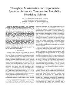
Fig. 1. MP-DSAL process: (a) contact clusters, (b) GP images, (c)–(d) multiple patterning to create GPs on a wafer, (e) GPs filled with BCPs, which are then self arranged, and (f) contact after polymer B is etched away.
100 DSA defect probability [%]
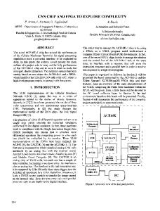
In sub 10-nm technology, very small size and pitch of contacts beyond optical resolution limit are required. In MPDSAL, contacts1 that are physically close are clustered as shown in Fig. 1(a). A contour that surrounds each contact cluster, called a guide pattern (GP) image, is synthesized (Fig. 1(b)). If GP images are too close, their mask images are synthesized on different masks, which then go through MP process to form the final GPs on a wafer (Fig. 1(c) and (d)). Each GP is filled with block copolymers (BCPs), strings of hydrophilic and hydrophobic polymers, which are self arranged due to forces between the polymers and GP wall (Fig. 1(e)). One type of polymer (polymer-B) is etched away, which leaves final contacts (Fig. 1(f)). In the basic DSAL without MP, contact clustering is uniquely determined [1]. However, larger and complex GP with many member contacts is more likely to cause patterning failure and so is difficult to manufacture [2]; as shown in Fig. 2, the probability that a GP causes a defect is 0% if only the GP contains less than 3 contacts or 3 linearly-aligned contacts in our experiment. This can be mitigated in MPDSAL by splitting large contact cluster into smaller ones, and assigning them on different masks. Corresponding problem of contact clustering and mask assignment, called MP-DSA decomposition problem, is shown to be NP-complete [3]. ILP-based approach [3] gives an optimum solution, but is applicable to only small circuits. One heuristic [4] is to solve MP-DSA decomposition for each cell row, but many color conflicts occur between adjacent cell rows.
(d)
80 60 40 20 0 1
2
3
4
5+
# Contacts in a cluster
Fig. 2.
DSA defect probability of various GP shapes.
To remove such color conflicts, it is required to adjust positions of contacts that cause the conflicts. In this context, we propose post-placement optimization, whose goal is to minimally perturb cell placement so that MP-DSA decomposition can be successfully finished without any conflicts. We perform MP-DSA decomposition for each cell in a library, and enumerate all possible decomposition solutions in advance. For cell each row in a given placement, we flip some cells to find the best placement that has no color conflicts between adjacent cells in the row; this is formulated as finding paths in
Contact cluster
Contact
Mask1
Mask3
...
Mask2
(a)
(b)
(c)
Fig. 3. MP-DSA decomposition solutions for one standard cell: (a) and (b) have the same contact clusters with different colors, and (c) has different clusters. Cell boundary
Color conflict
Merged cluster
we find all available mask assignments by brute force search. A cell may have multiple configurations of contact grouping, each of which has multiple mask assignment results, as shown in Fig. 3. This approach is exhaustive (it takes about 10 hours for 1,000 cells in our library), but required only once for a library, and the result can be used for many circuits using the library. We then abut two cells that are decomposed, and check whether the cell pair has a color conflict in-between. We check this for all possible cell pairs including cell flipping with all decomposition solutions, and the results are arranged as a table, which will be referred to by post-placement optimization in Section II-B and II-C. As a result, the size of the table is at most 4 × (m × n)2 , where m is the number of cells in a library and n is the maximum number of decomposition solutions of a cell. Note that in some cell pairs (see Fig. 4), clusters that cause a color conflict can be merged since the clusters are close enough and the merged one is still manufacturable; these cell pairs are regarded as conflict free in the table. B. Placement Optimization for Cell Row
(a)
(b)
Fig. 4. (a) A color conflict occurs between two close clusters and (b) they are merged removing the conflict.
a directed acyclic graph (DAG). Final placement is determined in a way as to select one placement in every cell row while no color conflicts occur between adjacent rows and minimum number of cells are flipped; this can be formulated as ILP, which we show, and a graph-based heuristic is also proposed for the sake of runtime. The remainder of this paper is organized as follows. In Section II, our post-placement optimizations is presented including how to solve MP-DSA decomposition for each cell, how to find best placements for each cell row, and how to determine the final placement. In Section III, our methods are demonstrated using a few test circuits in 7 nm technology. The paper is summarized in Section IV. II. P OST-P LACEMENT O PTIMIZATION A. MP-DSA Decomposition of Standard Cells It is very difficult to solve MP-DSA decomposition problem for whole contact layout in a placement due to large number of possible contact grouping and mask assignment. Fortunately, however, contact layouts are embedded in a standard cells, which are repeatedly placed in a placement, and the number of contacts in a cell layout is manageably small. So, we apply MP-DSA decomposition to each library cell in advance, and will use the resulting solutions for whole contact layout in a placement. For each cell, we first enumerate all configurations of contact groping using only manufacturable cluster shapes, i.e. clusters with 0% defect probability. For each configuration,
For a given placement of a circuit, we divide each cell row into small row segments in a way that abutted cells are included in the same segment, as shown in Fig. 5(a). If there is one (or more) whitespace of one poly-pitch width between two cells, no color conflicts occur between the two cells. So, we can solve MP-DSA decomposition problem for each row segment independently. Let us assume a row segment that consists of 5 cells denoted by C1 , C2 , · · · , C5 as illustrated in Fig. 5(a). We want to determine orientation of each cell in the segment so that MPDSA decomposition can be finished without no color conflicts. We address this problem using a directed acyclic graph (DAG) as shown in Fig. 5(b). Each cell position corresponds to two vertex groups: vertices in one group (white-colored vertices) correspond to possible decomposition solutions of the cell; and vertices in another group (grey-colored vertices) correspond to those when the cell is flipped. We then insert an edge between two vertices of adjacent cell positions (e.g. C1 and C2 ), if the corresponding pair of decomposition solutions has no color conflict, which is identified by simply looking up the table that is constructed in Section II-A; otherwise, no edge is inserted. Two dummy vertices, s and t, are added to finalize the graph. We then find all possible paths from s to t, which correspond to best placements of the row segment. In some adjacent cell positions (see C2 and C3 in Fig. 5(b)), vertices are fully connected. This implies that the cell pair is always free from color conflict regardless of what decomposition result we choose. This allows us to split the graph into two small ones as shown in Fig. 5(c); accordingly, corresponding row segment is also split into two small segments. C. Considerations of Inter-Row Conflict The best placements for each row segment may still have some color conflicts between adjacent segments in different cell row, so called inter-row conflicts. To finalize post-
Whitespace
Cell
Duplication conflict edge
Row segment
Vertex group C11
C12
C1 C31
C13 C2
C32
C14 C3
C4
C33
C34
Color conflict edge Vertex weight
C15 1
C5
2
0
0
0
2
1
0
C35 2
2
3
0
1
1
1
0
(a)
Decomposition solutions of non-flipped cell C1
1
1 C2
C3
C4
0
C5
s
2
0
2
-1
(a)
t 1
Decomposition solutions of flipped cell
C1
(b)
2
C2
C3
C4
0
2
3
1
C5
0
1
1
1
0
2
1
0
1
0
0
2
2
-1
(b) s
t
s
t
Fig. 6.
Conflict graph (a) before and (a) after partitioning.
(c)
Fig. 5. (a) A placement, (b) a DAG of a cell row segment, (c) the DAG is divided into small DAGs. TABLE I N OTATIONS OF ILP FORMULATION Pi j Fi j Ci jkl xi j
j-th best placement of i-th row segment the number of flipped cells in Pi j a pair of Pi j and Pkl that have inter-row color conflict (i �= k) 1 if Pi j is selected, 0 otherwise
placement optimization, we need to carefully select one best placement for each row segment while no inter-row conflicts occur and minimum number of cells are flipped. This problem can be formulated as an ILP, which will be used as a reference for comparison, and a graph-based heuristic for a circuit of practical size is also proposed. 1) ILP Formulation: The notations that we use for ILP formulation are summarized in Table I. Our problem is to determine the value of xi j with objective of minimizing sum of Fi j for selected Pi j : Minimize
∑ Fi j xi j ,
∀ i and j
(1)
subject to:
∑ xi j = 1,
∀i
(2)
∀ Ci jkl
(3)
∀j
xi j + xkl ≤ 1.
Equation (2) is a constraint that only one best placement should be selected in each row segment. Inequality (3) avoids inter-row conflict between two best placements from different row segments. 2) Graph-Based Heuristic Algorithm: We construct a conflict graph as follows. A best placement of each row segment corresponds to a vertex, whose weight value is determined by the number of flipped cells in the placement, as shown in Fig. 6(a). If two vertices are originated from the same row segment, they belong to the same vertex group and have an edge in-between (see black edge); this corresponds to equation (2) in the ILP formulation. Two vertices also have an edge (see red edge), if corresponding two placements have inter-row conflict; this corresponds to inequality (3) in the ILP formulation. The goal of our algorithm is now to select one vertex from every vertex group while the selected vertices are not connected and sum of their weight values is minimized. The algorithm finds all maximum independent sets (MISs) of the input graph, which correspond to placements that have no color conflict at all. We then select one with smallest weight sum as a solution. Finding MIS is NP-hard problem and the input graph is large, so we partition the graph for the sake of runtime. If a vertex group has a vertex that has no color conflict edge, it is first selected as a member of MIS, and other vertices in the group and their connected edges are removed accordingly, as shown in Fig. 6(b). If there are multiple vertices that have no color conflict edge in a group, one with smallest weight
TABLE II C OMPARISON OF FOUR APPROACHES WITH TRIPLE PATTERNING
Circuits spi mem_ctrl usb_func b14 b21 b22 b18 ethernet b19
# Contacts 9168 10289 10709 14781 39812 72201 145451 301422 519045
MP-DSA decomposition without cell flipping Row-by-row [4] ILP [3] # Conflicts # Conflicts 16 0 52 0 173 0 152 3 327 27 385 Time-out 501 Time-out 892 Time-out 1139 Time-out
value is selected. We repeat this until no group has such vertex without color conflict edge. Our algorithm is then applied to each partitioned graph. Resulting MISs from each graph are then merged and correspond to an optimum placement.
III. E XPERIMENTS We implemented our ILP and heuristic algorithm using Perl scripts. GUROBI [5] was used as an ILP solver. A few test circuits from Open Cores [6] and ITC99 [7] are synthesized using 28-nm industrial library; contact layout is appropriately shrunk so that the layout can follow 7-nm design rule, which we assume in this paper. Contact size is assumed to be 15nm by 15nm, poly and metal track pitch are set to 44nm and 35nm, respectively. The number of contacts ranges from 10k (spi) to 500k (b19) as shown in Table II. Triple patterning with ArF immersion lithography is assumed. If center-to-center distance of two contacts is smaller than 55nm, they may be grouped in the same cluster or grouped in different clusters with different mask colors; if the distance is larger than 55nm and smaller than 120nm, they have to grouped in different clusters with different mask colors; for distance larger than 120nm, they are grouped in different clusters, which may have any color. Two existing methods of MP-DSA decomposition (Row-byrow [4] and ILP [3]), in which post-placement optimization is not performed, were also implemented for comparison. Many color conflicts remain in Row-by-row (3rd column) since interrow conflicts are not considered. ILP (4th column) completed decomposition without any color conflicts (or with very small number of conflicts) in 5 small circuits. Our ILP removed all remaining conflicts by flipping some cells (5-6th column) in 6 small circuits; please note that if no conflict occurs in ILP, our ILP also completes the decomposition without cell flipping (see spi, mem_ctrl, and usb_func). Our heuristic algorithm removed all conflicts in all circuits; more cells were flipped than ILP due to sub-optimality of our heuristic, but it is at most less than 0.5% of total number of cells.
MP-DSA decomposition with cell flipping Our ILP Our heuristic # Conflicts # Flipped cells # Conflicts # Flipped cells 0 0 0 0 0 0 0 0 0 0 0 16 0 28 0 42 0 152 0 194 0 207 0 311 Time-out 0 527 Time-out 0 781 Time-out 0 1025
IV. C ONCLUSION Existing MP-DSA decomposition methods leave many color conflicts because layout is not MP-DSAL compliant. We have proposed post-placement optimization, whose goal is to flip minimum number of cells so that MP-DSA decomposition can successfully be performed. We enumerate all possible decomposition configurations for each standard cell in advance, which are referred to during post-placement optimization for each cell row. We then select one best placement in every cell row in a way that no color conflicts occur between adjacent cell rows while minimum number of cells are flipped. This problem has been formulated as ILP, and heuristic algorithm has also been proposed. Our ILP and heuristic algorithms have been demonstrated in 7-nm technology. ACKNOWLEDGMENT This work was supported by the National Research Foundation of Korea (NRF) grant funded by the Korea government (MSIP) (No. 2015R1A2A2A01008037). R EFERENCES [1] H. Yi, X. Bao, R. Tiberio, and P. Wong, “Design strategy of small topographical guiding templates for sub-15nm integrated circuits contact hole patterns using block copolymer directed self assembly,” in Proc. SPIE Advanced Lithography, Mar. 2013, pp. 1–9. [2] S. Shim, W. Chung, and Y. Shin, “Defect probability of directed self-assembly lithography: fast identification and post-placement optimization,” in Proc. Int. Conf. on Computer Aided Design, Nov. 2015, pp. 404–409. [3] Y. Badr, A. Torres, and P. Gupta, “Mask assignment and synthesis of DSA-MP hybrid lithography for sub-7nm contacts/vias,” in Proc. Design Automation Conf., Jun. 2015, pp. 70:1–70:6. [4] Z. Xiao, C. Lin, M. D. Wong, and H. Zhang, “Contact layer decomposition to enable DSA with multiple-patterning technique for standard cell based layout,” in Proc. Asia South Pacific Design Automation Conf., Jan. 2016, pp. 95–102. [5] Gurobi Optimization, Inc., “Gurobi optimizer reference manual,” 2015. [Online]. Available: http://www.gurobi.com/. [6] “Opencores,” http://www.opencores.org/. [7] “ITC99,” http://www.cerc.utexas.edu/itc99-benchmarks/.