Noname manuscript No. (will be inserted by the editor)
Pivoting Based Manipulation by a Humanoid Robot Eiichi Yoshida · Mathieu Poirier · Jean-Paul Laumond · Oussama Kanoun · Florent Lamiraux · Rachid Alami · Kazuhito Yokoi
Received: date / Accepted: date
Abstract In this paper we address whole-body manipulation of bulky objects by a humanoid robot. We adopt a “pivoting” manipulation method that allows the humanoid to displace an object without lifting, but by the support of the ground contact. First, the smalltime controllability of pivoting is demonstrated. On its basis, an algorithm for collision-free pivoting motion planning is established taking into account the naturalness of motion as nonholonomic constraints. Finally, we present a whole-body motion generation method by a humanoid robot, which is verified by experiments.
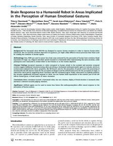
Fig. 1 Humans often manipulate bulky objects by supporting them on its corner without lifting.
Keywords Manipulation · Humanoid · Motion planning · Whole-body motion 1 Introduction Thanks to recent progress in their hardware and control, humanoid robots are expected to execute sophisticated tasks to assist or substitute humans. One of those applications is manipulation of cumbersome object, which humans often manipulate without lifting but by using the contact with the ground (Fig. 1). In this Preliminary results related to this paper have been presented in 2007 IEEE/RSJ International Conference on Intelligent Robots and Systems and 2008 IEEE International Conference on Robotics and Automation. E. Yoshida and K. Yokoi Intelligent Systems Research Institute, National Institute of Advanced Industrial Science and Technology (AIST), 1-1-1 Umezono, Tsukuba, 305-8568 Japan. E-mail: {e.yoshida, kazuhito.yokoi}@aist.go.jp M. Poirier, J.-P. Laumond, O. Kanoun, F. Lamiraux, and R. Alami LAAS-CNRS, University of Toulouse; UPS, INSA, INP, ISAE ; LAAS ; 7, Avenue du Colonel Roche, 31077 Toulouse, France. E-mail: {mpoirier, jpl, okanoun, florent, rachid}@laas.fr
Fig. 2 An experiment of whole-body pivoting manipulation.
research we investigate a planning method for this type of pivoting based manipulation of a large object using both arms of a humanoid robot as shown in Fig. 2. This method has advantages such as dexterity, stability and adaptability over other methods like pushing or lifting [1,2]. It is also advantageous because it allows backward motion. For those reasons, pivoting based manipulation can potentially widen the capacity of manipulation of humanoid robots. There have been many studies on motion planning for manipulation tasks as comprehensively summarized in [3]. Pivoting is classified as “non-prehensile manipu-
2
lation” that includes such methods as pushing or tumbling. Recent advances in analysis on robotic manipulation have verified the controllability of various manipulation methods that is an important property for the path planning. For example, Bicchi et al. studied the property of the reachable configurations of polyhedral object by tumbling [4]. Meada et al. proposed a method for planning the motion of fingers to manipulate an object by combining different types of non-prehensile manipulation [5]. On the other hand, the motion control methods for whole-body humanoid manipulation tasks are actively being studied: for instance, pushing [6–8] or lifting [9– 11] bulky or heavy objects. We have also conducted a kinematic analysis on the pivoting manipulation by a humanoid robot and proposed a basic motion generation method by handling the upper and lower body motions separately [2]. However, those research efforts remain on the development of each elementary motion generation and have not yet been linked to collision-free motion planning. Recently, several researchers have investigated the whole-body humanoid motion planning including object manipulation and locomotion in an environment with movable objects [12,13]. They are nevertheless more oriented to the navigation of the robot than the manipulation planning. In this context, this paper has two main contributions. The first is the establishment of an algorithm for collision-free planning of pivoting sequences based on the analysis on the controllability. The second contribution is the whole-body motion generation for a humanoid robot to perform the manipulation, which is validated by experiments. We believe this work contributes to research on autonomous mobile manipulation through the establishment of a planning method for pivoting based manipulation of a large object by a whole-body humanoid motion. For the planning algorithm development, we first demonstrate that any collision-free path for the freesliding object may be approximated by a sequence of collision-free pivoting motions. This property is shown by introducing the notion of small-time controllability in Section 2. As a consequence, we take a two-stage motion planning approach: first a collision-free path is computed, and then it is iteratively approximated by a sequence of pivoting motions. We also consider the naturalness of the motion. It is preferable for the robot to walk either forward or backward and to avoid sideways steps. When walking in this way, the moving direction remains tangent to the path like a wheeled mobile robot, which is known as nonholonomic constraints. It has recently been shown that those constraints account for natural human locomotion [14]. The motion
planning method proposed in Section 3 therefore benefits from well experienced approaches on the probabilistic sampling approach [15,16] in nonholonomic motion planning [17]. The whole-body motion generation for pivoting manipulation by a humanoid robot is presented in Section 4. After the planning of the complete sequence of pivoting manipulation, we make use of a whole-body motion generator [18] including dynamic stepping motions, which is based on a generalized inverse kinematic (IK) method (e.g., [19,20]). This method allows the humanoid robot to move the arm and the leg at the same time without functional decomposition of degrees of freedom (DOF). The proposed method is validated through hardware experiments of the humanoid robot platform HRP-2 in Section 5.
2 Analysis of Geometric Property of Pivoting We here introduce a model of pivoting manipulation that we are considering and show that it is small-time controllable.
2.1 Definition of Pivoting Motion An edge of the convex hull of a polyhedral object is selected as the supporting edge (Fig. 3) with which the pivoting is performed as follows. The robot first inclines the object to support on a vertex to have a single contact point on the floor. A rotation is then performed along the vertical axis on that vertex. Finally, the edge is attached to the floor to change the supporting contact point. In this pivoting motion, the inclination angle can be as small as possible by assuming sufficient capacity of
Rotation axis
Pivoting vertex
Supporting edge
Fig. 3 Supporting edge. The pivoting sequence is planned using rotation along a vertical axis on one of the vertices of this edge.
3
the robot. We can therefore model the problem of 3D pivoting of polyhedral objects as the problem of pivoting a 2D segment around its endpoints. Such a modeling does not reduce the scope of the general problem. The planning of pivoting sequences becomes a problem of displacing a line segment AB on a plane by rotating itself alternatively at one of its extremity points A and B in Fig. 4.
A system is said to be controllable if it may reach any arbitrary configuration qgoal from any other qinit [21]. It is said to be small-time controllable if the set of admissible configurations Reachq (T ), which can be reached from configuration q before a given time T (> 0), contains a neighborhood of q. This property should hold at any configuration q for any T . It means that the system can move anywhere in the area η without leaving an imposed neighborhood V as shown in the left of Fig. 5. Small-time controllability is a critical property in path planning. The main consequence is depicted in Fig. 5: any collision-free path can be approximated by a sequence of both collision-free and admissible motions as follows. Starting from the initial configuration qinit , take any collision-free neighborhood V1 . Then the system can advance to a configuration q1 on the path within Reachq1 (T ) without going out of V1 . The same procedure is repeated until the system reaches the goal configuration qgoal (Fig. 5). This type of analysis plays an important role in nonholonomic motion planning [17]. Small-time controllability can be proven by applying the so-called Lie Algebra Rank Condition (LARC) [21] in the following way. We here deal with a control system for the moving line segment of length 2l (Fig. 4). The configuration of the line segment is expressed as that of its center O(x, y) and its orientation θ. At each step of the pivoting sequence, two elementary rotating motions are allowed for the segment. L (x, y)
B
A
R
y
θ
V
qgoal
η
q
V1
q1
Approximated collision-free path
Collision-free path
Fig. 5 A system is small-time controllable from q if Reachq (T ) contains a neighborhood of q for all neighborhoods V for any time T > 0.
2.2 Pivoting and Small-time Controllability
O
Reachq(T )
x
Fig. 4 Pivoting problem: displacing a line segment A or B
Let us now consider the left (counterclockwise) rotation around the point A. The vector field L for this motion is derived by calculating the tangent velocity of the point O at the configuration q(x, y, θ) as follows: ⎛ ⎞ −l sin θ L = ⎝ l cos θ ⎠ . (1) 1 The same computation applies for right turn; turning around the point B corresponds to a counterclockwise motion vector field ⎛ with associated ⎞ l sin θ R = ⎝ −l cos θ ⎠ . (2) 1 Then the pivoting control system is: q˙ = Lu1 + Ru2
(3)
where u1 , u2 are the input angles for the motion. Notice that u1 and u2 cannot be applied simultaneously. Now we aim to prove the property that the pivoting system is small-time controllable. It suffices to apply LARC by computing the Lie Bracket [L, R]. Let us recall that the k th component [f, g]k of Lie Bracket of vector field f and g is calculated by: n � ∂fk ∂gk (gi − fi ) (4) [f, g]k = ∂q ∂qi i i=1 where qi is the i th component of the configuration [21]. By applying this formula to our pivoting system, we obtain ⎛ ⎞ −2l cos θ [L, R] = ⎝ −2l sin θ ⎠ . (5) 0 The three vector fields L, R and [L, R] spans a three-dimensional space. Since the LARC condition holds, the pivoting polyhedron is a small-time controllable system. The reachable space from any starting configuration contains always a neighbor no matter how cluttered the environment is. Consequently, any collisionfree path planned without taking into account the pivoting constraint can be approximated by pivoting operations without collision.
4
3 Collision-free Pivoting Sequence Planning We need to define a method a method that computes an admissible path between two configurations. Even if a system is proven to be small-time controllable, devising such a method working practically is another story [17]. We therefore present a method for planning collisionfree pivoting sequence composed of two stages by taking into account the naturalness of the motion through nonholonomic constraints. In other words, the forward and backward motions are more privileged than sideways motions for ease of manipualtion and locomotion. At the first stage a collision-free path is planned (3.1), and then it is transformed into a sequence of pivoting motions at the second stage (3.2) by preserving small-time controllability. 3.1 Collision-free natural path planning The first stage of the algorithm is dedicated to the computation of a collision-free nonholonomic path. For this stage we make use of a standard technique of probabilistic motion planning [15,16] we summarize here. The robot together with the manipulated object is modeled as a rigid body whose geometry is their bounding volume. For the sake of the motion naturalness as stated in Section 1, such a rigid body is modeled as a car-like robot that is subject to two constraints: its wheels should roll and not slide (this is the nonholonomic constraint), and the curvature of an admissible path at any point should not be greater than some fixed threshold. The shortest length paths for such a system are the so-called Reeds and Shepp curves [22]. Reeds and Shepp curves are made of a sequence of arcs of a circle with minimum radius and straight line segments. The interest of Reeds and Shepp curves is its geometric property that satisfies small-time controllability [23]. To compute a collision-free nonholonomic path we use a probabilistic roadmap method that consists in building a graph whose nodes are collision-free configurations. Here we can apply any roadmap building method like diffusion (e.g. Rapidly-exploring random tree, RRT) or sampling method (e.g. sampling method (i.e. Probabilistic RoadMap, PRM) [15,16]. Among them, we utilize a more sophisticated and efficient variant of PRM [24]. During the search, two nodes are linked by an edge if and only if the Reeds and Shepp path between both corresponding configurations is collision-free. In this way, the motion planner eventually finds collision-free paths as connected components of elementary motions of the steering method. Then a path optimizer searches shorter paths by connecting configuration pairs randomly sampled on the initial path. In
x
y
(0, 0, 0 )
(-2.3, -1.76, -90 )
(a) Initial state
(b) Goal State
Fig. 6 Optimized collision-free path for a manipulated object and the humanoid robot using Reeds and Shepp curves. The path allows the humanoid to move the object away from the wall starting from the initial state (a) by taking advantage of backward motion. Then the path switches to forward motion to avoid obstacle and to move the object to the goal (b).
this study we employ the “adaptive shortcut” path optimization algorithm proposed by [25]. Figure 6 shows an example of an optimized path. The manipulated object is placed near the wall and supposed to be displaced on the other side of an obstacle. For simplicity, we here use a bounding volume including the humanoid and the object with some tolerance necessary for the pivoting based manipulation1 . As can be seen, the backward motion of Reeds and Shepp curve is utilized appropriately to move the object away from the wall. Then the path switches to forward motion to reach the goal by avoiding the obstacle. 3.2 Pivoting Sequence Generation Now we present how to convert the collision-free path computed at the first stage into a sequence of collisionfree pivoting sequences. In order to Reeds and Shepp curves, two elementary operators are employed: pivoting along a straight line segment and along an arc of a circle. The computation of the pivoting sequence along a straight line segment is illustrated in Fig. 7. Let L be the length of the straight line segment of the path to follow. As defined earlier, the length of the supporting edge is 2l. We introduce a rotation angle β such that the whole pivoting sequence results in a displacement of length L. The angle β and an integer N can be determined to satisfy L = 2N l sin β, without β exceeding the maximum value βmax that takes into account the constraint of the reachable area of robot arms. 1 Depending on the clutteredness of the environment, more precise bounding volumes can be used, like separately estimated swept volumes of upper and lower body motions.
5
L
2l
ing sequence. We should notice that this angle may be tuned for obstacle avoidance purpose. Indeed, the first stage of the algorithm provides a collision-free path that guarantees collision-freeness for the sliding supporting edge. Moving by pivoting along the planned path introduces some difference (see Fig. 9) with respect to the volume swept by the supporting edge when sliding along the path. As the rotation angle decreases, the final swept volume converges to the initial one. This property accounts for the small-time controllability of the pivoting system we have considered in Section 2. The 3D collision detection can be done by estimating the swept volume of the object attached to the supporting edge during the rotational motion. As a consequence, the two-stage strategy we have developed inherits from the probabilistic completeness of the motion planner used at the first stage. The approximation scheme by on pivoting sequence generation does not introduce any incompleteness thanks to smalltime controllability.
β 2β
1
2
N
Fig. 7 Transforming a straight line segment path into a pivoting sequence. The pivoting sequence is planned using rotation of the endpoints of the supporting edge. During the sequence, rotations of same angles are repeated to reach the endpoint.
The same principle applies to the arcs of a circle (see Fig. 8). Let R and θ denote the radius and the angle of the arc. We apply a sequence shown in Fig. 8 with a symmetrical motion such that the center of the line segment comes on the arc with perpendicular orientation, after two times β rotation at the left corner and one −2γ rotation at the right corner. The angle α and γ can be computed from l, R, and β as: α = arctan(
4 Whole-body humanoid motion
2l sin β ), R − l + 2l cos β
γ = β − α.
The generated pivoting sequence should be performed by the humanoid robot by using its two arms. The humanoid motion should be generated in such a way that constraints like dynamic balancing and arm manipulation motion are fulfilled at the same time. Moreover, stepping motions should be added in order to continue the manipulation when necessary. For this purpose we adopt a general framework of whole-body motion generation [18] including dynamic stepping motions. Based on a generalized inverse kinematic (IK) method (e.g., [19,20]), such tasks as center of mass (CoM) position, stepping and hand motions
(6)
Similarly to the case of the line segment, the value α and an integer M are determined so that β is smaller than βmax . We introduced the angle β as the closest value to the maximum value βmax to achieve the required pivotM
Obstacle
2
2β
l
l
1
2γ
θ
2α
2l
β 2l R
Fig. 8 Transforming an arc of circle path into a pivoting sequence. The regular sequence is composed of symmetric rotations. The center of pivoting line segment arrives at the end point of the arc with the perpendicular orientation.
Sequence with large rotation angle
Small rotation angle
Fig. 9 The swept volume of pivoting. It converges to the swept volume of the supporting edge along the straight line segment by reducing the rotation angles. Therefore, the original collisionfree Reeds and Shepp path can be converted into a collision-free pivoting sequence.
6
are treated with priorities. Since all the joints are involved to make those complex combined motions, we can expect better performance in the sense of reachable space than a functional decomposition utilized in [2]. In this section, we will describe a method for the wholebody motion generation for pivoting manipulation after briefly introducing the generalized inverse kinematics.
.
Hand trajectory
Robot / object motion manager Robot-object distance Stepping motion generator
Other constraints .
Upper-body direction Waist orientation ...
.
CoM trajectory Foot trajectory
Whole-body motion solver with generalized IK
4.1 Generalized Inverse Kinematics for Prioritized Tasks
Joint angles output
Let us consider a task x˙ j with priority j in the workspace and the relationship between the joint angle velocity q˙ ˙ is described by using Jacobian matrix, like x˙ j = J j q. For the tasks with the first priority, using pseudoinverse J# 1 , the joint angles that achieve the task is given: ˙ 1 + (I n − J # q˙ 1 = J # 1 x 1 J 1 )y 1
Pivoting motion sequence Object position
(7)
.
Fig. 10 Usage of generalized inverse kinematics utilized for whole-body motion for pivoting based manipulation.
where y 1 , n and I n are an arbitrary vector, the number of the joints and identity matrix of dimension n respectively. For the task with second priority x˙ 2 , the joint velocities q˙ 2 is calculated as follows [19]: ˆ # (x˙ 2 − J 2 q˙ ) + (I n − J # J 1 )(I n − J ˆ #J ˆ q˙ 2 =q˙ 1+J 1 2 2 2 )y 2 1 ˆ 2 ≡ J 2 (I n − J # J 1 ) where J (8) 1
where y 2 is an arbitrary vector of dimension n. It can be extended to the task of j th (j ≥ 2) priority in the following formula [20,26]: ˆ # (x˙ j − J j q˙ q˙ j = q˙ j−1 + J j−1 ) + N j y j j N j ≡N j−1 (I n −
ˆ #J ˆ j ), J j
ˆ j ≡ J j (I n − J
(9) ˆ# J ˆ J j−1 j−1 )
4.2 Whole-body motion generation by Generalized IK To perform the planned pivoting sequence, a wholebody motion generation framework based on the aforementioned generalize IK is built as illustrated in Fig. 10. In this framework, the whole-body motion manager receives the desired hand trajectories (Fig. 11) and keeps track of the current robot configuration. Then it computes the trajectories or constraints that are supplied to the generalized IK solver. Since the both hands are fixed to the box, all the DOFs of the arm are used to perform the computed hand trajectory. When the pivoting rotation requires large horizontal displacement, a stepping motion is planned at the same time of the hand motion. The stepping foot is determined depending on the rotation direction. Then the new foot position is computed in such a way that the foot keeps its orientation in parallel with the base
Fig. 11 Hand trajectory generated from the pivoting sequence. From the planned pivoting sequence of the object, trajectories of both hands are computed and supplied to the generalized IK solver.
Reeds and Shepp curves with an appropriate distance to the object. In this case of stepping, a dynamically stable stepping motion is generated as trajectories of the CoM and the foot using Zero Moment point (ZMP) based preview controller [27]. If the stepping is not necessary, like during the object inclining motion, the manager also provides the constraints of the CoM to keep balance. The CoM Jacobian [28] is utilized for the solver to deal with the CoM tasks. The generalized IK solver takes those trajectories and constraints as input tasks. Some other constraints are also given to the solver, for instance to keep the waist and the chest horizontal. This process is applied to each pivoting operation in the sequence.
7
Consequently, the tasks of generalized IK solver are defined as follows: Priority 1 : – CoM trajectory / constraint (2 DOFs) – Foot trajectory (6 DOFs, stepping) Priority 2 : Hand trajectory (6 DOFs × 2) Priority 3 : – Waist constraint (3 DOFs, Horizontal and height) – Chest constraint (2 DOFs, Horizontal) The CoM and foot tasks are given the highest priority to privilege the balance and the lower-body motion. Although the hand trajectories have the second priority, they are almost always achieved with the sufficient degrees of freedom of the upper-body. However, no additional constraint can be added to the arm motion when the number of DOFs of the task and the arms are the same, which is the case of HRP-2 with the both hands fixed on the object. The third tasks are added to maintain upright posture of the robot which is respected as much as possible after satisfying the tasks with higher priorities. The proposed planning method for pivoting manipulation by a humanoid robot has been implemented in a common software framework “Humanoid Path Planner” on the basis of the motion planning software kit KineoWorksTM [29] as shown in Fig. 12. The object-oriented architecture allows the users to define our planner of the whole-body pivoting motion as an inherited class of a general robot motion planner. The planner takes care of interaction with basic functions such as roadmap builder, path optimizer and collision checker. We also implemented the steering methods specific to the pivoting planning problem. Once the whole-body humanoid motion is generated, it is passed to the robot simulator and controller OpenHRP [30]. Whole-body robot motion
Start/goal positions
OpenHRP Robot controller
Generalized IK
Pivot motion planner
5 Experimental Results We have conducted the experiments with the humanoid robot platform HRP-2 [31] in the environment shown in Fig. 6 for whole-body motion planning for pivoting of a box-shape object. HRP-2 is 1.58m tall and weighs 58kg, with total 30 DOFs. It has 6-DOF arms and legs and also two rotational joints (pitch and yaw) at the chest that provides a wide workarea of upper-body. The radius is fixed as 1.0m for Reeds and Shepp curves and the width, depth and height of the box is 0.35m (= 2l), 0.32m and 1.1m that weighs 7kg. The robot holds the object by the point contact on the side faces at the point at 0.8m and 0.05m from the bottom and front face respectively. The maximal horizontal rotation angle β is set to 15◦ whereas the inclination angle is 5◦ . The initial and goal positions of the object are (0.0, 0, 0◦ ) and (-2.3, 1.76, -90◦ ) respectively. The hand trajectories are planned a few centimeters inside the box to keep the contact. A pole is placed at (-1.15, -0.8) as an obstacle. The execution time of the entire pivoting sequence is 281 seconds, which corresponds to 56200 command outputs at the rate of 5ms for each of 30 joints. The computation time was 291.7 seconds with a PC of Intel Core2 Duo CPU at 2.13GHz, which is comparable to the actual task execution time. Fig. 13 shows some snapshots of planned result of motion planning for pivoting based manipulation. The humanoid robot makes a backward motion to move the box object away from the wall along an arc of circle.
User Interface
Humanoid Path Planner Reeds & Shepp SM
Pivoting SM
Generic motion planner
Path optimizer Data flow Inherited classes on C++
Roadmap builder
Steering method (SM)
Collision checker Basic implementations
KineoWorksTM
Fig. 12 Architecture of Humanoid Path Planner framework that facilitates implementation of robotic motion planner according to specific problems.
Fig. 13 Snapshots of the planned result. The manipulated object is drawn transparently to show the robot motion. The Reeds and Shepp path allows the robot to use backward motions to move the object close to the wall. The snapshots show how the humanoid robot transports the object through combination of pivoting and stepping along the planned optimized Reeds and Shepp path.
8
Then it changes the motion direction to carry the object by avoiding the obstacle.
complish the long pivoting sequence. The average error of the final position of the carried object was 0.46m (0.31m and 0.35m short in x and y directions respectively), and 5◦ in orientation θ. The error 0.46m represents 9% of the length 5.1m of the whole trajectory of the carried object. This confirms that the manipulation
The experimental results are shown in Fig. 14 to validate the proposed method. The motion has been planned offline with the prior knowledge of the object and environment. As can be seen, the robot could ac-
(a)
(b)
(c)
(d)
(e)
(f)
Fig. 14 Experimental results. Starting from the initial position (a) with obstacle at right-hand side, the humanoid robot manipulates the object backwards away from the wall (b). After switching motion direction to forward (c), the robot continues to manipulate the object to the goal position by avoiding the obstacle (d-f).
Fig. 15 Detailed whole-body pivoting motion in backward direction. Starting from the initial configuration, the humanoid robot makes coordinated leg and arm motions. The robot rotates the object clockwise by supporting it on the left corner and stepping back with right leg.
9
has been executed relatively accurately considering the lack of sensor feedback of the object location during the manipulation. In Fig. 15, we can see that the robot executes the complex pivoting manipulation with a coordinated wholebody motion including simultaneous manipulation and foot-stepping. Those whole-body motions can be observed more clearly in the provided supplementary multimedia materials (movies).
6 Conclusions and Discussions In this paper we have presented a method for planning pivoting based manipulation by a whole-body humanoid motion. We have first demonstrated the small-time controllability of the pivoting manipulation. This analysis then leads to the establishment of a collision-free motion planner of pivoting sequence that benefit from welldeveloped sampling-based planning approach that guarantees the probabilistic completeness. The naturalness of the motion during manipulation is modeled as a nonholonomic constraint that orients the robot in the forward direction. Finally the generated pivoting sequence is transformed into whole-body humanoid motion through the generalized inverse kinematics. In the resulting whole-body motion, the humanoid robot moves the arms and the legs at the same time to perform the pivoting by keeping dynamic balance, as confirmed with the experiment with HRP-2 humanoid robot. The main limitations of the proposed method that may cause failures are the fixed holding configuration in planning and the lack of sensor feedback about the manipulation status in execution. Possible improvement for the planning issue is to increase its flexibility by allowing the humanoid to change the pivoting edge and hand placement. Pivoting edge switching has recently been addressed through a roadmap multiplexing approach to cope with narrow passages [32]. Optimizing the hand placement with certain criteria like stability or manipulability should also be addressed to make the proposed planning method more robust. Another extension of planning is to apply the proposed method to objects with smooth surfaces like a barrel in Fig. 1 so that the rolling point of the object can trace the basic path. The sensor feedback of the manipulation status such as object localization and also reaction force is important for the robot to reactively adapt the trajectory to unexpected disturbance during execution. The current implementation is open-loop as the robot executes the motion planned in advance even though it has feedback
in the joint control level and body stability. Since the computation time is already comparable with the execution time, we intend to improve the reactiveness of manipulation execution so as to detect and to correct errors in real-time. Acknowledgements This research was partially supported by Japan Society for the Promotion of Science (JSPS) Grant-in-Aid for Scientific Research (B), 18300070, 2006.
References 1. Aiyama, Y., Inaba, M., Inoue, H.: Pivoting: A new method of graspless manipulation of object by robot fingers. In: Proc. 1993 IEEE/RSJ Int. Conf. on Intelligent Robots and Systems, pp. 136–143 (1993) 2. Yoshida, E., Blazevic, P., Hugel, V., Yokoi, K., Harada, K.: Pivoting a large object: whole-body manipulation by a humanoid robot. J. of Applied Bionics and Biomechanics 3(3), 227–235 (2006) 3. Brock, O., Kuffner, J., Xiao, J.: Motion for manipulation tasks. In: B. Siciliano, O. Khatib (eds.) Handbook of Robotics, pp. 615–645. Springer (2008) 4. Bicchi, A., Chitour, Y., Marigo, A.: Reachability and steering of rolling polyhedra: a case study in discrete nonholonomy. IEEE Trans. on Automatic Control 49(5), 710–726 (2004) 5. Maeda, Y., Nakamura, T., Arai, T.: Motion planning of robot fingertips for graspless manipulation. In: Proc. 2004 IEEE Int. Conf. on Robotics and Automation, pp. 2951–2956 (2004) 6. Hwang, Y., Konno, A., Uchiyama, M.: Whole body cooperative tasks and static stability evaluations for a humanoid robot. In: Proc. 2003 IEEE/RSJ Int. Conf. on Intelligent Robots and Systems, pp. 1901–1906 (2003) 7. Harada, H., Kajita, S., Kanehiro, F., Fujiwara, K., Kaneko, K., Yokoi, K., Hirukawa, H.: Real-time planning of humanoid robot’s gait for force controlled manipulation. In: Proc. 2004 IEEE Int. Conf. on Robotics and Automation, pp. 616–622 (2004) 8. Takubo, T., Inoue, K., Sakata, K., Mae, Y., Arai, T.: Mobile manipulation of humanoid robots – control method for com position with external force –. In: Proc. 2004 IEEE/RSJ Int. Conf. on Intelligent Robots and Systems, pp. 1180–1185 (2004) 9. Harada, H., Kajita, S., Saito, H., Morisawa, M., Kanehiro, F., Fujiwara, K., Kaneko, K., Hirukawa, H.: A humanoid robot carrying a heavy object. In: Proc. 2005 IEEE Int. Conf. on Robotics and Automation, pp. 1712–1717 (2005) 10. Arisumi, H., Chardonnet, J.R., Kheddar, A., Yokoi, K.: Dynamic lifting motion of humanoid robots. In: Proc. of IEEE Int. Conf. on Robotics and Automation, pp. 2661 – 2667 (2007) 11. Yoshida, E., Esteves, C., Belousov, I., Laumond, J.P., Sakaguchi, T., Yokoi, K.: Planning 3D collision-free dynamic robotic motion through iterative reshaping. IEEE Trans. on Robotics 24(5), 1186–1198 (2008) 12. Okada, K., Haneda, A., Nakai, H., Inaba, M., Inoue, H.: Environment manipulatio planner for humaonid robots using task graph that generates action sequence. In: Proc. 2004 IEEE/RSJ Int. Conf. on Intelligent Robots and Systems, pp. 1174–1179 (2004) 13. Stilman, M., Nishiwaki, K., Kagami, S., Kuffner, J.: Planning and executing navigation among movable obstacles. In:
10
14.
15.
16. 17.
18.
19.
20.
21.
22.
23.
24.
25.
26.
27.
28.
29.
30.
31.
32.
Proc. 2003 IEEE/RSJ Int. Conf. on Intelligent Robots and Systems, pp. 820 – 826 (2006) Arechavaleta, G., Laumond, J.P., Hicheur, H., Berthoz, A.: An optimality principle governing human walking. IEEE Trans. on Robotics 24(1), 5 – 14 (2008) Choset, H., Lynch, K., Hutchinson, S., Kantor, G., Burgard, W., Kavraki, L., Thrun, S.: Principles of Robot Motion: Theory, Algorithms, and Implementation. MIT Press (2006) LaValle, S.: Planning Algorithm. Cambridge University Press (2006) Laumond, J.P. (ed.): Robot Motion Planning and Control, Lectures Notes in Control and Information Sciences, vol. 229. Springer (1998) Yoshida, E., Kanoun, O., Esteves, C., Laumond, J.P., Yokoi, K.: Task-driven support polygon reshaping for humanoids. In: Proc. 2006 IEEE-RAS Int. Conf. on Humanoid Robots, pp. 827–832 (2006) Nakamura, Y.: Advanced Robotics: Redundancy and Optimization. Addison-Wesley Longman Publishing, Boston (1991) Siciliano, B., Slotine, J.J.E.: A general framework for managing multiple tasks in highly redundant robotic systems. In: Proc. IEEE Int. Conf. on Advanced Robotics, pp. 1211–1216 (1991) Sussmann, H.: Lie brackets, real analyticity and geometric control. In: R. Brockett, R. Millman, H. Sussmann (eds.) Differential Geometric Control Theory, Progress in Mathematics, vol. 27, pp. 1–116. Michigan Technological University, Birkhauser (1982) Reeds, J.A., Shepp, R.A.: Optimal paths for a car that goes both forwards and backwards. Pacific Journal of Mathematics 145(2), 367–393 (1990) Soueres, P., Laumond, J.P.: Shortest paths synthesis for a car-like robot. IEEE Trans. on Automatic Control 41(5), 672–688 (1996) Simeon, T., Laumond, J.P., Nissoux, C.: Visibility-based probabilistic roadmaps for motion planning. Advanced Robotics 14(6), 477–494 (2000) Hsu, D., Latombe, J.C., Sorkin, S.: Placing a robot manipulator amid obstacles for optimized execution. In: Proc. 1999 Int. Symp. on Assembly and Task Planning, pp. 280–285 (1999) Baerlocher, P., Boulic, R.: An inverse kinematics architecture enforcing and arbitrary number of strict priority levels. The Visual Computer 20, 402–417 (2004) Kajita, S., Kanehiro, F., Kaneko, K., Fujiwara, K., Harada, K., Yokoi, K., Hirukawa, H.: Biped walking pattern generation by using preview control of zero-moment point. In: Proc. 2003 IEEE Int. Conf. on Robotics and Automation, pp. 1620–1626 (2003) Sugihara, T., Nakamura, Y., Inoue, H.: Realtime humanoid motion generation through zmp manipulation based on inverted pendulum control. In: Proc. 2002 IEEE Int. Conf. on Robotics and Automation, pp. 1404–1409 (2002) Laumond, J.P.: Kineo cam: a success story of motion planning algorithms. IEEE Robotics & Automation Magazine 13(2), 90–93 (2006) Kanehiro, F., Hirukawa, H., Kajita, S.: OpenHRP: Open architecture humanoid robotics platform. Int. J. of Robotics Research 23(2), 155–165 (2004) Kaneko, K., Kanehiro, F., Kajita, S., Hirukawa, H., Kawasaki, T., M. Hirata, K.A., Isozumi, T.: The humanoid robot HRP-2. In: Proc. 2004 IEEE Int. Conf. on Robotics and Automation, pp. 1083–1090 (2004) Yoshida, E., Poirier, M., Laumond, J.P., Kanoun, O., Lamiraux, F., Alami, R., Yokoi, K.: Regrasp planning for pivoting manipulation by a humanoid robot. In: Proc. 2009 IEEE Int. Conf. on Robotics and Automation, pp. 2467–2472 (2009)