A. Dwivedi et al., J. Phys. Stu. 2, 4 90 (2008)
Journal of
Physics
This article is released under the Creative Commons Attribution-NoncommercialNo Derivative Works 3.0 License.
Students
http://www.jphysstu.org
Developing Parallel Port I/O Cards For Conducting Simple Physics Experiments A. Dwivedi, S. Gambhir & P. Arun* Department of Physics and Electronics, S. G. T. B. Khlasa College, University of Delhi, Delhi 110007 *Corresponding author:
[email protected] Received 26 April 2008; received in revised form 12 July 2008; accepted 17 August 2008
Abstract - It is always a fascination to have a computer to collect observations of an routine physics experiment. However, buying interfacing cards not only hurts the pocket but also takes away the pleasure of learning how it is done. This article discusses a simple interfacing project with the 8085-microprocessor kits that are available in under graduate college labs followed by using the knowledge gained to interface the developed card to a computer’s parallel port. Demonstrating how to study the IV characteristics of a p-n diode with this interface card emphasizes the utility it can have in a physics lab. Also, since the whole project was done within Rs (Indian) 1000/- it can easily be popularized. PACS: 01.40.-d, 01.50.H-, 01.50.Lc Keywords: Physics Education, Computer Interfacing
Introduction A computer is an important tool in the hands of a physicist. In experiments, where the results pour in very slowly or very rapidly, it is very difficult to expect a human being making measurements. Consider, the difficulty in measuring the discharging of a capacitor in milli-seconds or in couple of hours. However, this is trivial job for the computer or the microprocessor. Thus, all a physicist has to do is wire the computer or the microprocessor to his experiment and the machine does the data collection. The scientist job reduces to data analysis. That is what a scientist should ideally be doing. The microprocessor communicates in 1’s and 0’s, i.e. it is only capable of digital communication. However, the external or outside world as we see it, communicates in analog. Thus, the basic requirement for the microprocessor to communicate with the analog world is a device capable of converting digital data to analog data and visa versa. The device receives analog signals as an input and converts it into digital data, while it receives digital data from the microprocessor and sends out analog signal as an output. Hence, the microprocessor to communicate requires an I/O device or more popularly an interfacing card. Anyone with a basic understanding of digital electronics [1, 2] would immediately realize that the input part would require Analog-to-Digital Converter (ADC) while the output part would have a Digital-to-Analog Converter (DAC). Easily available ADC and DAC chips were used to develop a low cost 8085-microprocessor compatible interface card that then gave the basis for developing a parallel port 90
A. Dwivedi et al., J. Phys. Stu. 2, 4 90 (2008)
interfacing-card. The IC0804 ADC from National Semiconductors is a low cost chip costing less than Rs (Indian) 200/- in Delhi markets. The cost is on the lower side since the 0804 are single channel ADCs, i.e. only a single source of analog signal can be given to the ADC. Multi-channel ADC’s like ADC0809 are available in the market. The IC0804 converts analog signal to digital data by successive approximation method. Analog signal varying between 0 to 5volts is returned by the ADC in digital form and is collected and stored by the microprocessor as 00H to FFH. Bartelt [2] shows how trivial it is to use an IC0804. Other than a RC network for generating a clock pulse, for proper conversion the chip only requires a StartOf-Conversion pulse (SOC) from the microprocessor. When the ADC completes the conversion, it informs the microprocessor by sending an End-Of-Conversion pulse ( ). A DAC 0808 can be used to convert the digital input given to pins 5 to 12 of the chip. The DAC0808 in itself is cheap, costing just over Rs (Indian) 100/- in Delhi market. However, a simple resistive ladder digital to analog converter circuit [1] was used in this project. The DAC0808 would obviously be better in terms of accuracy. However, in an under-graduate lab, the resistive ladder circuit proved to be good enough. After assembling the hardware, a program was developed along the same lines as explained by Kavathalkar et al [4] in their detailed flow-chart. For the same reason we have not detailed our flowchart here. Along with generating the input for the DAC and collecting the output of the ADC, the program generates the SOC signal. All signal for the ADC. The program after sending the SOC, continuously monitor for the this is achieved using the 8255 peripheral present on the 8085 microprocessor trainer kit. An introduction to the 8255 peripheral chip is beyond the scope of this article, and details of the same can be found in Goankar [5]. Interfacing With Microprocessors The basic schematics used for developing the first I/O card for the microprocessor kit is based on the idea given by Belekar et al [3]. Figure 1 shows the basic schematic used by us.
Fig. 1. Layout of our I/O card.
The automation of measuring the IV characteristics of a diode is achieved by making the DAC generate a ramp signal. In simple words the output of the DAC would be a linearly increasing voltage with time, the voltage level going from 0v to 5v. This is done by the microprocessor counting from 00H to FFH. 91
A. Dwivedi et al., J. Phys. Stu. 2, 4 90 (2008)
With each increasing count, the DAC’s output voltage increases by 19.53mV (5/256volts). This voltage is given as an input signal to the circuit shown below.
Fig. 2. Circuit for measuring IV characteristics using the designed interface card.
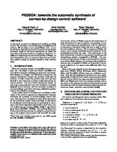
The voltage across the 1KΩ resistance (Vr) is converted to digital values by the ADC and is collected and stored by the microprocessor. This voltage is proportional to the diode current, i.e. Id=(Vr/1KΩ)=Vr x 10-3 A. So the program increments the count and sends the digital data to the DAC which is used as the input voltage for the diode circuit. The voltage across the resistance is converted to digital signal and stored in a memory location of the microprocessor. This goes on in a loop to completely obtain the diodes IV characteristics. The program used to achieve the above objective is available in the arXiv [6]. Figure 3 shows the IV characteristics of a 1N4007 diode measured with the designed interface card. The knee voltage is around 0.7v (indicated by the point where the line intersects ‘X’ axis). The voltage Vd is calculated using Vin and Vr (Vd=Vin-Vr), stored in the microprocessors memory.
V r (volts) (Diode Current in mA)
3.5 3 2.5 2 1.5 1 0.5 0 0
0.5 V d (volts)
1
Fig. 3. The IV characteristics of a p-n diode measured with the designed interface card. (The curve is plotted using data stored in the microprocessor’s memory location using standard plotting software like Curxpt.)
92
A. Dwivedi et al., J. Phys. Stu. 2, 4 90 (2008)
A logical extension now is to evolve this interfacing card to for the parallel port of the personal computer (PC), allowing for easy collection of larger data and then using graphics program for displaying the data etc. We selected the PC’s parallel port since all eight bit output of the ADC can be read simultaneously making the programming simpler as compared to the serial or USB port. Thus, the parallel port presents itself as an inexpensive platform for low frequency data acquisition. Various articles on how to design an interfacing card are available in popular electronics magazines and numerous web sites [711]. In fact a search on the Internet tends to swamp a person with too much information. Here we record our experience of designing and performance of a threadbare design so that the circuit would (i) Be affordable, (ii) Easy to replicate and also (iii) Weeding basic idea from the clutter of information so as to minimize the technical information required to get started. Once the fundamentals are acquired a better design with more complexity can be developed. For this part we have used the ADC0809 chip [12] that is an eight channel ADC i.e. it can convert eight different analog signals depending on which channel is selected. This feature can be used if the experimenter is converting his PC to a dual/multi-channel oscilloscope. The parallel port was developed as a communication port to the printer. Thus, it is referred by the more common and popular name of the “printer port”. The computer sends data to the printer hence early printer ports had very few input pins (only 5). Technically, these ports were called the “Standard Parallel Port” (SPP). Interfacing cards have been made for SPP also [13], however, they require additional hardware and signals for synchronization. Since 1994, parallel ports are bi-directional (PS) allowing eight pins either to act as input or output ports and more importantly these have been made TTL compatible. Parallel ports have further evolved and are presently classified as “Enhanced Parallel Port” (EPP) and “Enhanced Capability Port” (ECP), details of which can be found in Jan Axelson’s book [14]. This project was implemented using the parallel port in the PS mode. Since, Battacharya’s [13] work, a lot has changed as far as the parallel port is concerned and hence we thought it necessary to document our experience. Anyone trying to replicate this project is advised to enter their computer’s BIOS and verify their LPT (that’s how your computer refers to the parallel port) is in PS/ bidirectional mode. While at it, also note the address of the LPT port. This address would be referred as the BASE address throughout the article. The parallel port, visible at the back of your computer, has 25 pins with each pin having a role of its own. Figure 4 shows the pin position and list their grouping and role. Before proceeding to the circuit, we list here some important information of the parallel port. The 25 pins of the parallel port are grouped into Data, Control, Status and ground lines. Colloquially these lines are also called Data, Control and Status ports. The lines are connected to their corresponding registers inside the computer. So by manipulating these registers by programming, one can easily read or write to parallel port using languages like “C” and “BASIC” etc. 1. Data Port (8 pins from 2-9): For example the Data register is connected to Data lines, Control register is connected to control lines and Status register is connected to Status lines. The Data Port or Data Register is simply used for outputting/inputting data on the Parallel Ports’ data lines (Pins 2-9). This register is by default a write only port. If you read from the port, you should get the last byte sent. However if your port is bidirectional, you can receive data on this address. The Base Address shown in the BIOS is the address of the DATA port and in our PC it is 888D (D implies address is in decimal). The STATUS port’s address is BASE+1 (i.e. 889D) and that of the CONTROL port is BASE+2 (890D). Most of the computers list their BASE address in hexadecimal, i.e. 378H, 379H and 37AH for the DATA, STATUS and CONTROL ports respectively. 93
A. Dwivedi et al., J. Phys. Stu. 2, 4 90 (2008)
Fig. 4. The pin layout of a parallel port (PS mode) and their significance.
2. Status Port (5 pins from 10 to 13 & 15): The Status Port is a read only port. Any data written to this port by the programmer for outputting would be ignored. The Status Port is made up of 5 input lines (Pins 0,11,12,13 & 15). Bit 7 of the status register is active low i.e. if bit 7 happens to contain logic 0, there would be +5v at pin 11.
94
A. Dwivedi et al., J. Phys. Stu. 2, 4 90 (2008)
3. Control Port (5 pins 1, 14, 16 & 17): The Control Port was intended as a write port only. When a printer is attached to the Parallel Port, four "controls" are used. These are Strobe, Auto Linefeed, Initialize and Select Printer, except for Initialize all of which are inverted. Since the printer isn’t supposed to send any signal to the computer, default the Control port is an output port. However, the Control port can be programmed to work as an inputs port. Now we are in a position to discuss how to connect the various components required in our circuit and explain it more knowledgeably. We have already stated that the ADC requires a SOC pulse from the computer to start the process of conversion (this of course also synchronizes the two). Since the control port can be used as an output port Bit 3 (of the control port) i.e. pin 17 (of the parallel port) is used for giving Start of Conversion pulse to ADC. Similarly, since the Status Port is an input port, we use it to receive the End of Conversion pulse that would then tell the computer that the ADC has completed the conversion process and the data is available for the Data port to read and save in the computer. Figure 5 pictorially explains the above-mentioned idea. We now briefly discuss how programming generates the SOC.
Fig. 5. Details of using the various ports to handshake with the ADC0809
Generating the SOC Pulse To generate SOC pulse the output of pin Crtl-3 (pin notations explained in fig 4) has to go high (+5v) for a time period greater than 20ns and then return to ground level. Since the output of Crtl-3 is inverted to whatever is written in the third bit of the control register, we give the following instructions (these instructions are of turbo basic, a variant of BASIC) Out 37AH, 0 Delay 0.05 Out 37AH, 8 The Delay command introduces a high pulse of 0.05sec (50ms). Reading the EOC Pulse The ADC gives EOC pulse (signal goes low on completion of conversion) to the parallel port (Status port, pin Status-3). The Status port works as an input port only when Crtl-0 is high. Since output of 95
A. Dwivedi et al., J. Phys. Stu. 2, 4 90 (2008)
Crtl-0 is also inverted, which writing to the control register the Least Significant Bit (LSB) should be made low (bit should be zero). This was invariably the case when for SOC we sent 0 and 8 to the control register. To receive the EOC pulse we read the status port, using the INP command of TB. The syntax is a% = Inp (379H) (1)
Figure 6: Designed PCB on computer and as seen after assembling the circuit. Actual size of the PCB is 9cm x5cm.
Where 379H is status port address and on its execution all the eight bits of the status register is saved in a set variable a%. The third bit is then checked for 1 or 0. A zero implies the arrival of EOC. The ADC0809 is quite a developed chip with (Address Latch Enable) ALE pin for latching the address of the channel selected. ALE signal is essentially a signal of IC8085 for distinguishing between address and data that share the same lines. The signal allows for latching the address even after the lines are taken up by the data. Since we plan to use only a single channel, all the address pins are grounded (Channel 0 is selected) and ALE is tied to SOC. Also, to tri-state the data bus in a complex peripheral circuit, an Output Enable (OE) pin is given. Since we are only using one chip in our circuit, we allow it to demand the bus at all time by keeping OE high by connecting it to Vcc, and (+)Vref pin that are given +5v. (-)Vref is grounded.
96
A. Dwivedi et al., J. Phys. Stu. 2, 4 90 (2008)
Clocks pulses required for the ADC0809 were given by an IC555 in astable mode [9] oscillating at a frequency of 227.27 KHz. The frequency is achieved by selecting proper values of resistances and capacitance for the circuit. The formula used is given as
F=
1 0.693( Ra + 2 Rb )C
(2)
Where Ra and Rb are resistances connected between pin 8–7 and pin 7-6 of IC555 respectively. If we take R=Ra=Rb, then
F=
1 2 RC
(3)
The output lines of ADC0809 (i.e. pins D0-D7) were given to the buffer 74LS244 whose output was connected to the PC’s parallel port by a 25-way-male connector. The buffer chip consists of eight operational amplifiers to who’s input the data bits from ADC are connected and their outputs are connected to the parallel port. Technically the octal buffer 74LS244 is a typical example of tri-state buffer, it also known as a line driver or line receiver amplifying the current at the output. We designed the PCB shown in Figure 6.
Fig. 7. Display of captured data of an input sine wave.
To test the interfacing card, different waveforms were given at the input of ADC0809 from a function generator. Before doing so, we have to be very careful and signal condition the input. That is, make sure that the input waveform’s peak-to-peak voltage in between 0 to +5volts and that it’s frequency is between 1 to 10Hz. For programming, we used Turbo-basic (TB), which is a High-Level Language with English like commands. Our program is available in the arXiv [16]. TB is very elementary and easy to learn. Moreover, TB comes with a library function called MTIMER (micro-timer), which theoretically allows to time events with a 1-microsecond resolution. Using this we can work out the frequency of the 97
A. Dwivedi et al., J. Phys. Stu. 2, 4 90 (2008)
waveform input to our interfacing card. We can also plot the saved data in a voltage versus time graph to get a display similar to that seen on an oscilloscope (see figure 7). However, we found that Mtimer was not a reliable timer in the micro-seconds regime but was working very reliable in the milliseconds regime. This crippled our ability to work with very high frequencies but then ADC0809 can only reliably convert signals below 1000Hz (page 4 of ref 12). Figure 7 is a plot of the data stored as an ASCII file and plotted using the software “Wgnuplot”. While the trend of the sine wave is evident, it was impossible to quantify the wave confidently. That is, one couldn’t comment on Vm or the frequency confidently. For this software “Curxprt” was used for curve fitting. The software returns the best fitting curve, which is shown, as the continuous line in fig 7. It should be noted here that we couldn’t access the PC’s parallel port by user written programs with Microsoft operating systems beyond WINDOWS NT/2000/XP. For systems with these operating systems you either have to develop a driver for your interfacing card or use Visual Basic with supporting “INPUT32.DLL” file for WINDOWS NT/2000/XP. Utilities like “userport.exe” also allow easy access to ports in Win XP. Improvement in this project would involve developing the program further to plot data as it is being recorded. Thus, making the whole project usable to a student only interested in the physics utility of the device. However, our design was successful in teaching us the fundamentals behind interfacing and allowed us to do slow event physics experiments.
Acknowledgement We would like to express our gratitude to the lab staff of S.G.T.B. Khalsa College and also U.G.C. for the assistance (No.F.6-1(25)/2007(MRP/Sc/NRCB)).
References: [1] [2] [3] [4] [5] [6] [7] [8] [9] [10] [11] [12] [13] [14] [15] [16]
Malvino and Leech, Digital Electronics, McGraw Hill 4th Edition (NY, 1986). Terry L. M. Bartelt, Digital Principles: An Integrated Laboratory Approach, Prentice Hall (New Jersey, 2002). M.M. Belekar and S.V. Gogawale, Physics Education 17, 315 (2000). Shruti P. Kavathalkar and C.S. Adgaonkar, Physics Education 15 35 (1998). Ramesh S. Gaonkar, “Microprocessor Architecture, Programming and applications with the 8085/8080A”, Wiley Eastern Limited (India, 1993). Arti Dwivedi and P.Arun “Simple 8085 microprocessor compatible I/O card“, arXiv:physics/0410150v1 [physics.ed-ph]. http://www-server.bcc.ac.uk/~zcapl31/LptADC.html http://www.repairfaq.org/tilipg http://www.access.digex.net/~pha D.N. Kyatanavar, M.S. Patil, G.G. Tengashe and M.S. Deshpande, IEEE Journal of Education, 47 109 (2006). M.M. Vijai Anand, Electronics For You, “PC Based Oscilloscope”, Dec 2002. Datasheet from National Semiconductor (http://www.national.com/ds/DC/ADC0808.pdf). Ravi Bhattacharjee, Chemistry Eduction, 2, 39-50 (1992). Jan Axelson, Parallel Port Complete, Penram International Publishing, 1st Edition (India, 2005). Ramakant A. Gayakwad, Operational Amplifiers and linear integrated Circuits, 4th Edition Prentice Hall India (India, 2002). Sumit Gambhir and P.Arun, “Threadbare Parallel Port DAQ Card”, arXiv:0708.3487v1 [physics.ed-ph]. 98