Proc. of the International Conference on ‘Advances in Mechanical Engineering’, December 15-17, 2008 S.V. National Institute of Technology, Surat – 395 007, Gujarat, India
Performance Evaluation of Edible Oil Drum Filling Machine By Changing Control Devices (Experimental Methods) Patel Narendra K.*, Prof. Dhaval M.Patel**, Parag K. Taktawala***, Dr. J. L. Juneja**** * M.Tech Student, U. V. Patel College of Engineering** Asst. Professor, U. V. Patel College of Engineering, ***Proprietor Zenn Systems, Ahmedabad, ****Principal, U. V. Patel College of Engineering, Kherva, Mehasana. (NG)
[email protected],
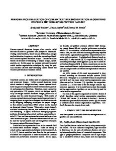
[email protected] Abstract: Today’s requirements for the process industries are improve the performance of the existing systems and operate the plant at optimum level as well as to mitigate the effect of labor shortage. Huge amount of manpower is utilized by process industries which can have only feasible solution that is to make the system automatic. In this paper we have made the effort to automate edible oil drum filing machine. In the way of this effort, first we made automatic drum filling machine for filling of the edible oil drum of the capacity of 15 kg. Initially we are not able to get accuracy in filling of the drum. We have been operated two pneumatically controlled single acting valves for control. We have adopted different options to achieve the accuracy by changing or adding components to accomplish the desired amount of the accuracy. We have performed series of experiments to attain the accuracy and this paper shows all details of experimental setups and results of experiments. To reach the desired amount of accuracy we have used pneumatically operated as well as electrically operated control valves with accessories. We have made the conclusive remarks, which can help to improve the performance of these kind existing process industries. Key Words: Drum Filling Machine, Pneumatic Valves, Solenoids, Load-cell, Filling rate 1. Introduction In this paper we tried to cover the complete route and analysis of the fluid flow in filling Machine. In automatic Drum Filling Machine we have required desired amount of accuracy as well as the oil filling time should be small as much as possible, which will give accurate operation with optimum lead time. In this paper we have included the performance analysis of the piping system by changing the control devices. The piping layout line diagram and model of filling head assembly along with control devices for filling machine are as shown in following Figure.
Figure 1: Piping Layout for Filling Machine
Proc. of the International Conference on ‘Advances in Mechanical Engineering’, December 15-17, 2008 S.V. National Institute of Technology, Surat – 395 007, Gujarat, India
In above diagram the main line of 3” diameter is converted in to 1” with the use of reducer. Then the flow of 1” pipe is controlled by 1” – Pneumatically operated Single acting Angle Type valve. Then the flow is diverted in to two directions for course feed and fine feed. The course feed having same diameter of 1” and the fine feed line is of ½” diameter. The course feed valve is of same 1”- Pneumatically operated single acting angle type valve along with quick release valve for quicker response of the valve. In the line of fine feed ½” – Electrically operated Solenoid valve is placed due to quicker response and better accuracy of the valve. After that both the pipes are merged and placed for the nozzle. 2. Important factors consideration for Drum Filling Machine design Important factors for attaining the high degree of accuracy in Drum Filling Machine ╠ Valves should be placed as nearest as possible to the output nozzle. ╠
Nozzle should be as close as possible to the drum.(Flight time of the oil should be as minimum as possible.)
╠
Constant pressure and constant flow is required as inlet
╠
Bend in the pipe should be as less as possible.
╠
Response time of the valve should be as low as possible.
╠
Dripping after closing the valve should be minimized. In fine feed this thing can be done by taking small diameter pipe, which will result capillary effects and minimize dripping.
3. Experimental Setup The following equipments required for experimental setup (Figure - 2): 1. Filling machine assembly 2. Filling Head Assembly 3. Load Cell Table 4. Controller 5. 1”
–
Operated
Pneumatically Single
acting
Angle type Valve (2 Nos) 6. ½”
-
Operated
Pneumatically Single
acting
Angle type Valve 7. ¼” – Electrically Operated Solenoid Valve 8. Air Compressor Unit along with piping and Fittings 9. Stop Watch Figure 2: 3- Dimensional Experimental Set Up
Proc. of the International Conference on ‘Advances in Mechanical Engineering’, December 15-17, 2008 S.V. National Institute of Technology, Surat – 395 007, Gujarat, India
4. Accuracy Measurement through Experimental Methods: For managing the accuracy with in the tolerance limit we have done experiments on prototype. In this experiment we have been changed the flow control devices in the machine. For controlling the flow of fluid we have been taken for different type of arrangement on the machine and we have been taken experimental readings. According to changing the flow control arrangement four different conditions are as follows: 1. 1” – Pneumatically Operated Angle Type Valve 2. 2 Nos 1” – Pneumatically operated valves are Placed Parallel and ¼” – Solenoid valve placed for fine Feed. 3. 1” and ½” – Pneumatically Operated Valves are Used for Course and Fine Feed. 4. 1”- Pneumatically operated valve for course feed and ¼” – Solenoid valve for fine feed 1. 1” – Pneumatically Operated Angle Type Valve In this condition we have been taken only one valve for control the fluid. That valve is of 1” – Pneumatically operated single acting angle type valve of Airmax India Limited. We have been taken experimental results for that condition. The line diagram is shown in figure 3 as follows:
Figure 3: Condition 1: Piping Layout for Filling Machine We have performed different experiments based on above condition and results are shown in table 1 and efficiency is derived out from that results. Table 1: Experimental Results for Condition 1. Sr No
Filling Weight in kg
Difference
% Accuracy
1
15.164
0.164
98.90%
2
15.122
0.122
99.18%
3
15.084
0.084
99.44%
4
15.170
0.170
98.87%
5
15.112
0.112
99.25%
Proc. of the International Conference on ‘Advances in Mechanical Engineering’, December 15-17, 2008 S.V. National Institute of Technology, Surat – 395 007, Gujarat, India
2. Two 1” – Pneumatically Operated Angle Type Valve and ½” - Pneumatically Operated Angle Type Valve Placed Parallel In this condition we have been taken three parallel valves for control the fluid. Out of that two valves are of 1” – Pneumatically operated single acting angle type valve and third is ½” – Pneumatically operated Single acting angle type valve of Airmax India Limited. We have been taken experimental results for that condition. The line diagram is shown in figure 4 as follows
Figure 4: Condition 2: Piping Layout for Filling Machine We have performed different experiments based on above condition and results are shown in table 2 and efficiency is derived out from that results. Table 2: Experimental Results for Condition 2. Sr No
Filling Weight in kg
Difference
% Accuracy
1
15.200
0.200
98.67%
2
15.125
0.125
99.16%
3
15.080
0.080
99.46%
4
15.175
0.175
98.83%
5
15.100
0.100
99.33%
3. 1” – Pneumatically Operated Angle Type Valve and ½” - Pneumatically Operated Angle Type Valve Placed Parallel In this condition we have been taken two parallel valves for control the fluid. Out of that one valve is of 1” – Pneumatically operated single acting angle type valve and second is ½” – Pneumatically operated Single acting angle type valve of Airmax India Limited. We have been taken experimental results for that condition. The line diagram is shown in figure 5 as follows
Proc. of the International Conference on ‘Advances in Mechanical Engineering’, December 15-17, 2008 S.V. National Institute of Technology, Surat – 395 007, Gujarat, India
Figure 5: Condition 3: Piping Layout for Filling Machine
We have performed different experiments based on above condition and results are shown in table 3 and efficiency is derived out from that results. Table 3: Experimental Results for Condition 3. Sr No
Filling Weight in kg
Difference
% Accuracy
1
15.090
0.090
99.40%
2
15.038
0.038
99.75%
3
15.000
0.000
100%
4
15.038
0.038
99.75%
5
15.040
0.040
99.73%
4. 1” – Pneumatically Operated Angle Type Valve and ¼” – Electrically Operated Solenoid Valve In this condition we have been taken three parallel valves for control the fluid. Out of that two valves are of 1” – Pneumatically operated single acting angle type valve and third is ¼” – Electrically Operated Solenoid type valve of Airmax India Limited. We have been taken experimental results for that condition. The line diagram is shown in figure 6 as follows
Figure 6: Condition 4: Piping Layout for Filling Machine
Proc. of the International Conference on ‘Advances in Mechanical Engineering’, December 15-17, 2008 S.V. National Institute of Technology, Surat – 395 007, Gujarat, India
We have performed different experiments based on above condition and results are shown in table 4 and efficiency is derived out from that results. Table 4: Experimental Results for Condition 4. Sr No
Filling Weight in kg
Difference
% Accuracy
1
15.010
0.010
99.93%
2
15.000
0.000
100%
3
14.996
-0.004
99.97%
4
14.990
-0.010
99.93%
5
15.006
0.006
99.96%
5. Analysis of Results: From all experiments with different conditions, following table shows the comparative analysis of the results taken by experimental methods by taking four different types of fluid control devices: Table 5: Cumulative Experimental Results for All Conditions. Sr No
Experiment 1
Experiment 2
Experiment 3
Experiment 4
1
15.164
15.200
15.090
15.010
2
15.122
15.125
15.038
15.000
3
15.084
15.080
15.000
14.996
4
15.170
15.175
15.038
14.990
5
15.112
15.100
15.040
15.006
Max
15.170
15.200
15.090
15.010
Min
15.084
15.080
15.000
14.990
Difference
0.086
0.120
0.090
0.020
The above tabulated results can also be deduced graphically as bellow.
Accuracy Analysis
Fluid Filled
15.3 15.2
Experiment-1
15.1 Experiment-2
15 14.9
Experiment-3
14.8 1
2
3
4
Experiment No
5
Experiment-4
Proc. of the International Conference on ‘Advances in Mechanical Engineering’, December 15-17, 2008 S.V. National Institute of Technology, Surat – 395 007, Gujarat, India
The above graph shows that the results in the experiment no 4 are accurate as well as consistent compare to other three experiments. The deviation in the results is minimum in last experiments. So by changing the control devices the 4th option is optimum and suitable for the filling of drum with better accuracy. References:
[1]. User Manual of Automatic can-filling machinery (PIGMENT AND RESIN [2]. [3]. [4]. [5]. [6]. [7]. [8].
TECHNOLOGY, Emerald 1973) Arun K. Paul, J. K. Mishra. and M. G. Radke, Reduced Order Sliding Mode Control for Pneumatic Actuator at Conference on Robotics and Automation (IEEE1994) D. Ben-Dov and S. E. Salcudean, A Force - Controlled Pneumatic Actuator, at Conference on Robotics and Automation, IEEE 1995 Robert van and Gary M. Bone, Accurate Position Control of a Pneumatic Actuator Using On/Off Solenoid Valves, at Conference on Robotics and Automation (IEEE 1997) User Manual, “Airmax India Limited, Ahmedabad” So-Nam Yun', Young-Bog Ham, Jung-Ho Park, Pressure Regulator for Pneumatic Valve, SICE-ICASE International Joint Conference, IEEE 2006) www.fillers.com www.universalfilling.com