Overlay Method and Knowledge Evaluation Using Fuzzy Logic Branko Žitko Faculty of Natural Sciences, Mathematics and Education Nikole Tesle 12, 21000 Split, Croatia
[email protected]
Abstract. E-learning took place between information and communication technology on one side and education on the other. Authoring shells are kind of e-learning systems capable for generating intelligent tutoring systems. These systems usually models learner’s knowledge by using overlay method during tests. In this paper is presented an advanced approach in refining and making flexible mark of learner’s knowledge by applying fuzzy system in overlay method.
Introduction Information and communication technology (ICT) became inseparable part of educational systems that helps teachers during class lectures or replace the same combining numerous methods and way of realizing learning and teaching process. Application of technology and development of educational systems are in support of e-learning paradigm that today comprise not only intelligent e-learning systems, but also other medias like CD-ROM, CAI, video conferencing, satellite distribution of learning materials and virtual knowledge networks. Today, development on e-learning field is heading for designing Learning Management System (LMS) [1] and Intelligent Tutoring System (ITS) [2]. In a difference of LMS’s that mainly distribute electronically content on learner’s request, ITS’s implements intelligence in a several segments of learning and teaching process realization. Generally, ITS is a system based on several knowledge representation technologies. Knowledge representation in ITS not only incorporate student’s knowledge, but also and domain knowledge that learner uses during knowledge creation in purpose of teaching. Mentioned knowledge kinds have designated ITS’s modular system architecture [3] containing: • Expert module – for designing domain knowledge, • Teacher module – for designing teaching content, • Learner module – for storing information of user’s progress on a chosen domain knowledge and • Communication module – that interconnects all modules and system users.
Learner module provide main learning and teaching functions and comprises testing of the learner’s knowledge following by generating mark and recommendations for the further work. In this paper is described one of the methods for testing and evaluating learner’s knowledge that is implemented in Tutor-Expert system (TEx-Sys) [4]. TEx-Sys is defined as intelligent hypermedial authoring shell that means it is an instance of intelligent authoring shells (IAS) and serves as ITS generator. Domain knowledge representation in TEx-Sys system is based on semantic network with frames technology [5]. TEx-Sys implements two methods of knowledge evaluation. Quiz method [6] dynamically generate questions and answers over a set of nodes and links in semantic network with frames laying as a base for domain knowledge. The other is overlay method that uses domain knowledge as a source for generating problem knowledge. Used knowledge in the generated problem, learner tries to expand as close as possible to the original domain knowledge. Results of difference analysis between mentioned knowledge provide input for calculating mark of the test. Knowledge overlay technique looks at the differences between learner and teacher, enabling wrong knowledge assumptions as well as misconceptions. For that purpose three knowledge bases are compared: • {Expert} knowledge base containing expert’s knowledge in chosen domain, • {Problem} knowledge base having generated test set of nodes and links, • {Solution} knowledge base containing solution to the problem. These knowledge bases are realized using semantic network with frames technique [7]. When learner runs testing module he is offered by three types of tests: • Test 1: All links are removed from chosen domain knowledge. Learner has to input missing links • Test 2: Fragment of knowledge is generated with having not less than 30% and not more than 70% of original nodes in chosen domain knowledge. Learner has to fulfill given knowledge with missing nodes and their connections. • Test 3: Fragment of knowledge is generated with having not less than 50% of the nodes and some of nodes are wrongly connected. Learner has to find wrongly connected nodes and fulfill given knowledge with missing nodes. Choosing type of the test takes {Expert} knowledge base and, by removing nodes, removing and/or wrongly connecting nodes, generates {Problem} base. During solving of this knowledge base learner can remove nodes, add missing nodes and add new nodes that are not in {Expert} knowledge base. With links are following treatments: adding new connections, removing correct connection, removing wrong connection, adding correct connection, adding wrong connection and adding missing connection. These actions over nodes and connections define their status. Overlaying nodes and connections in {Expert}, {Problem} and {Solution} knowledge bases completes reconstruction of tracing learner’s during creation of the solution. TEx-Sys has elaborated qualitative criterions of evaluation based on numeric and descriptive qualifications and is depended on knowledge representation technique and on performed actions over elements of semantic network formalized in the knowledge base. Separated quantification of nodes and links in semantic network defines criterions for node’s and link’s scores. These criterions are very strict and not flexible
in generating student’s mark. By determining weighting factor for elements of semantic network we try to make some elements more important than the other. The other step in making flexible knowledge mark uses fuzzy system. In following is described such a procedure.
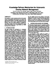
Weighting Factor in Semantic Network with Frames Elements of semantic network with frames are nodes, links, properties and property values in frames. Actions of adding, updating or deleting some element of semantic network with frames will imply on overall number of points for that element. For example, if correct node is added into semantic network with frames, then overall number of points for nodes is increased by weight factor of that node. Then score for nodes will be the scale between sum-total score for nodes and sum-total maximal score for nodes which is equal to sum of all node’s weight factor in domain knowledge. Weight Factor for Nodes Problem of defining weight factor for elements of semantic network with frames will be explained on nodes example. Semantic network is abstracted by directional graphs where the node is vertex and the link between two nodes is arc. Directional graph G is ordered triplet (V, E, I) where V is set of vertices, E set of edges, and I set incidences containing triplets (vi, e, vj) where vj is tail of edge e and vi is its head. Vertex vj is a child in relation to vi, i.e. vertex vi is a parent to vj via edge e. Weight factor of vertices are determined by their position in directed graph. Generally looking, parent vertices have larger weight factor then their child vertices. On figure 1 vertices v1 and v2 have larger weight factor then v5 and v6 because they do not have parents, relative to v5 and v6 having no child. Vertices v3 and v4 have children and parents, thus having larger weight factor then v5 and v6 and smaller weight factor then v1 and v2. Though, vertex v3 is "weightier" then v4 because he is parent of v4.
Fig. 1. Subgraphs of directed graph
Directed graph on figure 1 contains two sub-graphs G1=(V1, E, I1) and G2=(V2, E, I2) containing disjunctive sets I1 and I2 whose union is incidence set of graph G. Same
assumption goes to the sets V1 and V2, relatively V1 ∩ V2 = ∅ and V1 ∪ V2 = V . Weight factor of directed graph’s vertex is determined by overall count of parents in mediated and intermediated relation to all other vertices in directed graph. In case of two vertices having equal number of parents in relation to all other vertices, the one with more mediated or intermediated children is having larger weight factor. Determination of weight factor for graph G vertices starts with implementation of incidence matrix. (i, j) element of the incidence matrix M(G) for directed graph G is determined by counting number of connections between vertices vj and vi. For each incidence matrix M(G) is defined matrix M’(G) whose elements are equal to elements of M(G) except diagonal elements which are set to zero.
⎡0 ⎢0 ⎢ ⎢0 M (G ) = ⎢ ⎢0 ⎢0 ⎢ ⎢⎣0
0 1 0 0 0⎤ 0 1 0 0 0⎥⎥ 0 1 1 0 1⎥ ⎥ 0 0 0 1 0⎥ 0 0 0 0 0⎥ ⎥ 0 0 0 0 0⎥⎦
Fig. 2. Example of incidence matrix
For vertex vi in directed graph G on base of M’(G) matrix can be attached pair (pi, ci) where pi is number of parents, and ci number of children for vertex vi. Now it is natural to define function fm which will calculate number of children for vertex vi by summating elements in i-th row of matrix M’(G)m, and summating elements of i-th column of matrix M’(G)m. (1)
f m : V → N0 × N0 f m ( vi ) = ( pi m , ci m ) n
n
k =1
k =1
p m i = ∑ ak ,i , ci m = ∑ ai ,k M '(G ) = ⎡⎣ ai , j ⎤⎦ n=V m
By the function (1) diagonal elements of M(G) matrix are not summated because these elements tells that vertex is simultaneously parent and child to itself. This
function gives us for each vertex overall number of parents and children in immediate connection with other elements of directed graph G. By appliance of function (1) we have following results in (2): (2)
f 1 (v1 ) = (0,1) f 1 (v2 ) = (0,1) f 1 (v3 ) = (2,2) f 1 (v4 ) = (1,1) f 1 (v5 ) = (1,0) f 1 (v6 ) = (1,0)
If M’(G)2 is calculated, then each vertex of directed graph will have number of parents and children in intermediate connection counted by the second level of incidence. For example, vertices v1 and v2 have children v4 and v6, while v3 has v5 as intermediate child. Other vertices do not have intermediate children. Function f2 will for each vertex attach ordered pair by matrix M’(G)2.
⎡0 ⎢0 ⎢ ⎢0 M ' (G ) 2 = ⎢ ⎢0 ⎢0 ⎢ ⎣⎢0
f 2 (v1 ) = (0,2)
0 0 1 0 1⎤ 0 0 1 0 1⎥⎥ 0 0 0 1 0⎥ ⎥ 0 0 0 0 0⎥ 0 0 0 0 0⎥ ⎥ 0 0 0 0 0⎦⎥
f 2 (v2 ) = (0,2) f 2 (v3 ) = (0,1) f 2 (v4 ) = (2,0) f 2 (v5 ) = (1,0) f 2 (v6 ) = (2,0)
Fig. 3. Second level of incidence in graph G
After getting null-matrix as result of powering M’(G) matrix, we can define function F which will for each vertex vi attach ordered triplet (pi, ci, ri) where pi and ci are total number of parents and children for vi, while ri is number of round connections (cycles) for vi. m −1
(3)
m −1
F (vi ) = (∑ pi , ∑ ci k , ri ) k
k =1
{
k =1
}
m = min n ∈ N : M '(G ) n = [ 0] ci = ai ,i , M (G ) = ⎡⎣ ai , j ⎤⎦
If we put in order results of function fi for each vertex in directed graph G we will have table 1.
Table 1. Vertices and results of function fi
v1 v2 v3 v4 v5 v6
f1 (0,1) (0,1) (2,2) (1,1) (1,0) (1,0)
f2 (0,2) (0,2) (0,1) (2,0) (1,0) (2,0)
f3 (0,1) (0,1) (0,0) (0,0) (2,0) (0,0)
F (0,4,0) (0,4,0) (2,3,1) (3,1,0) (4,0,0) (3,0,0)
More important are those vertices having less number of parents. If two vertices have the same number of parents than more important would be the one having greater number of children. In case of two vertices having equal number of parents and equal number of children, than more important one would have greater number of cycles. By this principle, vertices v1 and v2 are the most important and have the same weight factor. Next important vertex is v3. Vertices v4 and v6 have equal number of parents, but v4 is more important because having one child. If we sort ascending results of F function for each vertex than we will have sequence: (4,0,0) , (3,0,0) , (3,1,0) , (2,3,1), (0,4,0) (4) This sequence has 5 elements and by dividing index of the element with overall number of elements in sequence, we will calculate weight factor for each element in sequence. The least weight factor has v5 while v1 and v2 have weight factor equal to 1, which is also maximal value for the weight factor.
Fig. 4. Weight factors for vertices in graph G
After determination of weight factor for vertices in directed graph, weight factor for edge is calculated as average of weight factors for vertices on that edge. Figure 5 shows that edges having tail in v3 will have weight factor 7 and 3 . 10
5
Fig. 5. Weight factor for edges in graph G
Weight factor of properties in frame of generic node will depend on weight factor of node having that frame. For example, if the weight factor of generic node is k and that node has a frame with m properties, than weight factor for each property in this node’s frame will be k . On the same principle is calculated the weight factor for m
property values in frames of individual nodes. Obviously there is a bijection between graph’s vertices and nodes in semantic network, as well as graph’s edges and node’s connections. This bijection translate weight factor of vertices and edges into weight factor of nodes and connections.
Fuzzy-Logic Appliance in Knowledge Evaluation Student’s knowledge evaluation can be generally described using fuzzy system [8] having uncertain input vector and certain output scalar as a presentation of student knowledge mark. Input variable in fuzzy system for determining mark of the knowledge is 4dimensional uncertain vector. Every element of this vector represents achieved scores for specific semantic network with frames element kinds. Conversion from uncertain to certain is practiced by membership functions. Membership degrees are going to be calculated using center to maximum method. Output value of the fuzzy system is knowledge evaluation mark. Score for semantic network with frames elements will be proportion of weight factor in solution base with a sum of weight factor for nodes in expert and problem bases. We will define weight functions V(base, element) where base parameter can be problem, solution or expert, while element parameter can be node, link, property or property value. Weight function for specific base and specific semantic network with frames element is a sum of all weight factors for specific kind of element. For example, V(problem, node) is sum of weight factor of all nodes in problem base.
Table 2. Certain vector determination by using importance function
Element
Node Link Property Property Value
Knowledge bases Problem Solution Expert 3.4 4.1 6.2 4.4 5.2 8.7 2.9 4.4 4.9 3.2 5.1 5.3
Score
Certain Vector (0.87, 0.55, 0.75, 0.90)
0.87 0.55 0.75 0.90
1 0,9 0,8 0,7 0,6 0,5 0,4 0,3 0,2 0,1 0
Membership
Membership
It is naturally to define function Score(element) as a ratio of difference V(solution, element) – V(problem, element) with difference V(expert, element) – V(problem, element). In table 2 is given example for determining certain vector by weighting elements of semantic network with frames in expert, problem and solution knowledge bases. In case to facilitate difference between importance between expert and problem knowledge bases for a given element of semantic node with framework, than score for that element is not taken in certain vector, thus vector’s dimension is decreased. Each dimension of certain vector has defined membership function. Determination of these functions is intuitive and is based on experience. Usually, scores for nodes and links are more important than other elements. On figure 6 are given membership functions for all element kinds of semantic network with frames.
0
0,1 0,2 0,3 0,4 0,5 0,6 0,7 0,8 0,9
1 0,9 0,8 0,7 0,6 0,5 0,4 0,3 0,2 0,1 0
1
0
0,1 0,2 0,3 0,4 0,5 0,6 0,7 0,8 0,9
1
Score(Link)
1
1 0,9 0,8 0,7 0,6 0,5 0,4 0,3 0,2 0,1 0
0,9 0,8 0,7 Membership
Membership
Score(Node)
0,6 0,5 0,4 0,3 0,2 0,1
0
0,1 0,2 0,3 0,4 0,5 0,6 0,7 0,8 0,9 Score(Property)
1
0 0
0,1
0,2
0,3
0,4
0,5
0,6
0,7
0,8
0,9
1
Score(Value)
Fig. 6. Membership function for each element of semantic network with frames
If we look on a membership function results for scores of semantic network with frames exampled in table 2, then we would get uncertain values as shown in a table 3.
Table 3. Uncertain values example determined by membership functions Node 0.87 0.96
Score Membership
Link 0.55 0.61
Property 0.75 0.42
Value 0.90 0.67
By fuzzy reasoning uncertain membership function’s values for semantic network with frames element scores are numbers between 0 and 1. Simple rule for determining that uncertain number is absolute value of membership function’s values. Graphically result is displayed as a weight of geometric figure whose vertices are defined by coordinates of certain and uncertain value of membership function, as on figure 7. 1 0,9 0,8 0,7
Node
0,6
Link
0,5
Property
0,4
Value
0,3 0,2 0,1 0 0
0,1
0,2
0,3
0,4
0,5
0,6
0,7
0,8
0,9
1
Fig. 7. Method for determining uncertain mark
Output and certain vector of this fuzzy system is a mark of learner’s knowledge. It is important to define function that for each uncertain number trace concrete number. Similar as membership function, this function is also based on experience. Example of this function is given in figure 8. 10 9 8
Mark
7 6 5 4 3 2 1 0 0
0,1
0,2
0,3
0,4
0,5
0,6
0,7
0,8
Fuzzy mark
Fig. 8. Determining knowledge mark as function of uncertain mark
0,9
1
Conclusion Intelligent Tutoring Systems can have different methods for knowledge evaluations. Applying fuzzy system is regularly choice because of its functionality similar to human process of reasoning. Knowledge mark, as result of approximate human consideration is hardly explainable on precise and procedural way. Fuzzy systems give acceptable and flexible reasoning methods, but sacrifice precision and correctness. One of the main problems during development of fuzzy systems is comprehensible presentation of fuzzy rules and membership functions. Often is necessary to synchronize fuzzy rules with membership function resulting in satisfying results. One of the solutions is employment of machine learning methods that would improve fuzzy rules and membership functions.
References 1. Brandon Hall: Learning Management Systems 2001: How to Choose the Right System for Your Organization, brandon-hall.com (2000). 2. P. Brusilovsky, E. Schwarz, G. Weber: "An intelligent tutoring system on World Wide Web", in Frasson, C., Gauthier, G., Lesgold, A., editors, Intelligent Tutoring Systems, Vol. 1086 of Lecture Notes in Computer Science, Berlin, Germany (1996) pp. 261-269, 3. Burns, H. L., Capps, C. G.: Foundations of intelligent tutoring systems: an introduction, Poison, M.C., Richardson, J. J. (Ed.) Foundations of intelligent tutoring systems, Lawrence Eribaum, London, (1988) 1-19 4. Stankov, S.: Isomorphic Model of the System as the Basis of Teaching Control Principles in an Intelligent Tutoring System, PhD Diss, Faculty of Electrical Engineering, Mechanical Engineering and Naval Architecture, University of Split, Split, Croatia, (in Croatian) (1997) 5. Quillian, M.R.: Semantic memory, in Minsky, M. (ed.), Semantic Information Processing, MIT Press (1968) 6. Rosić, M: Establishing of Distance Education Systems within the Information Infrastructure, M.Sc.Thesis, Faculty of Electrical Engineering and Computing, University of Zagreb, Zagreb, Croatia (in Croatian) (2000) 7. Stankov, S., Glavinić, V., Rosić, M.: On Knowledge Representation in an Intelligent Tutoring System, Proc. 4th IEEE International Conference on Intelligent Engineering Systems 2000 – INES'2000, Portorož, Slovenia, September 17-19 (2000) pp. 381-384 8. Passino, K. M., Yurkovich, S.: Fuzzy Control, Addison Wesley Longman, Menlo Park, CA (1998)