Opportunistic Underlay Transmission in Multi-carrier Cognitive Radio Systems Kyuho Son, Bang Chul Jung∗, Song Chong and Dan Keun Sung School of Electrical Engineering and Computer Science, KAIST ∗KAIST Institute for Information Technology Convergence E-mail:
[email protected],
[email protected], {song, dksung}@ee.kaist.ac.kr Abstract— Underlay transmission in cognitive radio enables a secondary (unlicensed) system to utilize a frequency band of primary (licensed) system as long as the unlicensee interferes less than a certain threshold with the licensee. The secondary system needs to carefully consider not only its own channel to achieve a capacity gain by this sharing spectrum in multicarrier systems, but also the interference channel to reduce interference at the primary receiver. In this paper, we formulate a capacity maximization problem of the secondary system under an interference-power constraint as well as a conventional transmitpower constraint, and propose an optimal power allocation policy in which we exploit a two-dimensional frequency-selectivity on both channels. Through extensive simulations, we compare the performance of optimal power allocation policy with that of equal power allocation policy and further investigate the effect of the primary’s power allocation policy on the performance of the secondary system. Numerical results show that the optimal power allocation policy can achieve a higher capacity in more frequencyselective channels, compared to an equal power allocation policy. Interestingly, a water-filling policy for the primary system also gives additional opportunities to the secondary system than the equal power allocation policy.
I. I NTRODUCTION With the emergence of diverse wireless systems and the rapid growth of demanding applications such as multimedia services, a demand for wide spectrum has been increased in recent years and is expected to grow even more in future wireless systems. The traditional approach managing the spectrum (inherently a limited natural resource) is to exclusively allocate the frequency band to different multiple wireless systems/operators. This is usually regulated by the government agencies such as the Federal Communications Commission (FCC) in the United States. The recent FCC measurements [1] have indicated that a large portion of each allocated spectrum is unused or lightly used in general. Therefore, efficient spectrum usage has become a very important issue and has attracted many researchers. In order to better utilize the licensed spectrum, the FCC has launched a Secondary Markets Initiatives [2] whose goal is to remove regulatory barriers and facilitate the development of secondary markets in spectrum usage rights. This proposal introduced a new concept of dynamic spectrum licensing which implicitly requires the use of cognitive radio. And IEEE 802.22 activity This research was supported by the Ministry of Knowledge Economy, Korea, under the ITRC (Information Technology Research Center) support program supervised by the IITA (Institute of Information Technology Advancement) (IITA-2008-C1090-0801-0037).
is the first worldwide effort to define a standardized cognitive wireless regional area network for the opportunistic use of television bands [3], [4]. Cognitive radio (CR), a term first introduced by Mitola [5], is a flexible and intelligent wireless system that is aware of its surrounding environment. The secondary system will benefit from this CR to utilize the licensed band of the primary system as long as the licensee’s operation is not compromised [6]. Based on how not to affect the primary system, transmission modes are classified into three types: interweave, overlay and underlay modes [7]. In the interweave mode, the secondary system can occupy the unused license band, i.e., the spectrum hole, because the majority of the spectrum is typically under-utilized. These spectrum holes change with time and geographic location. Therefore, the secondary transmitter in this mode needs to have the real-time functionality for monitoring spectrum and detecting the spectrum hole. Several spectrum-sensing techniques [8], [9] are proposed and spectrum-sharing techniques mainly based on game-theory have been analyzed [10], [11]. Overlay mode allows the secondary system to use the license band even if the primary system is using the band. The secondary transmitter is assumed to have knowledge of the primary message. The secondary transmitter may use this knowledge to mitigate the interference seen by its receiver using dirty paper coding and/or to relay the primary signal to compensate the SNR at the primary receiver. Devroye et al. [12] proposed a genie-aided cognitive radio channel model and derived the fundamental information-theoretical limits of the gain in this mode. In the underlay mode, simultaneous transmissions of primary and secondary systems are also allowed on condition that the secondary system interferes less than a certain threshold with the primary system. Accordingly, the concept of interference-temperature has been introduced to determine a tolerable interference level at the primary receiver. Ghasemi et al. [13] analyzed the capacity of a secondary user under a received power constraint at the primary receiver in fading environments. However, in practice, the transmit power is limited by the hardware capabilities and safety requirements. Therefore, the transmit-power constraint is needed to be considered together. On the other hand, most next generation wireless communication systems are likely to use orthogonal frequency division multiplexing (OFDM) scheme due to its robustness to multi-path fading and flexibility in resource allocation.
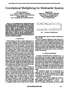
While the underlay mode is usually associated with UWB (ultra wide band) and spread spectrum technologies, there are a few recent literatures [9], [14] considering OFDM as a physical layer technique. The authors in [9], [14] focus on the interweave mode. Once they identify the idle status (availability) of subcarriers, the resource allocation problem is almost the same as the conventional problem with available subcarriers. However, in the underlay mode, the resource allocation problem is completely different due to the simultaneous transmissions of primary and secondary systems. In this paper, we only focus on this underlay mode in the OFDM-based multi-carrier CR systems and investigate the system capacity gain obtained by this underlay transmission. In general, to achieve a higher system capacity, the secondary transmitter needs to opportunistically allocate more power to stronger subcarriers in its own channel, and less or even no power to weaker ones. On the other hand, in order to reduce interference at the primary receiver, the secondary transmitter may allocate more power to deep fading subcarriers in its interference channel (from the secondary transmitter to the primary receiver), and less or even no power to stronger ones. To efficiently compromise these two goals while exploiting the two-dimensional opportunism of frequency-selectivity, we propose an optimal power allocation policy of the secondary system which carefully considers both its own channel and the interference channel. The remainder of this paper is organized as follows. In Section II, we provide a CR system model. In Section III, we introduce our objective and constraints, and propose the optimal power allocation policy. In Section IV, we verify our power allocation through extensive simulations. In Section V, we extend results to the scenario having multiple primary and/or secondary receivers. Finally, we summarize the main observations of this paper. II. S YSTEM M ODEL We consider a CR system with a pair of primary transmitter and receiver and a pair of secondary transmitter and receiver, as shown in Fig. 1. The extension to multiple primary and/or secondary receivers will be discussed later on. We assume that both the primary and the secondary systems are OFDMbased multi-carrier systems using the same bandwidth for their transmissions. f Let gij denote the channel gain from transmitter i to receiver j on subcarrier f , and pfi denote the power allocated to the subcarrier f of transmitter i. The frequency-selective fading channels from a secondary transmitter to both the f f secondary and primary receivers, g22 and g21 , are assumed to be perfectly known at the secondary transmitter. Prior to the power allocation of the secondary system, the primary system allocates power regardless of the secondary’s operation. Hence, the secondary system is able to measure the amount of interference on each subcarrier from the primary transmitter f f f g12 p1 rather than individually knowing the channel g12 and f the power allocation p1 . f Measuring the inter-system channel gain g21 is not so easy f as the intra-system channel gain g22 , but possible by peri-
Primary system
TX1
p1f
p2f
RX1
g11f
g12f g 21f
g 22f
Secondary system
TX2
Fig. 1.
RX2
A CR system model
odically sensing the reverse link transmission of the primary receiver. For example, suppose that the primary system is IEEE 802.16e system operating in time division duplex (TDD) mode, i.e., the primary transmitter is a base station (BS) and the primary receiver a mobile station (MS), respectively. The MS transmits channel sounding waveforms on the uplink (MS-to-BS) to enable the BS to determine the BS-to-MS channel gain under the assumption of TDD reciprocity [15]. The secondary transmitter can also hear this uplink channel sounding signal and measure the channel gain between the MS (the primary receiver) and the secondary transmitter in a similar way. Even though the above method is not applicable in practice, our results still provide the upper-bound performance in multi-carrier underlay CR systems. III. O PTIMAL POWER ALLOCATION POLICY A. Our objective and constrains We present an objective function with constraints for our optimization problem. Our objective is to maximize the channel capacity of the secondary system operating at the same band with the primary system: Ã ! F f f X g22 p2 B log 1 + f f , (1) max p2 F g12 p1 + nf f =1
where the bold letter p2 = [pf2 , f = 1, 2, · · · , F ] is used for vector notation, nf is the noise power on subcarrier f , and B and F denote the system bandwidth and the total number of subcarriers, respectively. There are two constraints on the power allocation. The first one is a transmit-power constraint at the secondary transmitter which ensures the summation of power allocated over all subcarriers is within a power budget Pmax of the secondary transmitter. • Transmit-power constraint: F X
f =1
pf2 ≤ Pmax .
(2)
The second one is an interference-power (receive-power) constraint at the primary receiver which ensures the amount of interference induced by the secondary transmitter is less than a certain threshold. As the interference-power constraints, we deal with two types of constraints: the peak or the average interference-power constraints.
Interference-power constraints: f f f peak: g21 p2 ≤ Imax , ∀f, average:
F 1 X f f g21 p2 ≤ Imax , F
water-level
power
•
(3) (4)
p3 1
B. Capacity maximization problem under total transmit-power and peak interference-power constraints: [P1] We start from a capacity maximization problem [P1] under the total transmit-power and the peak interference-power constraints. F ´ ³ X (5) [P1] max log 1 + g2f pf subject to
f =1 F X
pf ≤ Pmax ,
f =1 g1f pf
p4
p2
f where Imax and Imax are the peak and the average interference temperature level that the primary receiver can tolerate at each subcarrier f and over all subcarriers, respectively. The constraint (3) ensures that the amount of the interference received by the primary receiver at each subcarrier f is less f than Imax and the constraint (4) ensures that the average amount of the interference received by the primary receiver over all subcarriers is less than Imax . The basic notion of the constraint (4) is that even though there are large interference in some subcarriers, small interference in the other subcarriers can compensate the performance of primary system in an average sense. If the primary channel is pretty good, i.e., the bandwidth efficient region, then the primary system can tolerate interference to a certain extent. Otherwise in the power efficient region, however, small interference can deteriorate the performance of the primary system much. Therefore, one could also adapt the interference temperature level according to the channel state of the primary system. To adaptively change the value f of Imax and Imax , channel state information for the primary system is necessary. On the same assumption in Section II (IEEE 802.16e), the secondary transmitter can listen the MAP message from the primary transmitter (BS) and estimate the coarse channel state based on the MCS (modulation and coding scheme) level of the primary transmission. In this paper, however, we assume that the interference temperature level is given/fixed in a conservative manner, and known at the secondary transmitter. We only focus on the optimal power allocation policy for the secondary system for a given and fixed f Imax and Imax . The adaptation of the interference temperature level is beyond the scope of this paper and we leave it as a . . f gf future study. As of now, we denote g2f = gf pf22+nf , g1f = g21 12 1 2 . and pf2 = pf , use log instead of log2 , and drop B/F for simplicity of notations
(6)
f ≤ Imax , f = 1, 2, · · · , F, (7)
This problem is a convex optimization problem [16] because a concave function is to be maximized over a convex constraint
p
1 g 12
Fig. 2.
O
p5
f =1
p≥0
1 p6
1 g 22
1 g 24
1 g 23
1 g 26
1 g 25
1 g 27
subchannel
The graphical interpretation of constrained water-filling
set and, thus, a unique global solution exists. In [P1], constraint (7), which limits the maximum allowable transmit power on f /g1f , is additionally introduced to the the subchannel f to Imax classical water-filling problem. Therefore, we can easily obtain the following optimal power allocation policy p = [pf , f = 1, 2, · · · , F ] for [P1], so called constrained water-filling1 : f " #Imax /g1f 1 1 f p = , f = 1, 2, · · · , F. (8) − λ g2f 0
. where = min [max [a, z] , b]; λ is a non-negative Lagrange multiplier associated with the total transmit-power constraint . PF (6) and is chosen such that a function h(λ) = pf (λ) − f =1 i h f PF Imax is equal to zero. Fig. 2 shows the min Pmax , f =1 gf 1 graphical interpretation of the constrained water-filling. Note that the maximum allowable transmit power on each subchannel is represented as a dotted rectangular box2 . In order to obtain the solution in (8), we can use an iterative algorithm based on a gradient method which starts from an initial waterlevel λ, and increases (or decreases) λ with a small step-size if h(λ) is greater (or less) than zero until reaching close enough to the optimal solution. b [z]a
C. Capacity maximization problem under total transmit-power and average interference-power constraints: [P2] Now we consider a capacity maximization problem [P2] by replacing the peak interference-power constraint with the average interference-power constraint. [P2]
max p≥0
subject to
F X
f =1 F X
f =1
³ ´ log 1 + g2f pf pf ≤ Pmax ,
F 1 X f f g1 p ≤ Imax , F
(9)
(10)
(11)
f =1
This problem is also a convex optimization problem, and, thus, a unique global solution exists. The optimal power allocation 1 Note that some literatures [17], [18] obtain a similar result in a different problem setting. 2 For simplicity of presentation, we sort the inverse of channel gain 1/g f 2 in ascending order in Fig. 2.
policy p for [P2] can be obtained as the following modified water-filling: " #+ 1 1 pf = , f = 1, 2, · · · , F. (12) − λ + g1f µ g2f + . where [z] = max [z, 0]; λ and µ are a non-negative Lagrange multipliers associated with the total transmit-power constraint (10) and the average interference-power constraint (11), respectively. Based on whether the constraint (10) and/or the constraint (11) are active, we can classify the solution into three cases as follows: 1) Power-limited case h i (λ > 0 and µ = 0):
Algorithm 1 Optimal Power Allocation for [P2] 1: Power-limited case
WaterFilling ({g2f }, Pmax ). If < Imax , then go to STEP 4. 2: Interference-limited case – (e p, µI ) = WaterFilling ({g2f /g1f }, F · Imax ). If PF f PF f f f f =1 p /g1 < Pmax , then go to STEP 4. f =1 p = 3: Both-limited case – Set µmin = 0 and µmax = µI . – Repeat until µmax − µmin ≤ ǫ, where ǫ is a small positive constant which controls the algorithm accuracy. 1 • Set µ = 2 (µmax + µmin ) and find ind the minimum – (p, λP ) 1 F
+
pf = λ1 − g1f , ∀f , where λ is chosen such that 2 the transmit-power constraint (10) holds with equality, PF f p = P . This case is exactly the same as the max f =1 classical water-filling solution. 2) Interference-limited i case (λ = 0 and µ > 0): h +
, ∀f , where µ is chosen such that pf = gf1µ − g1f 1 2 interference-power constraint (11) holds with equality, PF f f 1 g p = I . Using the change of variable max f =1 1 F f f f f p = g1 p , ∀f , this case also can be converted into h f i+ f = 1 − g1 , ∀f , the classical water-filling solution. pf µ g2f PF f where µ is chosen such that pf = F · Imax . f =1
3) Both-limited case (λ i> 0 and µ > 0): h + , ∀f , where λ and µ are chopf = λ+g1 f µ − g1f 1 2 sen hold with equality, PF suchf that the both1 constraints PF f f p = P and g p = Imax . max 1 f =1 f =1 F
We propose an optimal power allocation for [P2] in Algorithm 1. Actually, we can find the optimal power allocation by running only the STEP 3 with arbitrary initial values (λ, µ) in Algorithm 1. However, in general, finding an optimal power allocation in the both-limited case requires higher computational complexity than for the conventional waterfilling algorithm because we need to determine Lagrange multipliers (λ, µ) in 2-dimensional space. Besides, the optimal solution mostly falls on the power-limited or the interferencelimited case rather than the both-limited case. Therefore, our algorithm first checks whether the optimal solution belongs to the power-limited or the interference-limited case. In either case, we can use the fast conventional water-filling algorithm [19] to obtain the solution. If neither case meets the optimality condition, then we can infer that the optimal solution occurs at the both-limited case. With the help of the following lemma, Lagrange multipliers (λP , µI ) obtained from STEP 1 and 2 can reduce the search space and speed-up the STEP 3. Lemma 3.1: If the solution of [P2] is in the both-limited case, then the optimal Lagrange multipliers λ and µ are always less than or equal to λP and µI , respectively: λ ≤ λP and µ ≤ µI ,
(13)
where λP and µI are the Lagrange multipliers obtained by assuming the solution is in the power-limited and interferencelimited cases, respectively.
=
PF
f f f =1 g1 p
λ ∈ [0, λP ] satisfying
PF
f =1
·
1 λ+g1f µ
−
1 g2f
¸+
= Pmax .
Obtain power vector p by putting λ and µ into (12). P f f If F1 F f =1 g1 p ≤ Imax , then µmax = µ; otherwise, µmin = µ. 4: FINISH: (λ, µ) are the optimal Lagrange multipliers and p is the optimal power allocation. •
•
Proof: We prove this lemma by contradiction. Suppose that λ > λP . Since the channel gain g1f and µ are positive, consequently λ+g1 f µ < λ1P holds. Therefore, we can obtain 1
the following relationship between pf and pfP that are the optimal power allocation in the both-limited case and the power allocation obtained by assuming the solution is in the power-limited case, respectively: " #+ ½ 1 1 = pf = 0, if λP > g2f , f pP = − f ∀f. (14) > pf ≥ 0, otherwise, λP g2 Since there should exist at least one pfP with a positive value, PF PF we can derive f =1 pfP > f =1 pf by summing (14) over all subcarriers f . This contradicts the fact that the sum of powers in both power-limited and both-limited cases are the same as Pmax . Following the similar procedure, we can prove µ ≤ µI as well. IV. N UMERICAL R ESULTS In this section, we present some numerical results in the CR system model, as shown in Fig. 1. All channel gains f f f f {g11 }, {g12 }, {g21 }, {g22 } are independent of each other, and are independent and identically distributed (i.i.d.) over all the subcarriers. And they are assumed to follow an exponential distribution with a unit-mean. Without loss of generality, we f assume Imax = Imax , ∀f . The number of subcarriers F is fixed to 20 and the noise power for all subcarriers are the same as nf = 1/F, ∀f . We obtain the spectral efficiency of the secondary system based on randomly generated 1000 channel realizations. For performance comparison with our optimal policy, we develop a suboptimal policy in which we allocate power evenly to all the subcarriers, while still satisfying the interference constraint. If we add an equal power constraint pf = p, ∀f to [P1], then the constraints in (6) and (7) can be reduced to f p ≤ min[Pmax /F, minf Imax /g1f ] = pmax . Therefore, pf =
1.6
B. Effect of correlation Fig. 5 illustrates the effect of correlation on the performance of the secondary system. To control the level of frequency selectivity by a correlation parameter α ∈ [0, 1], the following f channel model gij = |hfij |2 is considered: ½ f x , if f = 1, f √ f −1 √ hij = (15) α hij + 1 − α xf , otherwise,
1.2 1
(WF OPT)
Imax =1/F
(EQ OPT)
Imax =1/F
(WF
)
Imax =1/F
(EQ
)
Imax =1/F
0.8 0.6 0.4 0.2 0
0
0.5
1
1.5
2
2.5
3
3.5
4
4.5
5
0.07
0.08
0.09
0.1
Pmax
Effect of Pmax
Fig. 3. 1.6
A. Performance comparison of power allocation policies
(WF OPT) with Pmax 1.4
Spectral efficiency [nats/sec/Hz]
Fig. 3 shows the spectral efficiency of the secondary system by varying Pmax . For reference, we include the case of Imax = ∞ in which the spectral efficiency increases logarithmically. In the small Pmax regime, even though there is an interference-limitation Imax = 1/F , spectral efficiencies for all cases are almost identical to the case of Imax = ∞ because the performance is mainly limited by its own power rather than the interference, i.e., power-limited case. However, it tends to be eventually saturated as the Pmax increases, i.e., interference-limited case. Note that the average interferencepower constraint (11) is looser than the average interferencepower constraint (7). Thus, the spectral efficiency with the former (solid line) is always better than that with the latter (dotted line) because more flexible power allocation is possible. Under both the peak and the average interference-power constraints, the OPT policy performs much better than the SUB policy. Especially in the high Pmax regime, it yields more than two times of the saturated spectral efficiency. We now investigate the effect of the primary’s power allocation policy on the performance of the secondary system. Interestingly, primary’s WF policy maximizing its own channel capacity egoistically improves the performance of the secondary system more than the EQ policy. This is because the frequency-selective power allocation of the primary system brings about an additional frequency-selectivity of the secondary system. Fig. 4 shows the spectral efficiency of the secondary system by varying the Imax . As a whole, trends are similar to those in Fig. 3, e.g., the spectral efficiency under the peak and average interferencepower constraints, performance gap between the OPT and the SUB policies, and the effect of the primary’s policy.
Imax
(WF OPT) with 1.4
Spectral efficiency [nats/sec/Hz]
pmax , ∀f is the best equal power allocation policy. Similarly, we can obtain the equal P power allocation policy for [P2], p = F min[Pmax /F, F ·Imax / f g1f ], ∀f by adding an equal power constraint to the constraints in (10) and (11). We compare the performance of our proposed optimal power allocation (OPT) policy with that of the equal power allocation (SUB) policy. In addition, we investigate the performance of the secondary system depending on the policy of the primary system: either the water-filling (WF) policy or the equal power allocation (EQ) policy. Therefore, we evaluate the following four combinations (Primary policy/Secondary policy): (WF/OPT), (EQ/OPT), (WF/SUB) and (EQ/SUB). Note that each combination has two cases where the primary system is limited by either the peak or the average interference-power level. And they are represented by dotted and solid lines in the forthcoming figures, respectively.
1.2 1
(WF OPT)
Pmax=1
(EQ OPT)
Pmax=1
(WF
)
Pmax=1
(EQ
)
Pmax=1
0.8 0.6 0.4 0.2 0
0
0.01
0.02
0.03
0.04
0.05
0.06
Imax
Fig. 4.
Effect of Imax
and {xf } are zero-mean unit-variance complex Gaussian random variables and i.i.d. over all subcarriers [20]. Note that the frequency selectivity becomes higher as a correlation parameter α decreases. If α = 0, then the channel of each subcarrier is assumed to be independent of each other. On the other hand, if α = 1, then the channel is assumed to be frequency-flat, that is, the same as the single carrier setting. In most cases of power allocation policies, the spectral efficiency decreases as the correlation increases because the correlation in frequency domain reduces the degree of freedom in frequency domain. On the contrary, when the secondary system adopts the EQ policy under the peak interferencepower constraint, a reversed trend is observed. In this case, f it takes the minimum for all subcarriers minf Imax /g1f rather than exploiting the frequency selectivity, which provides the reason why the spectral efficiency increases as the correlation increases. V. E XTENSION TO MULTIPLE PRIMARY AND / OR SECONDARY RECEIVERS
If there are more than one primary receiver, then the number of interference-power constraints will increase up to the f number of primary receivers. Let g1,m denote the channel gain
0.8
Spectral efficiency [nats/sec/Hz]
0.7 0.6
(WF OPT)
Pmax=1, Imax =1/F
(EQ OPT)
Pmax=1, Imax =1/F
(WF
)
Pmax=1, Imax =1/F
(EQ
)
Pmax=1, Imax =1/F
evaluated the performance under various scenarios. Several observations of this study can be summarized as follows: 1) The optimal power allocation (OPT) policy achieves a much higher capacity than the equal power allocation (SUB) policy for frequency-selective fading channels. 2) The secondary system performs better under the average interference-power constraint than the peak interference-power constraint. 3) As policies of the primary system, the water-filling (WF) policy maximizing its own channel capacity egoistically gives an additional frequency-selectivity to the secondary system. 4) In most cases except the equal power allocation (EQ) policy under the peak interference-power constraint, the spectral efficiency increases as the frequency selectivity increases. 5) The increase of the number of primary and secondary receivers results in the decrease and increase of the spectral efficiency, respectively.
0.5 0.4 0.3 0.2 0.1 0
0
0.1
0.2
0.3
0.4
0.5
0.6
0.7
0.8
0.9
1
Correlation
Fig. 5.
Effect of correlation
R EFERENCES from the secondary transmitter to the m-th primary receiver. Consequently, the constraint (7) in [P1] and the constraint (11) in [P2] are replaced by the following constraints, respectively: f f g1,m pf ≤ Imax,m , ∀f, ∀m,
(16)
F 1 X f f g1,m p ≤ Imax,m , ∀m, F
(17)
f =1
f where Imax,m and Imax,m are the peak and the average interference temperature level for the m-th primary receiver. If there are multiple secondary receivers, then secondary transmitter will select the user at each subcarrier having the best gf . f from the secondary transmitter channel g2,n = gf p22,n f f 12,n 1 +n2,n to the n-th secondary receiver. Therefore, the optimal power allocation policy for [P1] and [P2] can easily extended to the scenario having multiple primary and/or secondary receivers as follows:
[P1]: pf = f
[P2]: p =
"
"
f
1 1 − f λ maxn g2,n λ+
P
#minm Imax,m f
1 f m g1,m µm
g1,m
0
−
, ∀f,
1 f maxn g2,n
#+
(18)
, ∀f. (19)
As expected, the increase of the number of primary receivers M leads to additional constraints limiting the power of secondary transmitter (See the minimum function in (18) and summation in (19).), which results in a capacity reduction. On the other hand, the increase of the number of secondary receivers N gives an opportunity (multi-user diversity gain) to the secondary transmitter, which results in a capacity increase. VI. C ONCLUSION In this paper, we considered the underlay mode in multicarrier CR systems. By formulating a capacity maximization problem of the secondary system, we derived an optimal power allocation policy for the secondary system which exploits a two-dimensional frequency-selectivity channel, and
[1] FCC Spectrum Policy Task Force, “FCC Report of the Spectrum Efficiency Working Group,” Nov. 2002. [2] Secondary Markets Initiative, [Online]. Available: http://wireless.fcc.gov. [3] IEEE 802.22 Working Group on Wireless Regional Area Networks, [Online]. Available: http:// www.ieee802.org/22/. [4] W. Hu, D. Willkomm, G. Vlantis, M. Gerla, and A. Wolisz, “Dynamic Frequency Hopping Communities for Efficient IEEE 802.22 Operation,” IEEE Commun. Mag., vol. 45, no. 5, pp. 80-87, May 2007. [5] J. Mitola, Cognitive radio: An integrated agent architecture for software defined radio, Ph.D. Thesis, KTH Royal Institute of Technology, Stockholm, Sweden, 2000. [6] S. Haykin, “Cognitive radio: brain-empowered wireelss communications,” IEEE J. Sel. Areas Commun., vol. 43, no. 6, pp. 1986-1992, June 1997. [7] S. Srinivasa and S. A. Jafar “The throughput potential of cognitive radio: a theoretical perspective,” IEEE Commun. Mag., vol. 45, no. 5, pp. 73-79, May 2006. [8] R. Chen, J. M. Park, Y. T. Hou, and J. H. Reed, “Toward secure distributed spectrum sensing in cognitive radio networks,” IEEE Commun. Mag., to appear, Apr. 2008. [9] S. S. Jeong, W. S. Jeon, and D. G. Jeong, “Dynamic channel sensing management for OFDMA-based cognitive radio systems,” in Proc. IEEE VTC Spring, Apr. 2007, pp. 2646-2650. [10] R. Etkin, A. Parekh, and D. Tse, “Spectrum-sharing for unlicensed bands,” IEEE J. Sel. Areas Commun., vol. 25, no. 3, pp. 517-528, Apr. 2007. [11] Z. Ji and K. J. R. Liu, “Dynamic spectrum-sharing: a game theoretical overview,” IEEE Commun. Mag., vol. 45, no. 5, pp. 88-94, May 2007. [12] N. Devroye, P. Mitran, and V. Tarokh, “Achievable rates in cognitive radio channels,” IEEE Trans. Inf. Theory, vol. 52, no. 5, pp. 1813-1827, May 2006. [13] A. Ghasemi and E. S. Sousa, “Fundamental limits of spectrum-sharing in fading environments,” IEEE Trans. on Wireless Commun., vol. 6, no. 2, pp. 649-658, Feb. 2007. [14] F. Chu K. Chen, “Radio Resource Allocation in OFDMA Cognitive Radio Systems,” in Proc. IEEE PIMRC, Sept. 2007, pp. 1-5. [15] IEEE Std. 802.16e-2005, “Part 16: Air Interface for Fixed and Mobile Broadband Wireless Access Systems,” Feb. 2006. [16] S. Boyd and L. Vandenberghe, Convex optimization. Cambridge University Press, 2004. [17] N. Papandreou and T. Antonakopoulos, “Bit and Power Allocation in Constrained Multicarrier Systems: The Single-user Case”, EURASIP J. Adv. Signal Process., vol. 2008, Article ID 43081, pp. 1-14, 2008. [18] M. A. Khojastepour and B. Aazhang, “The capacity of average and peak power constrained fading channels with channel side information,” in Proc. IEEE WCNC, Mar. 2004, pp. 77-82. [19] D. Palomar, and J. R. Fonollosa, “Practical algorithms for a family of waterfilling solutions,” IEEE Trans. Signal Process., vol. 53, no. 2, pp. 686-695, Feb. 2005. [20] D. Tse and P. Viswanath, “Fundamentals of Wireless Communication,” Cambridge University Press, 2005.