Open Shortest Path First Fulvio Risso Politecnico di Torino This set of slides is based on a previous version created by Mario Baldi and Giorgio Valent
1
General concepts
Link State protocol defined by the IETF
OSPF v.1: RFC 1247 (1991)
OSPF v. 2: RFC 2328 (1998)
Newest versions exist for IPv6 (OSPF v.3: RFC 5340, 2008)
OSPF has the hierarchical concept:
3
Can handle large networks
An AS is subdivided in areas
Each area contains a group of contiguous networks
Backbone: special area, not necessarily contiguous, which is connected to all other areas
Example of a possible OSPF network Autonomous System boundary router (ASBR)
R1
Internet Area 1
R2
R3 R4 R5
Internal router
R6
Area 0 (backbone)
R9
R7
R10
Area 2
R11
R12
Area border router (ABR)
R8
R13
Area 3 R14
4
Backbone router
R15
Terminology (1)
OSPF defines its own terminology, which is not always aligned to what other protocols do
Sometimes names are misleading, e.g. “autonomous system boundary router” is not necessarily the router at the border of an AS
Backbone level-2 network
Backbone router router in a level-2 network
Area border router router that has interfaces in two or more areas (one of them must be the backbone)
This router executes many copies of the link state algorithm (one per area)
Internal router router in a level-1 network
Note: level-1 and level-2 refer to the hierarchical placement of those network, not to the OSI layer
5
Terminology (2)
Autonomous System (AS) OSPF routing domain
AS boundary router router that has at least one interface connected to another routing domain (not necessarily into another AS)
Link State Advertisement (LSA) data structure that contains the “core” link state information
6
LSA are not packets
A router can put several LSAs within the same packet
Metrics
OSPF supports more than one metrics simultaneously on a single link
The best path may be, depending on the packets
7
The shortest path
The one with the best capacity
The one with the lowest delay
…
OSPF allows to define metrics depending on the TOS field of the IP packet
In theory, 64 possible types of service
In practice, this feature is almost unused
Costs
Differently from IGRP, OSPF does not define an unambiguous way to calculate the cost of a link
Assigned by the manufacturer of the network device
Between 1 and 65535
Each manufacture has his own default values Cost (Cisco) = 108/bandwidth
Better to customize it on most important links (on both ends) interface
ip ospf cost
Also possible to change globally for the router (defaut: 100) router ospf auto-cost reference-bandwidth
8
Equal Cost Multi-Path Routing
Possible when more than one path have the same cost
Also known as Load Sharing
Note that paths that have the same cost may not be, in fact, equivalent from the point of view of the network provider
OSPF does not mandate the implementation of ECMP Routing
Almost all implementations support ECMP Routing
9
OSPF does not preclude the possibility to use several paths in parallel if they have the same cost but it does not give further details
Each implementation may have different criteria for distributing the traffic across the equivalent links
OSPF and aggregation
The routers of the backbone are usually configured (manually!) in order to aggregate network addresses
Network summaries are propagated in the other areas
For example
10
An area contains addresses 5.12.*.* and 5.7.*.*
The level 2 router propagates the connectivity toward 5.*.*.*
Backbone routers propagate summaries of the networks received from the other areas
Routers inside an “edge” area may not choose an optimal exiting point from the area
The aggregation must be specified manually by the operator in order not to have troubles with network summarization
Router ID
Unique “name” of the router
OSPF does not specify how it should be determined
It mandates that the algorithm produces unique identifiers
Cisco
Bigger addresses present on the loopback interface
If there is no loopback interface, the bigger IP address configured on the OSPF interfaces is chosen
The RouterID is computed at the beginning of the OSPF process and is not modified even if the IP addresses on the router are modified
11
Loopback interfaces do not depend on the state of the physical interfaces and are thus more stable
In such a case, the router may have a new RouterID at the following reboot
Authentication
OSPF can store information for authenticating the other end party
To each link is associated one (and only one) password
Only the OSPF packets containing the password associated to the link they come from are accepted
It is difficult to change the password of a link
12
You have to change on both ends of the link
Easy to intercept a message to have the password of a link and to use it in both directions
Almost unused, due to its weakness
Propagating LSA on the network
Routers have to propagate LSA on the network
Needed e.g., to propagate topological changes to the rest of the network
In practice, LSAs are generated:
When a change is detected in the network (e.g., cost, link up/down, etc.)
When a timer expires (default: 30 min)
13
This makes the network much more stable, even if LSAs are acknowledged It prevents an LSA of a dead router to keep staying in the network forever
Please note that LSAs in the OSPF database expire if not renewed within a given time (default: 60 min)
Selective flooding protocol
Selective Flooding protocol is used to propagate LSA
Flooding requires includes two types of packets
Link State Update (Header OSPF: Type = 4)
Link State Acknowledgement (Header OSPF: Type = 5)
14
Needed to implement a reliable transmission of the LSAs and guaranteeing that the database is coherent across all the routers
In practice, two fields are needed in the OSPF packet:
Sequence Number (to recognize the newest LSA)
Age (to delete old LSA that have not been renewed)
OSPF Sequence Numbers (1)
OSPF v.1 uses a lollipop space
Studies demonstrated that the overflow in OSPF was not a real problem
Sending a new LSA every 1 sec. with a SeqNum over 32 bits translates into 136 years of continuous running before getting an overflow
OSPF v. 2 uses a linear space
15
A special rule applies when the SeqNum reaches the end of the numbering space
OSPF Sequence Numbers (2)
Value -N (0x80000000) is reserved (and unused)
Value -N + 1 (0x80000001) represents the Initial Sequence Number
Afterwards, the LSA sequence number is incremented each time the router originates a new instance of the LSA
If a router R1 receives a LSA with an age < of the age of the LSA currently in its database, the “newest” LSA is flooded to all the network (hence it will reach also the sender R2)
16
In case R2 is the originating router for that LSA, it recognizes that an “older” LSA exists in the network, hence it updates its SeqNum to the one of the received LSA + 1 and it re-floods it
OSPF Sequence Numbers (3)
17
If a router has to send a LSA with value N - 1 (0x7fffffff; also referred to as MaxSequenceNumber), the current instance of the LSA must first be flushed from the routing domain, which is done by prematurely aging the LSA
The LSA is sent with Age equal to the maximum value MaxAge
Any receiving router has to flood that LSA as usual, then it keeps it in memory until all the ACKs from its neighbors have been received
At that point, that LSA is deleted from the memory of the router
As soon as this flood has been acknowledged by all adjacent neighbors, a new instance can be originated with sequence number of InitialSequenceNumber
LSA on broadcast networks (1)
OSPF has to implement a special algorithm for propagating LSA on broadcast networks
High complexity for Dijkstra, a lot of traffic exchanged over the link, many (useless) synchronizations when a new router joins the network
On each broadcast network, two routers are selected
Designated Router (DR)
Backup Designated Router (BDR)
Election process based on the two routers that have the best RouterID
In practice, the two routers that boot first become DR and BDR
18
The election process is initiated as soon as two routers are found on that network, and DR/BDR do not decade unless an explicit configuration command is given
LSA on broadcast networks (2)
When a router R has to transmit a LSA on the LAN, it sends the packet to the multicast data-link address AllDrouters
Only the DR and the BDR join that group, hence they receive traffic at the AllDrouters multicast address
The ACK is generated by the DR and sent back to the original sender at the AllSPFrouters multicast address
Now, the DR forwards the LSA to the multicast data-link address AllSPFrouters
The routers send the acknowledgment reception) to the address AllDrouters
19
(that
confirms
This is needed in order to allow the BDR to receive the ACK
If the DR does not receive acknowledgment from a subset of routers, it sends copies of the LSA to each of these routers (in unicast)
Propagation of the LSA on LAN
The DR keeps a lot of information about the state of the other routers
The replacement of the DR would need:
A huge exchange of messages needed by the new DR to gather this information
A “large” amount of time before being actually operative
To avoid so, a Backup Designated Router (BDR) is elected
Sends messages directly to the DR
Records the same information gathered by the DR
DR and backup DR are never replaced by another router, unless they stop working
Beware: the function of DR/BDR is determined per-LAN
20
A router can be DR in a LAN and nothing in another
This is a property of the router interface, based on the RouterID and the Priority
Partitioned areas (1)
Classical problem of the hierarchical routing
In OSPF, this is handled differently depending on the type of area
A normal area
The backbone
A
B
C
Area 1
F
G Area 2
Backbone
D
21
L
E
H
I
Partitioned areas: Area (2)
Once the routes are summarized, a packet from I to B may be injected in the Area 1 from C or from E
The best path is I-H-E-D-B
If it is injected from E, the packet cannot reach its destination
A B
C
L
Backbone
F
Area 1 D
22
G Area 2
E
H
I
Partitioned areas: Area (3)
Solution: the Area Border Router does not summarize the information about all the networks present in the edge area; instead, it announces only those network that are reachable from the node itself
23
In the backbone there is still only one entry for each network, in order to be able to select the best path when 2 border routers announce the same network (as it is the case for the network B when there is no failure)
Partitioned areas: Backbone (1)
A failure in the backbone may isolate the router E even ifan alternative route through area 1 may exist
The solution is to create a Virtual Link between E and another node of the backbone (for example C, by going through D and B)
A B
C
F
Area 2
Area 1 D
24
G
E
Backbone
H
I
Partitioned areas: Backbone (2)
25
The Virtual Link looks like a tunnel whose endpoints are automatically configured by the OSPF
Configuration is automatic, but…
…activation must be done by hand
Virtual Links are a sort of automatic tunnels
In fact, a GRE tunnel looks similar, but the entire configuration has to be done by hand
OSPF will advertise one more link crossing the backbone (the Virtual Link, in fact), although its cost is usually rather high
Advanced use of Virtual Links: bring into the backbone a router that is not directly connected to other backbone routers
Partitioned areas: Virtual Link
OSPF routing messages are encapsulated in IP unicast packets crossing the link
The destination and the source are the endpoints of the virtual link (C and E)
The data packets sent from C to E have to go through area 1
The level 1 routers have to know that the packets are heading to E
Note: the configuration of the VL requires only the RouterID of the two backbone routers involved, and not the IP addresses of their interfaces
26
The information must come from the level 2 information propagated inside the area
OSPF will derive the correct IP address automatically
Timers
Key values announced in the Hello packet
HelloInterval: 10s
RouterDeadInterval: 40 sec
Ignored if the router detects the death of one of its neighbors through a signal coming from the physical level
The adjacency of a router with another peer is established only if the values of the timers are the same for both
Those parameters have an impact on the convergence speed of a network
Non specified (only suggested) by the standard
Other timers
27
LSA Refresh: every 30 min
MaxAge: 1 hour
Content of the OSPF database
The database of a router belonging to an area contains:
Link States belonging to all the routers in this area
Summary Records, generated by the ABR and related to all the networks belonging to the other areas (including the backbone); those routes can be summarized
Previous Links States are never summarized
External Records, generated by the ASBR related to all external routes
This splitting contributes to the scalability of OSPF
Database entries are removed if replaced by a new entry, if invalidated by special message (an entry with MaxAge) or in case of timeout
28
Link State Records: types
In the LS-like algorithms, every adjacency is modeled as a point-to-point link
In the case of a LAN, the number of adjacencies may explode
Adjacency = adjacent router, adjacent network IP
A particular adjacency is defined with the Designated Router
OSPF defines two types of link
Router Link
Point-to-point connection between a router and an adjacent IP network
Network Link
29
Point-to-point connection between two routers (e.g., serial link)
Point-to-point connection between a router an a transit network that hosts two or more OSPF routers
General structure of OSPF packets IP, Protocol #89
OSPF Header
OSPF packet
OSPF Data
Hello
Database Description
Link State Request
Link Type
Link ID
Link Data
1 (Point-to-point link to another router)
Neighboring router’s RouterID
IP address of the originating router’s interface to the network
2 (Link to a transit network)
IP address of the DR’s interface
IP address of the originating router’s interface to the network
3 (Link to a stub network)
IP network address
IP network mask
4 (Virtual Link)
Neighboring router’s RouterID
The MIB-II ifindex value for the originating router’s interface
Link State Update
LSA Header
Router LSA Network LSA Network Summary LSA
ASBR Summary LSA AS External LSA Link State Acknowledgement
30
Link State in OSPF (1)
NetA/MaskA
NetA/MaskA IP1
R1
Link State Database: Router LSA (Link State ID: R1, Adv Router: R1, #links: 1) Router Link: Link ID (Network ): NetA
31
Link Data (Netmask): MaskA
- Link to a stub network
Link State in OSPF (2) R1
R1
IP1
IP1
NetA/MaskA
NetA/MaskA NetA/MaskA
IP2
IP2
R2
R2
Link State Database: Router LSA (Link State ID: R1, Adv Router: R1, #links: 2) Router Link: Link ID (Network) : NetA Router Link: Link ID (Neighbor RouterID): R2
Link Data (Netmask): MaskA Link Data (Router If. Addr.): IP1
- Link to a stub network
- Point-to-point link to another router
Router LSA (Link State ID: R2, Adv Router: R2, #links: 2) Router Link: Link ID (Network): NetA Router Link: Link ID (Neighbor RouterID): R1
32
Link Data: MaskA (Netmask)
- Link to a stub network
Link Data: IP2 (Router If. Addr.) - Point-to-point link to another router
R1 IP1
Link State in OSPF (3)
R2 IP2
R1
IP1 NetA/MaskA IP2
R2
Transit Network (includes NetA/MaskA)
IP3
IP3
R3
R3
Router LSA (Link State ID: R1, Adv Router: R1, #links: 1)
Link State Database:
Router Link: Link ID (DR IP Address): IP3
Link Data (Router If. Addr.): IP1
- Link to a transit network
Router LSA (Link State ID: R2, Adv Router: R2, #links: 1) Router Link: Link ID (DR IP Address): IP3
Link Data (Router If. Addr.): IP2
- Link to a transit network
Router LSA (Link State ID: R3, Adv Router: R3, #links: 1) Router Link: Link ID (DR IP Address): IP3
Link Data (Router If. Addr.): IP3
- Link to a transit network
Network LSA (Link State ID: IP3, Adv Router: R3) Netmask: MaskA
33
Attached Routers: R1, R2, R3
OSPF: LS topology and hierarchy
Each LS router knows perfectly the topology of the area it belongs to
With respect to other areas:
The precise topology is unknown
The router can know the list of destinations reachable outside its area
A router that belongs to many areas has many OSPF databases, one per each area
34
Some destinations may be summarized (e.g., default route for stub areas)
Of course, this will originate a single routing table
Some examples of the view from a router are the next slides
View of the network from a single router (1) Net1 Net1 (Transit network) R1
R2
Area 0
Net 2
Net3
R4
R1
R2
Area 0
R3 Net2
R3
Net3
Net4
Area 1 Net5 R6
R5
Net4
Net5
Net6 Outside Area 0
Net6
Net7
Complete network topology 35
View from R2
Net7
View of the network from a single router (2) Outside Area 1
Net1 R1
R2
Net2
Area 0 Net1
Net 2
Net3
R4
Area 1
Area 1 Net5
R4
Net5 (Transit network)
R6
R5
R6
R5 Net6
Net7
Complete network topology 36
R3
R3
Net4
Net6
Net3
Net7
View from R4
Net4
Net4
View of the network from a single router (3) Outside Area 1 Net1 (Transit network) Net2 R1
R2
Net2
Area 0
Net1
R3
R3
Net3
Area 1 Net4
Net3
Net5 Net6
R4
Net5 (Transit network) Net7
Net4
Net4
R6
R5
Outside Area 0 Net6
View from R3 (in area 0) 37
Net7
View from R3 (in area 1)
OSPF packet format
It is encapsulated directly in IP (protocol Type = 89)
All fields are fixed length
There is no room for keeping future extensions
38
Executable code (and parsing) is more compact
Packets processing is faster
More rigid to evolution
It is in fact split in 3 sub-protocols
Hello
Exchange
Flooding
All packets begin with the same header
Packet format: header (1) 0
8
Version
16
31
Type
Packet Lenght
Router ID Area ID
Checksum
Authentication Type Authentication
39
Packets format: header (2)
Version: nowadays 2
Type: may have the following values:
Hello, Database Description, Link State Request, Link State Update, Link State Acknowledgement
Represents the type of the transported OSPF packet
RouterID: Router ID of the device that propagates the message
40
E.g., in case of flooded packets, the RouterID represents the router that propagates the message, not the one that actually generated the LSA
Packet format: header (3)
41
AreaID: number that identifies uniquely the area inside the OSPF domain
An IP address is often chosen
The value 0 identifies the backbone
Authentication Type: two possible options exist:
No Authentication
Simple Password
Hello packets (1)
Used to:
Test whether the link is fully active, thus to build the table of adjacencies
In order for a link to be active, bidirectional connectivity must be verified By-product: OSPF does not work on unidirectional (e.g., some satellite) links
Elect the Designated Router and the Backup DR on the LAN
Hello packets are only transmitted to neighboring nodes and never propagated
Header OSPF: Type = 1
42
Hello packets (2) 0
8
16
31
Network Mask Hello Interval
Options Dead Interval
Designated Router Backup Designated Router Neighbor1 ....... NeighborN 43
Priority
Hello packets (3)
Network Mask: the netmask associated with the interface that generated the Hello
Hello Interval: time between two consecutive Hello packets
Options: Only the two last bits are defined
E: if the router is able to send and receive external routes; it is equal to 0 of the interface is part of a stub area
T: if the router is able to handle packets with different TOS
Priority: used for the election of the DR
A router without the Priority bit cannot become DR
44
If two routers have different values for this bit, the adjacency cannot be established
The best router with the Priority bit is elected DR
Set (manually) by the network manager
Hello packets (4)
DeadInterval: maximum temporal validity of the Hello packet
DR, BDR: address of the Designated Router – Backup DR
45
Set to 0 if the election process has not been completed (or no need to elect any DR/BDR)
Neighbor: list of RouterID that indicate the routers that are directly reachable from that network interface
If no Hello packets are received from a neighbor passed this time, the router is considered dead
I.e., the routers whose Hello packets have been received on that interface over the last DeadInterval seconds
The link between two routers is declared operant if
Packets can flow in both directions
Both routers have the same value of the bit E
Exchange protocol (1)
Requires four types of packets
Database Description (Header OSPF: Type = 2)
Link State Request (Header OSPF: Type = 3)
Link State Update (Header OSPF: Type = 4)
Link State Acknowledgement (Header OSPF: Type = 5)
Used to synchronize the database of two routers when they become adjacent
It is an asymmetrical protocol
46
For example at boot time or when a new link becomes active
The first step consists in the definition of which router becomes the Master and which one acts as Slave
Exchange protocol (2)
Phases of the Exchange protocol
Definition of the Master/Slave roles
Exchange of a summary of all the LSA available on the routers on both sides of the connection
Request to the other router of old/missing LSA
Transmission of the requested LSA
The normal sending of the LSA (outside the exchange protocol) looks definitely similar to how this protocol operates
47
The complete LSA is transferred only at this step (if needed)
In this case, only two types of packets are used
Link State Update
Link State Acknowledgement
Database Description Packets (1) 0
16
0
24
Options
0
DD Sequence Number Link State Type Link State ID Advertising Router Link State Sequence Number LS Checksum
LS Age ............
48
2930 31
I M Ms
Database Description Packets (2)
Options: as in the Hello packet
E: if the router is able to send and receive external routes; it is equal to 0 if the interface is part of a stub area
T: if the router is able to handle packets with different TOS
I: Initialize
M: More
MS: Master - Slave (1= Master)
DD SN: sequence number in the Database Description packet
The remaining fields (that can be repeated) are the description of the header of a LSA and thus have the same meaning already presented for the LSA
49
Exchange Protocol: initialization (1)
The router that wants to initialize the procedure
The other router answers
Emits a DD packet of “acknowledgment” with I, M
If its RouterID is better than the one received, it sets the MS bit as well, and it becomes the Master
If not, it accepts the other as Master and it keeps the MS bit to 0
The first router begins sending the summaries of its LSA
50
DD packets with M, MS, till last packets that has only MS
The slave answers
Emits an empty DD packet with I, M, and MS set.
Emits a DD packet of “acknowledgment” with M, reporting its “own” description of the database
If the master does not receive the Ack within a given timeout, it resends the original DD packet
Exchange Protocol: initialization (2)
51
If vice-versa the slave has not finished to transmit its descriptions
In correspondence to the packet of the Sender with M=0, it emits a DD with M=1
The master continues to send empty packets with M = 0, and to accept the Acks that come from the slave
The procedure of synchronization ends when also the slave sends a packet with M = 0
During the exchange
Both the master and the slave checks that they have the LSA sent by the counterpart and that this LSA is not older than the one received
If this is not verified the LSA is inserted in the list of the LSA that needs to be fully exchanged
Link State Request packets
They are sent at the end of the DD if there are some LSA that need to be synchronized
More requests can be grouped together
They request the other router to send the complete LSA corresponding to the field Link_State_Type, Link_State_ID and Advertising_Router indicated The three field may be repeated more than once in an OSPF packet
Requested LSA are sent using the flooding protocol
In this way it is possible to update the whole network with the missing information
0
31
Link State Type Link State ID Advertising Router 52
Link State Update Number of Advertisement: the number of LSA that are transported in the current packet
A single OSPF can contain multiple LSA, even of different types
0
31
Number of Advertisements N
LSA
53
LSA Header (1)
All LSA have the same header
Advertising Router: RouterID of the router that generated the LSA
0
Not the one that propagated the LSA
8
16
LS Age
31
Options
LS Type
Link_State_ID
Advertising Router LS Sequence Number
LS Checksum 54
Length
LSA Header (2)
Age: age of the current LSA (in seconds)
Options
E: External Link
T: set when the router supports the Routing TOS
Type: type of transported LSA (Router LSA, Network LSA, etc.)
LinkID: identifier whose meaning depends on the type of LSA
55
Chosen by the Advertising Router, but the exact meaning may change according to the Type
The combination of RouterID, identifies univocally a LSA
LinkStateID
and
LSA
Type
OSPF LSA types
LSA 1 – O, Router LSA
LSA 2 – O, Network LSA
Generated by ASBR and is propagated between areas
LSA 7 – O N1, O N2, NSSA External LSA
56
Generated by the ABR and is propagated between areas
LSA 5 – O E1, O E2, External LSA
Describes a network from another area, generated by ABR and is propagated between areas
LSA 4 – O IA, ASBR Summary LSA
Contains all routers attached to the segment, generated by DR and is local to the area
LSA 3 – O IA, Network Summary LSA
Contains all Link IDs – network, generated by every router and is local to the area
Generated by ASBR into NSSA area and is propagated into area 0 as E1 or E2
Link State Advertisement
It represents the real data structure that transports the Link State (as presented in the theory)
Each LSA begins with a common header
The remaining part is specific for each LSA type
57
Link State Acknowledgement
Message used to confirm the successful reception of an LSA (through the LS Update)
Sent in unicast (unless we are on a broadcast network)
Used both in the normal flooding process and in the Exchange phase 0
16
31
Link State Type Link State ID Advertising Router Link State Sequence Number LS Checksum 58
LS Age
LSA Type 1: Router Link (1)
It keeps the information about all the links connected to the router that is currently creating the LSA
The information includes all the adjacent routers and all connected LANs
The LSA includes N repeated sections, one for each “link” of the router
Propagated only inside the current area
59
No matter if the area is a backbone or an edge area
LSA Type 1: Router Link (2) 0
6 7 8
0
EB
16
0
31
Number of links
Link ID Link Data Link Type
# TOS
TOS 0 metric
TOS = x
0
TOS x metric ........
TOS = z 60
0
TOS z metric
LSA Type 1: Router Link (3)
E: set if the router is an Area Border Router (External)
B: set if the router is an AS Boundary Router (Border)
Link Type, LinkStateID, LinkData: presented in Slide 30
A specific metric for all the TOS that are used in that network is stored
61
This will originate N Shortest Path Trees, with the obvious consequences in terms of memory occupation and CPU consumption
Only the TOS whose metric is different from the value associated to TOS 0 (which represents the default 0) is explicitly stored in the packet
TOS=0 always exist
Other TOS are assumed to be equal to the cost of TOS=0
LSA Type 2: Network Link (1)
Type = 2
Generated by the Designated Router on behalf of the transit network
Lists all routers present on the LAN
0
31
Network Mask Attached Router 1
....... Attached Router N
62
LSA Type 2: Network Link (3)
Network Mask: netmask of the transit network
Attached Router: IP address of all routers that it is interfaced with in the LAN (or rather, all the routers that have created an adjacency with the given router)
63
It is not mandatory to indicate the number of adjacent routers because the length of the message is given by the field LENGTH of the header
LinkStateID (in the LSA header): IP address of the interface of the Designated Router connected to the transit network
LSA Type 3-4: Summary Links (1)
Generated by the ABRs and aim at providing summaries for IP networks and ASBRs
Both deal with summarized information
Each LSA includes only one destination (differently from LSA Type 1 - Router Links)
64
Each ABR generates a lot of them, inserted in the same packet
LSA Type 3-4: Summary Links (2)
Summary Links for IP Networks (Type = 3)
Propagates the distance between the ABR and the IP networks present in the AS
Generated only by ABRs
An ABR generates different LSA for each area it belongs to
65
Obviously, summaries are different according to the area we are looking at
Summary Links for Border Routers (Type = 4)
Propagate the distance between the ABR and the ASBR
Used to determine the best ABR for destinations (i.e. networks outside the AS)
Generated only by ABRs
An ABR generates exactly the same Type-4 LSA on all the areas it belongs to
reaching
external
LSA Type 3-4: Summary Links (3) 0
8
16
31
Network Mask TOS = 0
0
TOS 0 metric
TOS = x
0
TOS x metric ........
TOS = z
66
0
TOS y metric
LSA Type 3-4: Summary Links (4)
Network Mask
Type 3: netmask associated to the summarized IP network
Type 4: set to 0xFFFFFFFF
TOS = x, TOS x metric: same meaning as the one of the Router Links
67
The field # TOS is not used because the length can be found using the LSA header
LinkStateID (in the LSA header)
Type 3: the network address of the summarized network
Type 4: IP address of the Area Border Router
LSA Type 5: External Links (1)
Type =5
Keeps the cost to reach the external destinations, calculated from the ASBR
68
Generated by the AS Border Router
Propagated to all routers of the OSPF domain
It includes one destination for each LSA (as for the Summary Links)
LSA Type 5: External Links (2) 0
8
16
31
Network Mask E, TOS = 0
0
TOS 0 metric
External Route Tag (0) E, TOS = x
0
TOS x metric
External Route Tag (x) ........ E, TOS = z
0
TOS y metric
External Route Tag (z) 69
LSA Type 5: External Links (3)
Network Mask: netmask of the destination network
E: bit 0 of the field TOS
70
Indicates if the external routes are learned by protocols such as BGP, which do not necessarily supplies a metric comparable to the one of OSPF
If it set, it indicates that the metric is not compatible with OSPF and thus the distance must be considered “bigger than any other internal route”
In the case in which the metric is compatible, it is possible to add it to all the costs inside the OSPF domain, hence getting the real cost to the destination
LSA Type 5: External Links (4)
External Route Tag: used by the Border Router to exchange information related to this route
TOS = x, TOS x metric: same meaning as the one of the Router Links
71
It is neither used nor analyzed by OSPF
The field # TOS is not used because the length can be found using the LSA header
LinkStateID (in the destination network
LSA
header):
IP
address
of
the
OSPF: different types of areas
Normal area
ABRs forward all LSAs from Area 0, including external LSAs
Stub Area
Eliminates external routers/LSA present in area (Type 5)
External routes are replaced by a single Default Route
! ! Normal area router ospf 100 ! !
72
! ! Stub area router ospf 100 area 10 stub !
OSPF: different types of areas (Cisco extensions)
Totally Stubby Area
Keeps only internal LSA (Type 1 and 2) and a single default route
Used for stable-scalable internetworks
Minimizes the number of LSAs and the need for any external area SFP calculation
Not-so-stubby area (NSSA)
Can import AS external routes and send them to other areas, but still cannot receive AS-external routes from other areas
Allows the injection of external routes in a limited fashion into the stub area
Cisco extension, although implemented by many vendors ! ! Totally Stubby area router ospf 100 area 20 stub no summary !
73
! ! Totally Stubby area router ospf 100 area 20 nssa !
Stub areas
It is often used when an area has only one ABR
In this case, we do not need to propagate external routes because there is only one path that connects to the rest of the network
74
In fact, external routes in non-stub areas are useful only if more than one Egress Router exists
Stub areas are activated upon an explicit configuration coming from the network manager
Totally stubby areas: example
OSPF does not prevent to have a totally stubby area with more than one Area Border Router
Internal routers reach the external destinations based on the best ABR
Area 0 (backbone)
Area 0 (backbone)
R1
R2
R1
R3
Area 1 - TotStub
75
Area 0 (backbone)
R2
R1
R3
Area 1 - TotStub
R2
R3
Area 1 - TotStub
Stub/totally stubby areas: limitations
A stub/totally stubby area can not be used to reach other domains
It is thus not possible to place an AS Boundary Router into a stub area
Let’s assume we have a Boundary Router into a Stub area If the packets that enter the area are directed to another area inside the AS, the Default Route is used
The packets following the Default Route exit through the Boundary Router, that is to say through where they come from
It is forbidden to have Virtual Links through a stub/totally stubby area
76
Only internal routes are known inside the stub area
More on Virtual Links later
Summary of LSA propagation
77
OSPF v3
78
Overview
79
Defined originally for IPv6, in effect supports multiple protocols
“Integrated routing” approach
Although many production networks rely on OSPFv2 for IPv4 and OSPFv3 for IPv6
Same mechanisms, but a major rewrite of the internals of the protocol
Main similarities and differences
Main similarities
General ideas are the same
80
Neighbor discovery adjacencies
and
the
mechanism
for
managing
LSA flooding and related mechanisms
All kind of networks supported (point-to-point, NBMA, broadcast)
Main differences
Clear distinction between “topology” and “network addresses”
All IPv4-specific semantics are removed
Carries IPv6 addresses
Link-local addresses used as source address in OSPFv3 packets
IPv6 transport: OSPF runs directly over the IPv6's network layer
OSPFv3 processing: per link, not per network
This is due to the fact that OSPFv3 has a clear differentiation between topology (which is the same for all address families) and network addresses
IPv6 uses the term link to indicate a communication facility or medium over which nodes can communicate at the link layer
OSPF interfaces connect to links instead of to IP subnets
OSPF for IPv6 therefore runs per-link instead of the IPv4 behaviour of per-IP-subnet, and the terms “network” and “subnet” are usually replaced by the term “link”
This change affects the receipt of OSPF protocol packets, and the contents of hello packets and network LSAs
81
E.g., Hellov2 has a field named “network mask”, which is replaced by the “interfaceID” in Hellov3
Multiple instances per link supported
Use of link-local addresses
82
Link-local addresses are used
As source address in OSPF packets
As next hops in the routing table
OSPFv3 uses IPv6 link-local addresses to identify the OSPFv3 adjacency neighbours
Explicit support for multiple OSPFv3 instances
83
Explicit support for multiple OSPFv3 instances per link
Separate autonomous systems, each running OSPFv3, can use a common link
A single link could belong to multiple areas
OSPFv3 uses a new field, called the Instance ID, to allow multiple instances per link
To have two instances talking to each other, they must share the same instance ID
By default, the instance ID is set to 0
Use of IPv6 transport
OSPFv3 uses IPv6 transport
Multicast addresses
84
FF02::5 —Represents all shortest path first (SPF) routers on the link-local scope, equivalent to 224.0.0.5 in OSPFv2
FF02::6 —Represents all designated routers (DRs) on the linklocal scope, equivalent to 224.0.0.6 in OSPFv2
OSPFv3 LSA: types 1-4
Router LSA (type 1)
As in OSPF v2, but no longer advertised adjacencies with IP stub networks
Used only to recreate the topology, no longer to describe the location of IP networks
Network LSA (type 2)
As in OSPF v2, but no longer advertised adjacencies with IP network
Used only to recreate the topology, no longer to describe the location of IP networks
Summary-LSA (type 3)
Summary LSA (Type-4)
85
Renamed “Inter-Area-Prefix-LSAs”
Renamed “Inter-Area-Router-LSAs”
Inter-Area Prefix LSA (type 4): details
Describes the destination outside the area but still in the AS
Summary is created for one area, which is flooded out in all other areas
Originated by an ABR
Only intra-area routes are advertised into the backbone
Link State ID simply serves to distinguish inter-area-prefixLSAs originated by the same router
Link-local addresses must never be advertised in inter-areaprefix-LSAs
86
Link LSA (type 8): new in OSPFv3
Keeps the mapping between each link-local address and the IPv6 network it is attached to
Surprising, it does not refer to an interface, but to an IPv6 network. In fact, each L-LSA is a tuple: Advertising router Link-Local address Network address
87
E.g., 10.11.12.13 2001:1:1:3::/64
fe80::cc3b:edb2:29c6:9041
Has local-link flooding scope
Never flooded beyond the link it is associated to, hence reaching only the neighbors of the router
Link local addresses are only used when calculating next hops during the OSPF routing calculation, hence they do not need to be flooded past the local link
Warning: having a link-local scope, the OSPF database is not exactly the same on all the routers of the area!
Inter-area prefix LSA (type 9): new in OSPFv3
Inter-area prefix LSA (type 9): new in OSPFv3
Contains the list of IPv6 networks each router R is attached to
88
This link state includes a reference to the LSA we are referring to (i.e., Router LSA or Network LSA) Hence, each router can send multiple IA-LSA depending in its topology
Each DR will send an IA-LSA containing the IPv6 network it is serving
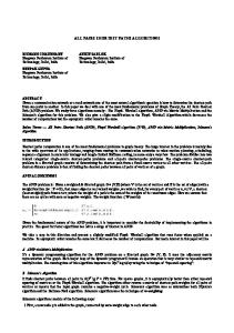
Link State in OSPFv3 (1)
NetA/PrefixA
NetA/PrefixA
Link local address mapping
IP6_global_1 IPv6_linklocal_1 R1
Link State Database: Link LSA (Adv Router: R1; #Prefixes: 1) Link local interface address: IPv6_linklocal_1; Address prefix: NetA
Inter-area prefix LSA (Adv Router: R1; #Prefixes: 1) Address prefix: NetA/PrefixA
89
Link State in OSPFv3 (2)
NetA/PrefixA
R1
R1
Link local address mapping
IP6_global_1 IP6_linklocal_1
Link local address mapping
IP6_global_2 IP6_linklocal_2 R2
NetA/PrefixA
R2
NetA/PrefixA
Link LSA (Adv Router: R1; #Prefixes:1)
Link LSA (Adv Router: R2; #Prefixes:1)
Link local address: IPv6_linklocal_1; Addr. prefix: NetA
Link local address: IPv6_linklocal_2; Addr. prefix: NetA
Router LSA (Adv Router: R1)
Router LSA (Adv Router: R2)
Neighbor RouterID: R2 - Point-to-point link to another router
Neighbor RouterID: R1 - Point-to-point link to another router
Inter-area prefix LSA (Adv Router: R1; #Prefixes: 1)
Inter-area prefix LSA (Adv Router: R2; #Prefixes: 1)
Address prefix: NetA/PrefixA
Address prefix: NetA/PrefixA
90
Link State in OSPF (3) R1 NetA/PrefixA
IP6_global_1 IP6_linklocal_1
Router ID R1
Router ID R2
Link local address mapping
Link local address mapping
NetA
(Transit network)
IP6_global_2 IP6_global_3 IP6_linklocal_2 IP6_linklocal_3
R2
R3
Link local address mapping
Router ID R3
Link LSA (Adv Router: R1; #Prefixes:1)
Router LSA (Adv Router: R1)
Link local address: IPv6_linklocal_1; Addr. prefix: NetA
Neighbor RouterID: R3 - Point-to-point link to transit network
Link LSA (Adv Router: R2; #Prefixes:1)
Router LSA (Adv Router: R2)
Link local address: IPv6_linklocal_2; Addr. prefix: NetA
Neighbor RouterID: R3 - Point-to-point link to transit router
Link LSA (Adv Router: R3; #Prefixes:1)
Router LSA (Adv Router: R3)
Link local address: IPv6_linklocal_3; Addr. prefix: NetA
Neighbor RouterID: R3 - Point-to-point link to transit router
Network LSA (Adv Router: R3; #Prefixes: 1)
Inter-area prefix LSA (Adv Router: R3; #Prefixes: 1)
Attached Routers: R1, R2, R3
Address prefix: NetA/PrefixA
91
Basic configuration differences (in Cisco)
In OSPFv3, a routing process does not need to be explicitly created
In OSPFv3, each interface must be enabled using commands in interface configuration mode
92
Enabling OSPF for IPv6 on an interface will cause a routing process, and its associated configuration, to be created
This feature is different from OSPFv2, in which interfaces are indirectly enabled using the router configuration mode
Steps to Configure OSPF for IPv6
Complete the OSPF network strategy and planning for your IPv6 network. For example, you must decide whether multiple areas are required
Enable IPv6 unicast routing
ipv6 unicast-routing
Enable OSPFv3 on the interface
ipv6 ospf area
(Optional) Configure OPSFv3 interface specific settings, including area, router priority, and OSPFv3 path cost
(Optional) Configure routing configuration mode, including summarization, and so on
93
specifics from router priority,
router route
Configuring OSPFv3 in Cisco IOS
Similar to OSPFv2
Interfaces configured directly
Replaces network command
“Native” IPv6 router mode
94
Prefixing existing Interface and Exec mode commands with “ipv6”
Not a sub-mode of router ospf
Configuration Modes in OSPFv3
Entering router mode
Entering interface mode
95
[no] ipv6 router ospf
[no] ipv6 ospf area
Exec mode
[no] show ipv6 ospf []
clear ipv6 ospf []
Cisco IOS OSPFv3 Specific Attributes
Configuring area range
96
[no] area range /
Showing new LSA
show ipv6 ospf [] database link
show ipv6 ospf [] database prefix
OSPFv3 Debug Commands
97
Adjacency is not appearing
[no] debug ipv6 ospf adj
[no] debug ipv6 ospf hello
SPF is running constantly
[no] debug ipv6 ospf spf
[no] debug ipv6 ospf flooding
[no] debug ipv6 ospf events
[no] debug ipv6 ospf lsa-generation
[no] debug ipv6 ospf database-timer
General purpose
[no] debug ipv6 ospf packets
[no] debug ipv6 ospf retransmission
[no] debug ipv6 ospf tree
Enabling OSPFv3 on an interface
Most of the OSPFv3 configuration is done on the interface
Router# configure terminal Router(config)# interface ethernet 0/0 Router(config-if)# ipv6 address 2001:400:1::1/64 Router(config-if)# ipv6 ospf 1 area 0 Router(config-if)# ipv6 ospf 1 cost 20
98
Configuring OSPFv3 routing specifics (1)
OSPFv3 requires general routing specifics commands to be configured from router configuration mode
Not in interface mode
Entering in OSPFv3 global configuration mode with
99
ipv6 router ospf PID
Configuring OSPFv3 routing specifics (2)
Basically, only one information required here: the RouterID
Unfortunately, OSPFv6 uses still a 32bit RouterID
The “ipv6 router-id ” command compulsory when an IPv6-only router is deployed
becomes
The OSPFv3 router ID can be expressed in dotted decimal, allowing easy overlay of an OSPFv3 network on an existing OSPFv2 network
If IPv4 is configured on the router, by default, the router ID is chosen in the same way as it is with OSPFv2
100
And, even more unfortunately, is not able to set that number automatically, when no IPv4 addresses are available
The highest IPv4 address configured on a loopback interface becomes the router ID If no loopback interfaces are configured, the highest address on any other interface becomes the router ID
Configuring OSPFv3 routing specifics (3)
Example
Router# configure terminal Router(config)# ipv6 unicast-routing
Router(config)# ipv6 router ospf 1 [*] Router(config-rtr)# router-id 2.2.2.2 [*] Upon issuing that command, the router prints the following text on the console: Router(config-rtr)# *Mar
1 00:00:52.575: %OSPFv3-4-NORTRID: OSPFv3 process 1 could
not pick a router-id, please configure manually Router(config-rtr)#
101
OSPFv3 Route Summarization Before Summarization:
After Summarization:
102
Conclusions
Very powerful (and very complex) protocol
Widely used in modern networks
103