2014 IEEE 25th International Symposium on Personal, Indoor and Mobile Radio Communications
On the Joint Design of Beamforming and User Scheduling in Multi-Cell MIMO Uplink Networks Bang Chul Jung1, Su Min Kim2 , Hyun Jong Yang3, and Won-Yong Shin4 Dept. of ICE, Gyeongsang National Univ., Tongyeong, Korea, E-mail:
[email protected] ACCESS Linneaus Centre, School of EE, KTH, Stockholm, Sweden, E-mail:
[email protected] 3 School of ECE, UNIST, Ulsan, Korea, E-mail:
[email protected] 4 Dept. of CSE, Dankook Univ., Yongin, Korea, E-mail:
[email protected] 1
2
Abstract—Due to the difficulty of coordination in cellular uplink networks, it is a practical challenge to achieve better throuhgput with a distributed scheduling. Futhermore, multiple antennas at mobile stations (MSs) can be utilized for reducing interference or for improving the desired signal strength. In this paper, we investigate a joint design of beamforming and user scheduling for multi-cell multiple input multiple output (MIMO) uplink networks. In the proposed scheme, each BS with M antennas adopts M random beamforming techniques and each MS with L antennas utilizes a single beamforming vector which minimizes the sum power of generating interferences to home cell as well as other cells. In each cell, then, the BS selects M MSs such that both sufficiently large desired signal power and sufficiently small generating interference are guaranteed. Numerical results show that the proposed scheme outperforms the existing distributed schemes in terms of sum-rate in practical environments. Index Terms—MIMO interfering multiple access channel, multiuser diversity, beamforming, user scheduling
I. I NTRODUCTION Interference management is one of the most challenging issues to provide better services in cellular networks. In general, each mobile station (MS) (or each base station (BS)) suffers from intra-cell interference as well as inter-cell interference in the cellular downlink (or in the cellular uplink). Interference alignment (IA) was recently proposed by Cadambe and Jafar for fundamentally solving the interference problem [1]. It was shown that the IA achieves the optimal degrees-of-freedom in the K-user interference channel with time-varying channel coefficients. Subsequent work has shown that the IA can be applicable to other wireless networks including multiple-input multiple-output (MIMO) interference channels [2], [3] and cellular networks [4]–[9]. On the other hand, there have been remarkable techniques that exploit usefulness of fading in a single cell network, thus resulting in a multiuser diversity (MUD) gain: opportunistic scheduling [10], opportunistic beamforming [11], and random beamforming [12]. Moreover, scenarios obtaining the MUD gain have been studied in ad hoc networks [13], in cognitive radio networks [14], and multi-cell downlink and uplink networks [15], [16]. In particular, the authors of [16] proved that the optimal MUD gain can be achieved with a distributed user scheduling even in the presence of inter-cell interference when both MS and BS have a signle antenna. When both MS and
978-1-4799-4912-0/14/$31.00 ©2014 IEEE
BS have multiple antennas, however, it remains open how to design a joint user scheduling and beamforming at both MS and BS, which efficiently exploits the MUD gain in multi-cell uplink networks. In this paper, we propose a joint beamforming and user scheduling technique which efficiently exploits the MUD gain in time-division duplexing (TDD) K-cell MIMO uplink networks, where there exist N MSs with L antennas and one BS with M antennas in each cell. As for the beamforming, each BS employs M random receive beamforming vectors and each MS adopts a single beamforming vector which minimizes the sum of generating interference to home cell and other cells. In each cell, the BS selects M MSs such that both sufficiently large desired signal power and sufficiently small generating interference are guaranteed. Note that the proposed scheme operates with a distributed manner and requires only local channel state information (CSI) at each MS as in [2]. Simulation results show that the proposed scheme outperforms the conventional distributed scheduling algorithms in practical environments. II. S YSTEM M ODEL We consider a TDD K-cell MIMO IMAC model where each cell consists of a single BS with M antennas and N MSs, each of which has L antennas. An example for K = 3, N = 6, L = 2, and M = 3 is illustrated in Fig. 1. We assume a block fading model where the channel matrices are constant during a transmission block (e.g., frame) and independently change for every transmission block. Then, the received signal vector at the i-th BS, yi , is given by M " ! [i,j] [i,j] yi = βi Hi w[i,j] x[i,j] j=1
+
M " K ! ! [k,j] [k,j] βi Hi w[k,j] x[k,j] + zi ,
(1)
k=1,k̸=i j=1 [i,j]
where βk
denotes the large-scale path-loss from the j-th user [i,j]
[i,j] −α
in the i-th cell to the k-th BS, 0 < βk ! dk ≤ 1 where [i,j] dk ≥ 1 represents the distance from the j-th MS in the ith cell to the k-th BS and α denotes the path-loss exponent. [i,j] Hk ∈ CM×L denotes the small-scale fading channel matrix
502
where ui,m ∈ CM×1 denotes the orthonormal vector for the m-th received signal. Here, ui,m ’s are generated in accordance with an isotropic distribution. These randomly generated beamforming matrices are broadcasted by BSs to all users in the network before scheduling2. After receive beamforming, the received signal vector at the i-th BS is expressed as: M " ! [i,π ] [i,π ] ri = βi i,m Ui H Hi i,m w[i,πi,m ] x[i,πi,m ]
MS5 MS4 MS6
MS3
BS1
MS1
MS2
MS1
MS6 MS2
BS3 MS1
MS2
MS3
MS5
+
BS2
+ ˜zi ,
: Scheduled users MS4
MS5
: Non-scheduled users : Inter-cell interference
Fig. 1.
M " ! [k,π ] [k,π ] βi k,m Ui H Hi k,m w[k,πk,m ] x[k,πk,m ]
k=1,k̸=i m=1
MS4
MS3
MS6
m=1 K !
MIMO IMAC model where K = 3, N = 6, L = 2, and M = 3.
(2)
where πi,m denotes the index of the scheduled MS for the m-th receive beamforming vector in the i-th cell and ˜ zi = Ui H zi ∼ CN (0, N0 IM ). Then, the received signal for m∗ -th receive beamforming vector of i-th BS is expressed as: " [i,π ∗] [i,π ∗] ri,m∗ = βi i,m ui,m∗ H Hi i,m w[i,πi,m∗ ] x[i,πi,m∗ ] & '( ) desired signal
from the j-th user in the i-th cell to the k-th BS and each element of the channel matrix is assumed to follow a complex Gaussian distribution with zero mean and unit variance, and to be independent across different i, j, and k. w[i,j] ∈ CL×1 denotes the transmit beamforming vector of the j-th MS in the i-th cell and x[i,j] represents the transmitted data symbol of the j-th MS in the i-th cell. In this paper, we assume that each BS selects M MSs at a time slot and the selected M MSs send their messages simultaneously through a single spatial stream by using L antennas. zi ∈ CM×1 denotes the circular symmetric complex additive white Gaussian noise vector with zero mean and covariance matrix N0 IM , zi ∼ CN (0, N0 IM ) where N0 represents the noise spectral density. We also assume that% each MS has an average transmit power constraint #$ $2 E $x[i,j] $ ≤ P , ∀i, j and then SNR = P/N0 . III. R ECEIVE B EAMFORMING & U SER S CHEDULING
In this section, we first propose a distributed and opportunistic scheduling (DOS) which exploits two threshold values for desired signal power and generating interference power, respectively. In this section, we assume that the transmit beamforming vectors are already determined at each MS, and we will show how to design the transmit beamforming vectors in the next section. Each BS generates M random receive beamforming vectors orthogonal to each other for each time slot and matches each beamforming vector to a single MS in the corresponding cell1 . The beamforming matrix for the i-th BS, Ui ∈ CM×M , is defined as
M !
+
m=1,m̸=m∗
+
&
" [i,π ] [i,π ] βi i,m ui,m∗ H Hi i,m w[i,πi,m ] x[i,πi,m ] '(
K !
M " ! [k,π ] [k,π ] βi k,m ui,m∗ H Hi k,m w[k,πk,m ] x[k,πk,m ]
k=1,k̸=i m=1
&
)
intra-cell interference
'(
inter-cell interference
+ z˜i ,
(3)
where z˜i = ui,m∗ H zi ∼ CN (0, N0 ). Assuming the channel reciprocity of TDD system, it is [i,j] possible to obtain all the received channel matrices Hk for the j-th user in the i-th cell by using a pilot signaling from BSs in downlink, where j ∈ {1, . . . , N } and i, k ∈ {1, . . . , K} [7]. In the proposed DOS protocol, at each scheduling instance, the j-th user in the i-th cell finds m∗ ∈ {1, . . . , M } satisfying the following criteria by using both receive " beamforming [i,j]
[i,j]
matrices, {U1 , . . . , UK }, and channel matrices, βk Hk , which are obtained by BSs’ broadcast and pilot signaling, respectively. $ $2 $ [i,j] $ [i,j] (4) (C1) βi $ui,m∗ H Hi w[i,j] $ ≥ ηtr , (C2)
M !
[i,j]
βi
m=1,m̸=m∗
+
K !
M !
k=1,k̸=i m=1
[i,j]
βk
$ $2 $ $ [i,j] $ui,m H Hi w[i,j] $
$ $2 $ $ [i,j] $uk,m H Hk w[i,j] $ ≤ ηI , (5)
Ui ! [ui,1 , ui,2 , . . . , ui,M ],
where ηtr and ηI denote the pre-determined positive threshold values. The transmit beamforming vector w[i,j] of the i-th
1 It can be regarded as an uplink version of the conventional random beamforming technique which was originally proposed for downilnk [12].
2 By using pseudo-random pattern, U can be informed to users without i any signaling process as in [7].
503
)
M selected users
[Cell 1]
u1,3
MS1
! [1,3] [1,3] β1 H1 w[1,3]
! [2,1] [2,1] β1 H1 w[2,1]
! [2,3] [2,3] β1 H1 w[2,3]
MS2 u1,2
! [1,1] [1,1] β1 H1 w[1,1]
! [2,2] [2,2] β1 H1 w[2,2]
u1,1
! [1,2] [1,2] β1 H1 w[1,2]
BS1
MS3 [Cell 2]
u2,3
MS1
! [1,3] [1,3] β2 H2 w[1,3]
MS2 u2,2
MS3
! [2,3] [2,3] β2 H2 w[2,3] ! [1,2] [1,2] β2 H2 w[1,2] ! [2,1] [2,1] β2 H2 w[2,1]
! [1,1] [1,1] β2 H2 w[1,1]
u2,1
! [2,2] [2,2] β2 H2 w[2,2]
BS2
M selected users
Fig. 2. Geometric interpretation of the received signals at BSs in the proposed DOS where K = 2, L = 2, and M = 3 (π1,1 = π2,1 = 1, π1,2 = π2,2 = 2, π1,3 = π2,3 = 3).
user in the j-th cell is assumed to be optimally determined according to transmission strategy, which are explained in next section. Criterion (C1) is satisfied if the desired signal power strength is greater than or equal to ηtr , which is determined in such a way that the users’ desired signal power received at the corresponding BS is sufficiently large to obtain MUD gain. On the other hand, criterion (C2) is satisfied if the sum power of (M K −1) interference signals generated by the MS to its own BS (i.e., intra-cell interference) and other BSs (i.e., inter-cell interference) is less than or equal to ηI , which is determined to a sufficiently small value to assure that the cross-channels of the selected MS are in deep-fade, while not preventing the system from obtaining MUD gain. The left-hand side of (5) denotes the sum power of intra- and inter-cell interferences generated by the j-th user to other BSs. In this paper, we call this leakage of interference (LIF). Therefore, the LIF of the j-th user in the i-th cell for the m∗ -th receive beamforming vector is defined as: L(i, j, m∗ ) ! +
M !
m=1,m̸=m∗ K !
$ $2 $ [i,j] $ [i,j] βi $ui,m H Hi w[i,j] $
M !
k=1,k̸=i m=1
[i,j]
βk
$ $2 $ $ [i,j] $uk,m H Hk w[i,j] $ .
(6)
their corresponding scheduling metrics in (4) and (5) to the corresponding BS. Otherwise, it feeds back nothing. This feedback strategy implies that the MSs whose the criteria are satisfied request a packet transmission to their corresponding BS. Thereafter, each BS randomly selects one MS among the MSs that feed back the same beamforming vector index m∗ ∈ {1, . . . , M }. If there exists a beamforming vector index that was not fed back from any users, the beamforming vector is not used for signal decoding. This may cause some performance degradation, but we can reduce the probability of the event if the two threshold values are set appropriately and the number of users in a cell increases. Finally, the selected MSs in each cell transmit their packets. Then, each BS decodes the MSs’ signals by using the corresponding receive beamforming vectors, while treating all the interference as noise. Fig. 2 shows a geometric interpretation of the proposed scheme. IV. T RANASMIT B EAMFORMING & ACHIEVABLE S UM -R ATE In this section, we first analyze the achievable sum-rate of the proposed scheme and propose the transmit beamforming technqiue at MSs. The achievable sum-rate of the proposed scheme is expressed as:
When an MS has at least one index m∗ satisfying the both criteria (C1) and (C2), it feeds back the indices and
504
R(SNR) =
M K ! !
k=1 m∗ =1
Rk,m∗ (SNR),
(7)
where Rk,m∗ (SNR) denotes the achievable rate of the πk,m∗ th MS (i.e., for the selected MS using the m∗ -th receive beamforming vector in the k-th cell). Assuming the sum of intraand inter-cell interference to follow Gaussian distribution, the achievable rate of the πi,m∗ -th MS is lower-bounded as: ≥ Pi,m∗ · log (1 + SINRi,m∗ ) ,
where
M !
[i,πi,m ]
βi
m=1,m̸=m∗
+
K !
M !
[k,π ] βi k,m
k=1,k̸=i m=1
$ $2 $ $ [i,π ] $ui,m∗ H Hi i,m w[i,πi,m ] $
$ $2 $ $ [k,π ] $ui,m∗ H Hi k,m w[k,πk,m ] $ , (10)
which implies the sum power of intra- and inter-cell interference for the scheduled MS πi,m∗ using the m∗ -th receive beamforming vector in the i-th cell. In the proposed scheme, each MS finds the transmit beamforming vector that minimizes its LIF by using well-known singular value decomposition (SVD). The LIF of the j-th user in the i-th cell for a given receive beamforming vector m∗ ∈ {1, . . . , M } is expressed as: M !
LSVD (i, j, m∗ ) =
[i,j]
βi
m=1,m̸=m∗ K !
+
M !
$ $2 $ $ [i,j] $ui,m H Hi w[i,j] $
[i,j]
βk
k=1,k̸=i m=1 M !
≤
m=1,m̸=m∗ K !
+
$ $2 $ $ [i,j] $uk,m H Hk w[i,j] $
$ $2 $ $ [i,j] $ui,m H Hi w[i,j] $
M $ $2 ! $ $ [i,j] $uk,m H Hk w[i,j] $
* *2 ∗ * * = *G[i,j,m ] w[i,j] * ! L˜SVD (i, j, m∗ ), (11)
where G[i,j,m ] ∈ C(KM−1)×L is defined as (12) at the top ∗ ˜ [m ] ∈ CM×(M−1) is defined by of the next page, where U i ∗
˜ [m ] ! [ui,1 , . . . , ui,m∗ −1 , ui,m∗ +1 , . . . , ui,M ] . U i [i,j,m∗ ]
Let the SVD of G ∗
[i,j,m∗ ]
(13)
be denoted by ∗
∗
G[i,j,m ] = Ω[i,j,m ] Σ[i,j,m ] V[i,j,m
∗
[i,j,m∗ ]
]H
,
∈ C , V ∈ C where Ω ∗ consists of L orthonormal columns, and Σ[i,j,m ] (KM−1)×L
8
Optimal Point 6
4
Max−SNR Min−LIF Proposed
2
0
0
0.5
1
(14) L×L
=
1.5
2
2.5
3
3.5
4
I
Fig. 3. Sum-rate versus ηI for K = 2, N = 20, M = L = 3, and SNR = 20 dB.
, + [i,j,m∗ ] [i,j,m∗ ] [i,j,m∗ ] in which σ1 diag σ1 , . . . , σL ≥ ··· ≥ [i,j,m∗ ]
[i,j]∗
σL . Then, the optimal weight vector wSVD of the j-th user using the m∗ -th receive beamforming vector in the i-th cell is determined as *2 * ∗ * * [i,j]∗ [i,j,m∗ ] wSVD = arg min *G[i,j,m ] v* = vL , (15) v
where
[i,j,m∗ ] vL
∗
denotes the L-th column of V[i,j,m ] . V. N UMERICAL R ESULTS
For performance comparison, two baseline schemes are considered: max-SNR and min-LIF schemes. In the max-SNR scheme, the vector w[i,j] is designed as , + transmit beamforming [i,j]
k=1,k̸=i m=1
∗
10
(8)
where Pi,m∗ denotes the probability that at least one MS satisfying both the criteria (C1) and (C2) exists for the m∗ -th receive beamforming vector of the i-th BS. In accordance with Eq. (3), the signal-to-interference-plusnoise-ratio (SINR) of the πi,m∗ -th MS is written as: $ $2 ∗] $ ∗] [i,π [i,π $ βi i,m $ui,m∗ H Hi i,m w[i,πi,m∗ ] $ SINRi,m∗ = , (9) 1/SNR + I(i, πi,m∗ , m∗ ) I(i, πi,m∗ , m∗ ) !
12
Sum Rates (bits/s/Hz)
Ri,m∗ (SNR) ≥ log (1 + SINRi,m∗ )
14
H
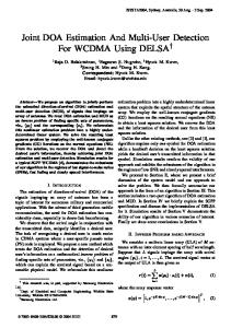
to maximize desired channel gain. w[i,j] = uH i,m∗ Hi In addition, the users with higher gains of the desired channels are selected. In the min-LIF scheme [8], the design of w[i,j] as well as the user scheduling is performed only to minimize the LIF in (6). Fig. 3 shows sum-rates versus ηI for K = 2, N = 20, M = L = 3, and SNR = 20 dB. Note that the condition (4) was replaced in the M users $ simulations by $choosing $2 [i,j] $ [i,j] with the highest βi $ui,m∗ H Hi w[i,j] $ among the users satisfying the condition (5), which only improves the sumrate of the proposed scheme. It is shown from the figure that optimal ηI can be found by the numerical evaluation of sumrates for given N and SNR, with which the proposed scheme outperforms the baseline schemes. Fig. 4 depicts sum-rates versus SNR for K = 2, N = 20, and M = L = 3. For the proposed scheme, ηI was optimized for each N and SNR. The sum-rate of the max-SNR shows only marginal improvement with respect to SNR due to constant interference level. The proposed scheme effectively suppresses the interference level and improves the desired channel gains simultaneously. The proposed scheme yields higher sum-rates in all SNR regime than the baseline schemes,
505
G[i,j,m
∗
]
⎤T ⎡ ,T + ,T ,T ⎥ + + ⎢+ [m∗ ]H [i,j] ,T + H [i,j] ,T [i,j] [i,j] [i,j] ⎥ , ˜ !⎢ Hi , U1 H1 , . . . , Ui−1 H Hi−1 , Ui+1 H Hi+1 , . . . , UK H HK ⎦ ⎣ Ui & '( ) & '( ) intra-cell interference
inter-cell interference
scheme outperforms the existing distributed schemes in terms of sum-rate. However, the thresholds should be carefully chosen for better throughput and we leave the issue on the optimal thresholds for future work.
15 14 13
Sum Rates (bits/s/Hz)
12 11
ACKNOWLEDGEMENT
10
This research was supported by Basic Science Research Program through the National Research Foundation of Korea (NRF) funded by the Ministry of Education (2013R1A1A2A10004905).
9 8 7
Max−SNR Min−LIF Proposed
6 5 4
0
5
10
15
20
R EFERENCES
25
30
SNR (dB)
Fig. 4.
Sum-rate versus SNR for K = 2, N = 20, and M = L = 3.
26
Max−SNR Min−LIF Proposed
24 22
Sum Rates (bits/s/Hz)
(12)
20 18 16 14 12 10 8 6 1
10
2
10
3
10
N
Fig. 5.
Sum-rate versus N for K = 2, M = L = 3, and SNR=20dB.
whereas the min-LIF scheme is inferior to the max-SNR scheme in the low SNR regime. Fig. 5 shows sum-rates versus N for K = 2, M = L = 3, and SNR = 20 dB. It is seen that the proposed scheme exhibits the highest sum-rate with respect to N . VI. C ONCLUSION In this paper, we proposed a joint design of beamforming and user scheduling for multi-cell multiple input multiple output (MIMO) uplink networks, which efficiently exploits multiuser diversity gain even though both the user scheduling at the BS and beamforming at each MS are performed with a distributed manner in each cell. Numerical results show that in a practical setting of the multi-cell network, the proposed
[1] V. R. Cadambe and S. A. Jafar, “Interference alignment and degrees of freedom of the K-user interference channel,” IEEE Trans. Inf. Theory, vol. 54, no. 8, pp. 3425–3441, Aug. 2008. [2] K. Gomadam, V. R. Cadambe, and S. A. Jafar, “A distributed numerical approach to interference alignment and applications to wireless interference networks,” IEEE Trans. Inf. Theory, vol. 57, no. 6, pp. 3309–3322, Jun. 2011. [3] T. Gou and S. A. Jafar, “Degrees of freedom of the K-user M × N MIMO interference channel,” IEEE Trans. Inf. Theory, vol. 56, no. 12, pp. 6040–6057, Dec. 2010. [4] C. Suh, M. Ho, and D. Tse, “Downlink interference alignment,” IEEE Trans. Commun., vol. 59, no. 9, pp. 2616–2626, Sep. 2011. [5] C. Suh and D. Tse, “Interference alignment for celluar networks,” in Proc. 46th Annual Allerton Conf. on Commun., Control, and Computing, Monticello, IL, Sep. 2008. [6] B. C. Jung and W.-Y. Shin, “Opportunistic interference alignment for interference-limited cellular TDD uplink,” IEEE Commun. Lett., vol. 15, no. 2, pp. 148–150, Feb. 2011. [7] B. C. Jung, D. Park, and W.-Y. Shin, “Opportunistic interference mitigation achieves optimal degrees-of-freedom in wireless multi-cell uplink networks,” IEEE Trans. Commun., vol. 60, no. 7, pp. 1935–1944, Jul. 2012. [8] H. J. Yang, W. -Y. Shin, B. C. Jung, and A. Paulraj, “Opportunistic interference alignment for MIMO interfering multiple-access channels,” IEEE Trans. Wireless Commun., vol. 12, no. 5, pp. 2180–2192, May 2013. [9] H. J. Yang, W. -Y. Shin, B. C. Jung, C. Suh, and A. Paulraj, “Opportunistic downlink interference alignment,” Preprint, [Online] Available: http://arxiv.org/abs/1312.7198. [10] R. Knopp and P. Humblet, “Information capacity and power control in single cell multiuser communications,” in Proc. IEEE Int. Conf. Commun. (ICC), Seattle, WA, Jun. 1995, pp. 331–335. [11] P. Viswanath, D. N. C. Tse, and R. Laroia, “Opportunistic beamforming using dumb antennas,” IEEE Trans. Inf. Theory, vol. 48, no. 6, pp. 1277–1294, Aug. 2002. [12] M. Sharif and B. Hassibi, “On the capacity of MIMO broadcast channels with partial side information,” IEEE Trans. Inf. Theory, vol. 51, no. 2, pp. 506–522, Feb. 2005. [13] W.-Y. Shin, S.-Y. Chung, and Y. H. Lee, “Parallel opportunistic routing in wireless networks,” IEEE Trans. Inf. Theory, to appear. [14] T. W. Ban, W. Choi, B. C. Jung, and D. K. Sung, “Multi-user diversity in a spectrum sharing system,” IEEE Trans. Wireless Commun., vol. 8, no. 1, pp. 102-106, Jan. 2009. [15] W.-Y. Shin and and B. C. Jung, “Network coordinated opportunistic beamforming in downlink cellular networks,” IEICE Trans. Commun., vol. E95-B, no. 4, pp. 1393–1396, Apr. 2012. [16] W. -Y. Sin, D. Park, and B. C. Jung, “Can one achieve multiuser diversity in uplink multi-cell networks?,” IEEE Trans. Commun., vol. 60, no. 12, pp. 3535-3540, Dec. 2012.
506