USO0RE43891E
(19) United States (12) Reissued Patent
(10) Patent Number: US (45) Date of Reissued Patent:
Golden (54)
5,682,133 5,766,956 5,938,706 5,963,657 5,986,543 6,078,265 6,271,745
MULTI SENSOR DETECTION, STALL TO STOP AND LOCK DISABLING SYSTEM
(76) Inventor: Larry Golden, Mauldin, SC (US)
(21) Appl.No.: 13/065,837 (22) Filed:
Mar. 31, 2011 Related US. Patent Documents
A A A A A A B1
10/1997 6/1998 8/1999 l0/l999 11/1999 6/2000 8/2001
RE43,891 E Jan. 1, 2013
Johnson Groger et al. Feldman Bowker et al. Johnson Bonder et a1. Anzai et a1.
6,374,652 B1
4/2002 Hwang
6,542,076 B1 6,542,077 B2 6,588,635 B2
4/2003 Joao 4/2003 Joao 7/2003 Vor Keller et a1.
(Continued)
Reissue of:
(64) Patent No.: Issued:
7,636,033
OTHER PUBLICATIONS
Dec. 22, 2009
Appl. No.:
12/155,573
Filed:
Jun. 6, 2008
U.S. Appl. No. l2/802,00l, ?led May 27, 2010, Golden.
US. Applications: (63) Continuation-in-part of application No. 11/397,118,
(Continued) Primary Examiner * Van T. Trieu
?led on Apr. 5, 2006, noW Pat. No. 7,385,497.
(57) (51)
(52) (58)
Int. Cl. B60R 25/10 G08B 1/08
(2006.01) (2006.01)
sample for chemical, biological and radiological compounds,
US. Cl. ........ .. 340/426.11; 340/426.16; 340/539.11 Field of Classi?cation Search ............. .. 340/425.5,
340/426.11*426.19, 426.25, 521, 522, 539.1, 340/539.11, 539.13, 539.22, 539.26, 540, 340/5453, 600; 701/29, 32, 36, 2, 29.1, 701/31.5, 32.2, 32.4, 32.9; 702/22; 307/102, 307/10.3
See application ?le for complete search history. (56)
References Cited U.S. PATENT DOCUMENTS 4,385,469 A 5/1983 Scheuerp?ug 4,544,267 4,586,441 4,792,226 5,222,152 5,223,844 5,233,404 5,557,254
A A A A A A A
10/1985 5/1986 12/1988 6/1993 6/1993 8/1993 9/1996
Schiller Zekich Fishbine et al. Fishbine et al. Mansellet al. Lougheed et al. Johnson
ABSTRACT
A multi sensor detection and disabling lock system includes detector cases for holding interchangeable detectors that agents and elements, With each detector case disposed in or
upon the monitored product Whereupon light alarm indicators (color coded) on the detector case light up When a speci?c compound or agent is detected Whereupon the detector case transmits detection information to a monitoring computer terminal and transmits a signal to a lock disabler engaged to the product to lock or disable the product’s lock thereby
preventing untrained, unauthorized and unequipped individu al’s from gaining access and entry to the product, and also preventing further contamination of the area. An authorized individual resets the detection system, and the system’s poWer source is electrical, battery or computer generated. In addition, the detection system can be interconnected to sur veillance toWers scanning detector cases disposed at seaport
docks, freight depots and rail terminals for monitoring con tainers being prepared for shipment or sitting on docks for
long periods of time. 75 Claims, 13 Drawing Sheets
US RE43,891 E Page 2 US. PATENT DOCUMENTS 6,610,977 B2 8/2003 Megerle 6,613,571 B2 6,628,813 B2 6,647,328 B2 6,738,697 B2*
6,923,509 6,980,092 7,005,982 7,034,683 7,103,460 7,109,859 7,116,798 7,346,439 7,385,497 7,397,363 7,636,033 2003/0206102 2004/0107028 2005/0195069 2006/0250235 2008/0122595 2008/0234907 2010/0159983 2011/0178655
B1 B2 B1 B2 B1 B2 B1 B2 B2 B2 B2 A1 A1 A1 A1 A1 A1 A1 A1
9/2003 Cordery et al. 9/2003 Scott et al. 11/2003 Walker 5/2004
8/2005 12/2005 2/2006 4/2006 9/2006 9/2006 10/2006 3/2008 6/2008 7/2008 12/2009 11/2003 6/ 2004 9/ 2005 1 1/ 2006 5/ 2008 9/ 2008 6/2010 7/201 1
Breed ........................ .. 701/31.5
Barnett Turnbull et al. Frank GhaZarian Breed Peeters ChaWla Bodin Golden Joao Golden Joao Catalano Dunand Astrin Yamamichi Labuhn Golden Golden
OTHER PUBLICATIONS A newspaper article of Mr. Melvin Sullivan and his family that references the date, Mar. 6, 2001. A letter of response Mr. Sullivan received from Pfeiffer & Gantt, PA,
dated Sep. 16, 2002. A “Certi?cate of Existence” Bright Idea Inventor, LLC. Nov. 6, 2002. Operating Agreement of Bright Idea Inventor, LLC received from Pfeiffer & Gantt, PA, dated Nov. 13, 2002. A “Membership Certi?cate” received from Bright Idea Inventor, LLC dated Nov. 13, 2002. A letter of response Golden received from the Honorable Congress man from Maryland, Elijah E. Cummings, dated Dec. 16, 2002. A newspaper article of Mr. Melvin Sullivan and Mr. Larry Golden, dated, Feb. 27-Mar. 5, 2003. A letter of response Golden received from the Honorable Senator
On Jul. 10, 2005, an “Inventor’s Of?cial Record of Invention”, Was ?led in my name (Golden) at “The Law Of?ce of David P Gaudio,
PC; The Inventors Network”
On Aug. 23, 2005, “Disclosure Document Registration”. On Apr. 5, 2006, “Patent Application” Was ?led in my name (Golden) at the United States Patent & Trademark Of?ce in Washington, DC.
On Jun. 06, 2008, “Continuance-In-Part, (CIP) Application” Was ?led in my name (Golden) at the United States Patent & Trademark
Of?ce in Washington, DC. On Jun. 10, 2008, Golden Was issued a Patent (7,385,497) the “Multi
sensor detection and lock disabling system” On Dec. 22, 2009, Golden Was issued a Patent (7,636,033) the “Multi
sensor detection, stall-to-stop, and lock disabling system” On Jan. 20, 2010, a “Continuation Application” (U.S. Appl. No. 12/657,356) Was ?led in my name (Golden) at the United States
Patent & Trademark Of?ce in Washington, DC.
On May 27, 2010, a “Continuation Application” (U.S. Appl. No. 12/802,001) Was ?led in my name (Golden) at the United States
Patent & Trademark Of?ce in Washington, DC. Reissue ofU.S. Patent No. 7,636,033; “Swear Back”; In accordance to Title 374Code of Federal Regulations Patents, Trademarks, and
Copyrights; Apr. 8, 2011. Reissue of US. Patent No. 7,636,033; “SWGBIbQCkiHISIOI'Y of
Work”; Apr. 8, 2011. United States Patent and Trademark Of?ce; Of?ce Action from US.
Appl. No. 11/397,118; mailed Nov. 14, 2007; Alexandria, Virginia, USA; pp. 1-12; (12 pages). United States Patent and Trademark Of?ce; Of?ce Action from US.
Appl. No. 12/ 155,573; mailed Apr. 9, 2009; Alexandria, Virginia, USA; pp. 1-7; (7 pages). United States Patent and Trademark Of?ce; Of?ce Action from US.
Appl. No. 12/155,573; mailed Jul. 30, 2009; Alexandria, Virginia, USA; pp. 1-9; (9 pages). United States Patent and Trademark Of?ce; Notice of Allowability from US. Appl. No. 12/155,573; mailed Oct. 28, 2009; Alexandria,
Virginia, USA; pp. 1-5; (5 pages). United States Patent and Trademark Of?ce; Of?ce Action from US.
Appl. No. 12/657,356; mailed Jul. 12, 2010; Alexandria, Virginia, USA; pp. 1-14; (14 pages). United States Patent and Trademark Of?ce; Notice of Allowability from US. Appl. No. 12/657,356; mailed Mar. 10, 2011; Alexandria,
from South Carolina, Ernest F. Hollings, dated May 21, 2003.
Virginia, USA; pp. 1-4; (4 pages).
A letter of response Golden received from the Of?ce of the Vice
United States Patent and Trademark Of?ce; Of?ce Action from US.
President, Dick Cheney, dated Jun. 3, 2003. A letter of response Golden received from the Honorable Senator
Appl. No. 12/802,001; mailed May 27, 2010; Alexandria, Virginia, USA; pp. 1-16; (16 pages).
from South Carolina, Ernest F. Hollings, dated Oct. 1, 2003.
United States Patent and Trademark Of?ce; Of?ce Action from US.
A letter of response Golden received from the Honorable Senator
Appl. No. 12/802,001; mailed May 27, 2011; Alexandria, Virginia, USA; pp. 1-14; (14 pages).
from South Carolina, Lindsey 0. Graham, dated Oct. 21, 2003. A letter sent to the President of the United States George W. Bush, the President’s Cabinet, the United States Senate and the Congressional
Black Caucus, dated May 23, 2005.
United States Patent and Trademark Of?ce; Of?ce Action; Of?ce
Action from US. Appl. No. 12/ 802,001; copyright and mailing date Dec. 12, 201 1, pp. 1-9, publisher United States Patent and Trademark
On Nov. 17, 2004, “Disclosure Document Registration” Was ?led in my name (Golden) at the United States Patent & Trademark Of?ce in
Of?ce, Alexandria, Virginia, USA; (9 pages).
Washington, DC.
* cited by examiner
US. Patent
Jan. 1, 2013
INTERNET CONNECTION GPS
CONNECTION POWER SOURCE
/34
Sheet 1 0113
US RE43,891 E
US. Patent
Jan. 1, 2013
Sheet 2 0f 13
14
US RE43,891 E
60
58
I I“! I I‘ I“ Ir 56
%I|l I I I‘, I I I I / Fig. 3a
58
I" I
I‘ I‘ I' I Fig. 3b
US. Patent
Jan. 1, 2013
Sheet 3 0f 13
US RE43,891 E
,112
POWER SOURCE
F n. 5
US. Patent
Jan. 1, 2013
Sheet 4 0f 13
2o
POWER SOURCE
US RE43,891 E
US. Patent
Jan. 1, 2013
INTERNET CONNECTION GPS CONNECTION POWER SOURCE
/34
Sheet 6 0f 13
US RE43,891 E
US. Patent
26
Jan. 1, 2013
5 _____________________
Sheet 7 0f 13
g -------------------
\ s
US RE43,891 E
i --------------------
E5
I .....‘F .... _ A ....
32 3\4
2*“30
.....................
............. -.
36
3,8 Fig. 10
76
NO YES 8°\ souuo ALARM
1 82M
LIGHTALARM
74\)
I 40\
CPU I
84\
86“
READINGS
RESET 76
Fig. 1 1
| SENSINM ( STOP )
94
US. Patent
Jan. 1, 2013
Sheet 8 0f 13
US RE43,891 E
76
881)
NO YES
82\ LIGHTALARM
I 80\ SOUNDALARM
I 84\
Fig. 12
READINGS
I 9°\ DETECTOR RESET
78\ SENSING MODE
I STOP I 76
46\
DETECTOR
4o\
I
12\_ tICASE
921)
I
94
LOCK/DISABLE \
LOCK SIGNAL
\
DISARM AND
I -
H9‘ 13
96
RESET
98\ DETECTION MODE
US. Patent
Jan. 1, 2013
DETECTOR
Sheet 9 0f 13
US RE43,891 E
100
\I:
12\
x
CASE
\ WATCHTOWER
DISABLER / 62
DISABLE AND DISARM
|
RESET
ACCESS
\
\
106 DETECTION
MODE
LIGHTALARM M42
DENIED
INDICATOR 114
101
\ MONITORING TERMINAL
108
/
120\ LOCK/DISABLE SIGNAL
Fi - 14
9
T
122\
CLEANUP MEASURES
124 11s
Fig- 15
DETEcTIoN
MODE
RESET
US. Patent
Jan. 1, 2013
Sheet 10 0f 13
US RE43,891 E
138
Fig. 16
US. Patent
Jan. 1, 2013
Sheet 11 0113
US RE43,891 E
I: _
_
156
170
E \;—————J/ 1, " “ f?/
/
INTERNET CONNECTION 1 72
1 5O \
<
\
164
-
\
111ml ‘1111
GPS
CONNECTION POWER SOURCE
\@090
11/ K
K
L
/
/
\
184
Fig. 1 7
US. Patent
Jan. 1, 2013
Sheet 12 0113
US RE43,891 E
sav y/‘I ? >1
/21s
196
194
200
198
192
138/
Fig. 1a
188)
US. Patent
Jan. 1, 2013
194
200
198
192
Sheet 13 0f 13
US RE43,891 E
138/“ A
Fig. 19
188")
US RE43,891 E 1
2
MULTI SENSOR DETECTION, STALL TO STOP AND LOCK DISABLING SYSTEM
from shipping containers to school lockers. Thus, the prior art discloses a Wide range of security measures and systems.
For example, the Fishbine et a1. patent (US. Pat. No. 4,792, 226) discloses an optical ?ngerprinting system that includes
Matter enclosed in heavy brackets [ ] appears in the original patent but forms no part of this reissue speci?ca
an optics/processor unit, a video monitor, a data terminal, and
a printer for collecting and storing data characteristics of all ten individual ?ngerprints for printing demographic informa
tion; matter printed in italics indicates the additions made by reissue.
tion and ?ngerprint images as desired on a standard booking or applicant card.
RELATED APPLICATIONS
[This application] More than one reissue application has been?ledfor the reissue of US. Pat. No. 7,636,033 B2. The reissue applications are application Ser. No. 13/199, 853?led Sep. 9, 20]] which is a divisional reissue of US. Pat. No. 7,636,033 B2, and the present application Ser. No. 13/065, 837?led Mar 3], 20]] which is a reissue of US. Pat. No. 7,636, 033 B2. Thepresent application is a reissue ofU.S. Pat. No. 7,636,033 B2 and claimspriority to thispatent the entire contents of which are incorporated by reference in their entirety hereinfor allpurposes. US. Pat. No. 7, 636,033 B2 is a continuation-in-part of US. patent application Ser. No. 11/397,118 titled “Muti Sensor Detection and Lock Dis abling System” ?led on Apr. 5, 2006 and is noW US. Pat. No.
7,385,497, the complete subject matter of Which is incorpo
The Schiller patent (US. Pat. No. 4,544,267) discloses a ?nger identi?cation unit that includes a ?ngerprint scanning apparatus using a collimated beam of light to interrogate the ?ngerprint of a ?nger placed against a platen so that succes
sive scan positions produce signals containing ?ngerprint information.
The Fishbine et a1. patent (US. Pat. No. 5,222,152) dis
closes a portable ?ngerprint scanning apparatus for optically
scanning and recording ?ngerprint images and Wirelessly 20
transmitting such images to a mobile processing unit for
veri?cation and background checking. The Lougheed et a1. patent (US. Pat. No. 5,233,404) dis closes an optical scanning apparatus that uses a linear charge
coupled device (CCD) for recording the image of a ?ngerprint 25
on the vieWing surface.
rated by reference herein in its entirety. [This application]
The Groger et a1. patent (US. Pat. No. 5,766,956) discloses
US. Pat. No. 7, 636, 033 B2 is a continuation-in-part of US. patent application Ser. No. 11/397,118 and names as the
a diode laser based sensor for undertaking optical, chemical,
inventor, Larry Golden, being the same inventor named in the aforedescribed prior application having the Ser. No. of
immunological or nucleic acid-based assay or other chemical
analysis. 30
The Feldman patent (US. Pat. No. 5,938,706) discloses a
11/397,118, and thus [this application] US. Pat. No. 7, 636,
multi element security system for preventing the unautho
033 B2 constitutes a continuation-in-part as set forth in 35
rized use of an automotive vehicle, and Which includes numerous locking and control features interconnected to an onboard cpu.
US.C. 120 and claims the effective ?ling date of prior appli cation having Ser. No. 11/397,118 and is noW US. Pat. No. 35
7,385,497.
The BoWker et a1. patent (US. Pat. No. 5,963,657) dis closes a safety access control for doors, handles, locks, etc.,
FIELD OF THE INVENTION
The present invention pertains to anti-terrorist detection and prevention systems, and more particularly pertains to a disabling lock mechanism combined With a chemical/bio logical/radiological detection system for use With products
Wherein the surface relief of a ?nger is read and veri?ed to either alloW or prevent access by the individual to the door, 40
handle, lock, etc. The Bonder et al. patent (US. Pat. No. 6,078,265) dis closes a ?ngerprint identi?cation security system Wherein a
key lock operated security system utilizes the ?ngerprint of
grouped together by similar characteristics in order to prevent unauthorized entry, contamination and terrorist activity. 45
BACKGROUND OF THE INVENTION
the individual to control user access to the security system, such as the ignition system of an automotive vehicle.
The Anzai et a1. patent (US. Pat. No. 6,271,745 B1) dis closes a keyless authorization system for use of a motor
vehicle that includes ?ngerprint reading units located on the
Terrorist activity is a continuous, daily, Worldwide threat to
the stability, prosperity, security and peace Within nations and between and among nations. Its danger lies in its arbitrary
exterior or interior of the motor vehicle and Which are coupled 50
to a control unit for scanning, comparing and matching ?n
destructiveness as much as in its unpredictability, and the
gerprints to alloW or disalloW access to the motor vehicle.
constant threat of terrorist activity compels measures and actions that cause strain and contention in free, democratic
a ?ngerprint-activated doorknob in Which a detecting sensor
The HWang patent (US. Pat. No. 6,374,652 B1) discloses for a ?ngerprint is placed on the doorknob for measuring and
societies as security concerns and civil liberty concerns must
be balanced so that both public safety and civil liberties are maintained. Safety and security concerns can be addressed through numerous proactive steps and measures, many of Which cause only minimal interference With and disruption of
the daily routines of Work, travel, commerce and entertain ment. However, because modern industrial societies afford almost limitless places, locations, and opportunities for ter rorist activities, no safety measure or security protocol Will be foolproof, but many security measures, systems and proto cols can be implemented that greatly minimize speci?c
threats through ?ngerprint identi?cation procedures, chemi cal, biological, and radiological hazard detections, bomb and explosive detection, and controlling the access to everything
55
searching the ?ngerprint against previously stored ?ngerprint inputs to control access to the door.
The Vor Keller et a1. patent (US. Pat. No. 6,588,635 B2)
60
discloses a safety holster for a ?rearm that includes a pivotally mounted retaining member and a ?ngerprint sensor for scan ning ?ngerprint information so that only authorized users can Withdraw the ?rearm from the holster.
The Corday et al. patent (US. Pat. No. 6,613,571 B2) 65
discloses a method and system for detecting biological and chemical hazards in the mail that includes sensors placed Within the mail box for sampling and testing ambient air and so that mail can be safely transported through the mail sys tern.
US RE43,891 E 3
4
The Nagata patent (US. Pat. No. 6,628,213 B2) discloses a coding method for digital signal coding and decoding that
the particular agent or compound can be conveyed from the detectors to the detector case cpu. Each detector can also be used as a manual, stand-alone hand held scanner.
includes a CMI (code-marked inversion) method of signal
coding.
The multi sensor detection and lock disabling system can
Nonetheless, despite the ingenuity of the above devices,
be interconnected to a surveillance WatchtoWer, as Well as
monitoring computer terminals or PCs, With the WatchtoWer scanning shipping and cargo crates and containers being pre pared for shipment or sitting for extended periods of time on
methods, and systems, there remains a need for a multi
detector and disabling lock system for use With various types of products collected together by common characteristics into
product groupings for detecting chemical, biological and
a dock or at a port, at a railWay site, or at an industrial storage
radiological agents and compounds and for selectively dis
abling and activating the product locks thereby preventing
facility. The WatchtoWer Will scan the cargo and shipping crates and containers for the light alarm indicators on detector
unauthorized entry and further contamination and preventing and thwarting terrorist activities.
and thus continuous security surveillance of the crates and
cases that are mounted in or upon the crates and containers,
containers can be maintained.
SUMMARY OF THE INVENTION
The present invention comprehends a chemical/biological/ radiological detector unit With a disabling locking system for protecting products that can be grouped into several product groupings, from terrorist activity, and also for preventing
An enhanced version of the multi sensor detection and lock disabling system can be employed to prevent car and vehicle bombings. Coupling the multi sensor detection and lock dis abling system With satellite service Will enable the detection system to detect explosives and transmit an alert signal by 20
satellite to monitoring equipment at a monitoring site. Upon receiving the alert signal at the monitoring site the monitoring equipment activates a stall-to-stop process for disabling the air, fuel, electrical and/or computer system of the vehicle. Moreover, upon receiving the alert signal at the monitoring
25
site the car or vehicle Will be locked by transmission of a
unauthorized access to and tampering With the storage and
transport of ordnance and Weapons. The products grouped into What may be referred to as Product grouping 1 include, but are not limited to, cargo containers, shipping containers, tractor trailers, mail carriers, mail boxes and lockers; While the products grouped into What may be referred to as Product grouping 2 include, but are not limited to, chemical, biologi cal, radiological, and nuclear detectors, motion sensors and
satellite signal that disables the vehicle’s electrical and igni tion system thereby preventing escape of the terrorist.
inside any of the products named in the product grouping
It is an objective of the present invention to provide a multi sensor detection and disabling lock system for securing neWs racks and vending machines in order to prevent theft, unau thorized use and terrorist activity.
categories upon activation of a sensor or detector included in the system. This is a signi?cant feature for the multi sensor
It is another objective of the present invention to provide a multi sensor detection and disabling lock system for prevent
door sensors. The multi sensor detection system includes the capability to disable an existing lock or activate a lock located
detection system as it prevents unauthorized, unequipped and untrained entry and access to the product thus preventing
30
ing terrorist activity by using products grouped together by 35
common features in several product groupings such as design
further contamination of the site and to individuals in the area.
similarity, similarity in the presentation of security problems
The multi sensor detection and lock disabling system
and lock disabling system is capable of transmitting a signal
and similarity With regard to the presentation of solutions to preventing terrorist solutions. It is still yet another objective of the present invention to provide a multi sensor detection and disabling lock system that is capable of disabling an existing lock or activating a lock inside any of the products of the product grouping lists
to lock or disable a lock on the product, and is also capable of
When a detector or sensor of the system is activated.
includes a detector case sized to ?t in, upon or adjacent any of
the aforedescribed products for detecting harmful and dan gerous chemical, biological, and radiological agents, com
40
pounds and elements. In addition, the multi sensor detection
transmitting signals to a monitoring computer terminal or PC so that appropriate defensive and safeguarding actions can be
45
It is still yet a further objective of the present invention to provide a multi sensor detection and disabling lock system
undertaken and an authorized individual can disarm and reset
Wherein the disabling lock system prevents the unauthorized
the locking system and the multi sensor detection system. The
entry, access and further contamination of the products
detector case includes a poWer source (battery or electrical),
included in the several product groupings.
interior compartments, Internet and GPS connections and a cpu interconnected With the Internet and GPS connections, and also interconnected With one or more off site monitoring
50
A still further objective of the present invention is to pro vide a multi sensor detection and lock disabling system that utilizes a multi-task device for preventing terrorist activity to
computer terminals or PCs. The detector case includes one or
vulnerable products that are collected or arranged by product
more light alarm indicators that are externally visible and that
grouping categories.
light up When the chemical, biological, or radiological agent or compound is detected, and the light alarm indicators
Yet a further objective of the present invention is to provide 55
cargos and containers, especially cargo and shipping contain ers, against chemical, biological, radiological and nuclear
(Which can be indicator lights or panels on the front of the
detector case) can be color coded for denoting the speci?c agent or compound detected, i.e., separate and distinct colors for indicating detection of the chemical, biological, or radio logical agent or compound.
terrorist activity. Still another objective of the present invention is to provide 60
detector case so that information regarding the detection of
a multi sensor detection and disabling lock system capable of
detecting chemical, biological and radiological agents and
The detector case is designed to hold Within the interior compartments one or more interchangeable detectors, and each detector is adapted and set up to sample a speci?c com pound or agent. Each detector includes a sound alarm, a
sensor, a light alarm, and a readings panel, and is electrically interconnected (either by Wire or Wirelessly) to the cpu of the
a multi sensor detection and disabling lock system to secure
compounds. 65
Still yet another objective of the present invention is to provide a multi sensor detection and disabling lock system that includes interchangeable detectors that operate in con
junction to detect chemical, biological and radiological agents and compounds.
US RE43,891 E 5
6
Still yet a further objective of the present invention is to provide a multi sensor detection and disabling lock system
the detector case having color coded front panels for speci? cally indicating the agents, compounds or elements that have
that can be implemented by business or government at a
been detected; FIG. 10 is a rear elevational vieW of the multi sensor detec
minimum cost by organizing the products to be protected into
tion and lock disabling system of the present invention illus trating the GPS, Internet and poWer source connections;
product grouping categories. Another objective of the present invention is to provide a
a multi sensor detection and disabling lock system Wherein
FIG. 11 is a representative schematic vieW of the multi sensor detection and lock disabling system of the present invention illustrating the interconnection of the detector With the detector case and the steps undertaken by the system When an agent or compound is detected; FIG. 12 is a representative schematic vieW of the multi sensor detection and lock disabling system of the present invention illustrating the sequence of steps undertaken by one
the interchangeable detectors that comprise part of the system
detector When functioning as a stand alone scanner for detect
multi sensor detection and disabling lock system that accu
rately and reliably detects harmful agents, compounds and elements, and prevents the placement and storage of Weapons and bombs in the range of storage containers and facilities
currently available. Still another objective of the present invention is to provide
can be used as stand-alone scanners.
These and other objects, features, and advantages Will become apparent to those skilled in the art upon a perusal of
the folloWing detailed description read in conjunction With
the accompanying draWing ?gures and appended claims.
20
ing an agent or compound; FIG. 13 is a representative schematic vieW of the multi sensor detection and lock disabling system of the present invention illustrating the interconnection of the detector case With the automatic/mechanical lock disabler for activating the lock disabler upon detection by the system of an agent or
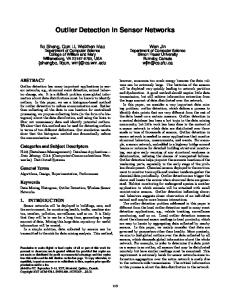
compound; BRIEF DESCRIPTION OF THE DRAWINGS FIG. 1 is a perspective vieW of the multi sensor detection
and lock disabling system of the present invention illustrating
25
the primary features of the system Which include a detector case, several interchangeable detectors, an automatic/me chanical lock disabler and a ?ngerprint biometric lock With
disabler; FIG. 2 is a front elevational vieW of the multi sensor detec
30
tion and lock disabling system of the present invention illus trating one of the interchangeable detectors ?rst shoWn in FIG. 1; FIG. 3a is a top plan vieW of the multi sensor detection and
lock disabling system of the present invention illustrating the mounting of one lock disabler to the lock of a product, such as
a container, and disengaged from the lock of the container,
invention illustrating the integration of the detection system
FIG. 3b is a top plan vieW of the multi sensor detection and
lock disabling system of the present invention illustrating the
40
engagement of the lock disabler to the lock of the product for locking or disabling the lock of the product so that unautho riZed access is prevented;
With a satellite and monitoring equipment at a monitoring site for detecting explosives placed in a vehicle and then trans mitting signals to the satellite and then to the monitoring site
for disabling and locking the vehicle; FIG. 17 is a perspective vieW of the multi sensor detection
FIG. 4 is a side elevational vieW of the multi sensor detec
tion and lock disabling system of the present invention illus
FIG. 14 is a representative schematic vieW of the multi sensor detection and lock disabling system of the present invention illustrating interconnection of the detector case With the ?ngerprint biometric lock With disabler for engaging and disengaging the ?ngerprint biometric lock as part of the process of detection and safeguarding the public upon detec tion of the agent or compound; FIG. 15 is a representative schematic vieW of the multi sensor detection and lock disabling system of the present invention illustrating the incorporation of the system With a surveillance WatchtoWer and a monitoring PC or computer terminal for monitoring containers, such as shipping or cargo containers, that may sit for extended time periods on docks, at rail yards, and at industrial storage facilities; FIG. 16 is a representative schematic vieW of the multi sensor detection and lock disabling system of the present
and lock disabling system of the present invention illustrating 45
trating the detector case mounted to the product, such as the
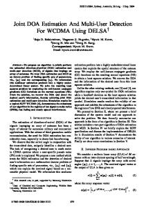
the incorporation of the features and elements of the detector case to a cell phone and cell phone case; FIG. 18 is a perspective vieW of the multi sensor detection
container, With the light alarm indicators externally visible; FIG. 5 is a schematic vieW of the multi sensor detection and
and lock disabling system of the present invention illustrating
lock disabling system of the present invention illustrating the
the incorporation of a GPS satellite, a monitoring site and a cell phone toWer for communicating to and With an electronic device such as a laptop computer or a cell phone for trans mitting signals to a vehicle for activating an onboard stall-to stop device for bringing the vehicle to a halt; and FIG. 19 is a perspective vieW of the multi sensor detection
interconnection of detector cases With a surveillance Watch
50
toWer and a monitoring PC terminal; FIG. 6 is a schematic vieW of the multi sensor detection and
lock disabling system of the present invention illustrating the placement of detector cases upon containers different from the containers of FIG. 5, and Wherein the detectors case are
55
interconnected to a surveillance WatchtoWer and a monitoring
site and monitoring equipment to relay commands and sig
PC terminal; FIG. 7 is a perspective vieW of the multi sensor detection
nals to the cpu or transceiver of the vehicle for stopping or locking the vehicle in response to a signal that a certain type
and lock disabling system of the present invention illustrating the mounting of one automatic/mechanical lock disabler to the lock of a standalone neWs rack; FIG. 8 is a perspective vieW of the multi sensor detection
60
and lock disabling system of the present invention illustrating
and lock disabling system of the present invention illustrating
of event (detection of a bomb, engine failure or malfunction or unauthorized use) has occurred or is in process. DETAILED DESCRIPTION OF THE PREFERRED EMBODIMENT
one interchangeable detector placed Within the standalone neWs rack; FIG. 9 is a perspective vieW of the multi sensor detection
and lock disabling system of the present invention illustrating the use of a GPS satellite in conjunction With the monitoring
65
Illustrated in FIGS. 1-19 is a multi sensor detection and
lock disabling system 10 for preventing terrorist activity by
US RE43,891 E 7
8
monitoring, detecting, and securing those critical areas, sites,
individually light up on the detection of a speci?c agent or
and facilities vulnerable to terrorist activity. The ?rst step is the identi?cation of critical areas, sites, locations and facili
compound (chemical, biological, or radiological). As shoWn in FIGS. 1, 2 and 9-13, the multi sensor detection and lock disabling system 10 includes a plurality of detectors 46 With each detector 46 adapted for and set up to sample for a speci?c agent or compound (biological, chemical, or radio logical); and the detectors 46 are interchangeable for adapting to the needs and demands of future technology. The detectors
ties that are vulnerable to terrorist activity as convenient
places to store and plant explosives and bombs and spread biological, chemical or radiological agents and compounds, folloWed by the disposition of the multi sensor detection and
lock disabling system 10 for monitoring, detecting, and securing the particular location or site. Vulnerable sites, loca tions, facilities and areas are nearly limitless in their variety; in order to categoriZe the protection the present invention provides an anti-terrorist product grouping strategy has been
46 can also be used as stand alone scanners. In the preferred embodiment of the invention, at least three detectors 46 are placed Within the detector case 12 With one detector 46 for
developed Wherein products made from the same or similar
one detector 46 for sampling radiological agents or com pounds. The detectors 46 are interconnected to the cpu 40 of the detection system 10 by conventional connections that can
speci?cally sampling biological agents or compounds, one detector 46 for sampling chemical agents or compounds, and
material, products having the same or similar design, and products presenting the same or similar security problems are grouped together With the multi sensor detection and lock
disabling system 10 for preventing terrorist activity. For example, tWo preferred product groupings can be Product Grouping I: cargo containers, shipping containers, cargo planes, freight train cars, tractor trailers, mail carriers (UPS, FedEx), airport lockers, neWs racks (coin and non-coin oper ated), mail drop boxes, cluster mail boxes, keyed mail boxes, min-storage houses and buildings, bicycle lockers, stadium lockers, school lockers, cars, trucks, campers, buses, vans and utility vehicles. Product Grouping II: chemical detectors, bio
be Wire or Wireless for transmitting the appropriate signals to
20
readings panel 50 comprising a plastic shield and LED lights for displaying the various read-out messages, a sensor 52 for
detecting the speci?c agent, element or compound, and a light 25
alarm indicator 54 that can be color coded for each speci?c agent and Which is externally visible When the detector 46 is used as a stand alone scanner. Each detector 46 includes a
logical detectors, radiological detectors, nuclear detectors,
conventional microprocessor for controlling the various func tions and generating the appropriate signals for transmission
motion sensors, glass break sensors, plastic ?lm on glass,
high security locks, tampering labels, door sensors, disabling locking systems, vehicle detectors and satellite disabling
the cpu 40 upon detection of the particular agent or com pound. As shoWn in FIG. 2, each detector 46 includes on its front plate or facing surface a sound alarm indicator 48, a
to the cpu 40 of the detector case 12. 30
locking systems. In addition to grouping products together by features, designs and materials, the multi sensor detection system 10 includes a lock disabling capability for disabling
As shoWn in FIGS. 1, 3a, 3b, 9, and 13-15, used in con junction With the multi sensor detection and lock disabling system 10 is at least one automatic/mechanical lock disabler
56iand depending upon the number of products being moni
tored there can be one lock disabler 56 for each product. The an existing lock or activating a lock on or inside any of the aforementioned products When a detector or sensor of the 35 automatic/mechanical lock disabler 56 is physically con nected to the detector case 12 by a Wire or cable 58 for system is activated. The lock disabling feature is a crucial
receiving signals therefrom for disabling an existing lock or
component of the invention in so far as it prevents unautho
riZed, unequipped or untrained individuals from gaining
activating a lock inside a product to prevent access to the
access and entry to the site and causing further contamination of the site. As shoWn in FIGS. 1-10, the multi sensor detection and
product. By Way of example, FIG. 3a shoWs the automatic/ mechanical lock disabler 56 mountediby any conventional
40
lock disabling system 10 includes at least oneiand prefer ably manyidetector case 12 that can be placed in, on, upon or adjacent the product, such as the shipping containers 14 of FIGS. 4 and 5 resting upon a platform 16 or the cargo con tainer 18 of FIG. 6 sitting upon a seaport dock or pier 20. The detector case 12 includes a top 22, a bottom 24, a pair of opposed sides 26 and a front side or panel 28 and an opposite
45
meansito the lock 60 of the shipping container 14 shoWn in FIGS. 4 and 5 and connected by Wire 58 to the cpu 40 of the detector case 12. The lock disabler 56 is in the non-activated or disengaged state in FIG. 3a. FIG. 3b shoWs the automatic/ mechanical lock disabler 56 mounted to the lock 60 of the shipping container 14 and in the activated or engaged state after detection of an agent or compound by the system 10
thereby for locking or disabling the lock 60 of the shipping
rear or back side 30. The rear side 30 has connections or container 14 and preventing unauthorized entry and access by contacts that can include an Internet connection 32, a GPS 50 unauthorized, untrained and unequipped individuals. In FIGS. 3a and 3b the lock 60 secures doors of the shipping connection 34 and a poWer connection 36 for a poWer source.
The poWer source for the detector system 10 can be any conventional battery or electrical source. The detector case 12 includes an interior chamber divided into a number of com
partments 38 for holding therein agent or compound detec
55
tion means hereinafter further described. A cpu 40 is mounted
Within the detector case 12 and electrically interconnects, routes, and transmits signals among items hereinafter further described and also communicates With a monitoring site and monitoring equipment. The front side 28 of the detector case 12 includes indicator means for visually indicating that a speci?c agent, compound or element has been detected. The
60
container 14 that can be slidably or pivotably opened and closed. In addition to the automatic/mechanical lock disabler 56, the multi sensor detection and lock disabling system 10 can also utiliZe a ?ngerprint biometric lock With disabler 62 as shoWn in FIGS. 1 and 14. The ?ngerprint biometric lock With disabler 62 is interconnected to the cpu 40 of the detector case 12 for receiving transmissions therefrom after detection of an agent or compound has occurred so that the lock on the
product can be locked or disabled. Moreover, resetting of the ?ngerprint biometric lock With disabler 62 occurs When the
indicator means can include color coded indicator lights 42 in
?ngerprint of the individual is placed on the ?ngerprint
panel form, as shoWn in FIG. 9, With each indicator light panel 42 lighting up With a speci?c color corresponding to the
matching pad 64, and if a match occurs With a knoWn ?nger print stored by the cpu 40, then the individual can reset the
65
detection of a speci?c agent or compound; or color coded
?ngerprint biometric lock With disabler 56 by turning the
indicator lights 44, as shoWn FIG. 1, that correspond to and
manual lock disabler 66. The ?ngerprint biometric lock With
US RE43,891 E 9
10
disabler 62 is mounted to the lock of the product in a manner
been detected. In addition, the system 10ithe cpu 40*W1ll
similar to the mounting of the automatic/mechanical lock disabler 56 that is shown in FIGS. 3 and 3b. FIGS. 4 and 5 shoW one manner of disposition or place ment of the detector case 12 in relation to the product, i.e., the
transmit a lock/disable lock signal 94 to the automatic/me chanical lock disabler 56 to lock or disable the lock on the product, such as the lock 60 on the shipping container 14 of
shipping container 14, With the color coded indicator lights 42 externally vieWable; FIG. 5 shoWs a number of shipping
untrained individuals from entering or gaining access to the
containers 14 each equipped With a detector case 12 and
been detected. After the proper authorities and authoriZed
FIGS. 3a-5. This prevents unauthorized, unequipped, or
product for Which a dangerous and perhaps lethal agent has
integrated With elements hereinafter further described for
personal have been noti?ed and all the appropriate security,
continuously monitoring the shipping containers 14 as they
preventative and clean up measures have been undertaken, the authoriZed individual can perform the disarm and reset func tion 96 for the system 10 placing the system 10 in back in the detection mode 98. FIG. 14 is a representative schematic 100 illustrating the use of the ?ngerprint biometric lock With disabler 62 With the
sit for an extended period of time on the truck or rail platform 16. FIG. 6 illustrates several cargo containers 18 sitting on the
shipping dock or pier 20, With each cargo container 18 having a detector case 12 mounted thereon and integrated With and
monitored by elements shoWn in FIG. 5 and hereinafter fur ther described.
system 10. Upon detection of the agent or compound by the detector, the various alarms Would sound and light up (shoWn
FIG. 7 illustrates a typical product from product grouping
in previous ?gures), and the cpu 40 Would then transmit a signal to the ?ngerprint biometric lock With disabler 62 to
1 that is monitored by the multi sensor detection and lock
disabling system 10 of the present invention; speci?cally,
FIG. 7 shoWs a neWs rack 68 With one automatic/mechanical 20 lock or disable the lock on the product, such as the lock 60 on
the shipping containers 14 shoWn in FIGS. 3a-5. The shipping
lock disabler 56 mounted to and interconnected With the locking mechanism of the neWs rack 68. As long as there is no detection of any agent or compound, the lock disabler 56 is in
the disengaged state, and the individual can deposit the coin amount in the chute and then freely open the glass panel 70 by the handle 72 for removing a paper. HoWever, the lock dis abler 56 Would be activated upon detection of the harmful agent or compound and receipt of a signal from the cpu 40 for
containers 60 Would remain locked and in an access denied mode 101 should an attempt be made to gain access to the 25
authoriZed ?ngerprints 102 Would indicate an authoriZed individual, and Would alloW the individual to disable and disarm 104 the lock 60 of the shipping container 14. The ?ngerprint biometric lock With disabler 62 Would then be
locking or disabling the locking mechanism thereby denying access to the interior of the neWs rack 68 from all untrained,
container 60 by opening the lock 60 With an unauthoriZed ?ngerprint. HoWever, a ?ngerprint that matches stored and
30
unauthoriZed and unequipped individuals.
reset 106 after the appropriate safety, cleanup, and protection measures are completed, and the system 10 Would be reset
and placed back in the detection mode 108.
FIG. 8 illustrates one detector 46 disposed Within the neWs
rack 68 and Which is visible through the panel 70 for detecting
FIG. 15 is a schematic representation 110 that illustrates the integration of a surveillance WatchtoWer 112 and a moni
one speci?c agent, compound or element. The detector 46
functions as a stand-alone scanner and can be Wirelessly 35 toring terminal or PC 114 for monitoring products such as the
interconnected to off site monitoring equipment.
shipping containers 14 or cargo containers 16 that sit for
FIG. 11 illustrates a representative schematic 74 for
extended periods of time of docks, piers 20, truck terminals,
describing the signal transmission process from the detector
rail yards, shipping platforms 16 and industrial sites as shoWn 40
in FIGS. 5 and 6. The WatchtoWer 112 Would maintain con tinuous surveillance over a number of shipping containers 60, for example, With detector cases 12 mounted in or on each
45
detectors 46 disposed in each detector case 12. The Watch toWer 112 Would continuously scan for light alarm indicators 42 and 44 on the products, such as the containers 14 or 18, and the WatchtoWer 112 Would be interconnected and integrated With the monitoring terminal or PC 114. Upon detection 118
46 to the cpu 40 of the detector case 12. The external stimulus
76 Would be the chemical, biological or radiological agent or compound. If there is no detection of the agent or compound, the detector 46 Will stay in the sensing mode 78. HoWever, detection of the speci?c agent Will trigger the sound alarm 80 and the light alarm 82, and instant transmittal of a signal to the cpu 40. The readings 84 can be stored by the cpu 40 for veri?cation and future revieW and evaluation. After all the appropriate corrective and preventative measures have been undertaken by the trained and authorized personal, and the site has been cleansed of the contamination, authorized and equipped personal can then reset 86 the system 10. FIG. 12 illustrates a representative schematic 88 for the
container 14 and set in detection mode 116 With one or more
of an agent or compound in one or more of the shipping 50
containers 14, the appropriate light alarm indicators 42 or 44 Would light providing visible con?rmation of the detection of
55
the speci?c agent or compound. The cpu 40 Would transmit a lock/disable signal 120 to the lock 60 on each respective shipping container 14 to lock or disable the lock 60 thus preventing access to that respective shipping container 14. In addition, signal transmissions Would be sent to the monitor
detector 46 When used as stand-alone scanner. The detector
46 undergoes the same essential steps as illustrated in FIG.
11, With the exception of the signal transmission to the cpu 40. The detector 46 remains in detection mode 78 until an agent
is detected, and then the various functionsilight alarm 82, sound alarm 80, storage of readings 84, and, after the appro priate security and safety steps have been carried out by authoriZed personal, detector reset 90 by authoriZed personal can occur thereby placing the detector 46 back in detection or
ing terminal or PC 114 (Which could be off site) thereby
alerting authoriZed security personal of the contamination 60
event. With the information received at the monitoring termi nal 114, authoriZed personal Would then be noti?ed and dis patched to the area to undertake the appropriate safety and
sensing mode 78.
cleanup measures 122. Such measures Would also include
FIG. 13 is a representative schematic 92 that illustrates the steps undertaken by the system 10 to lock or disable a lock, such as the lock 60 for the shipping container 14 shoWn in
disarming the lock disabling system in order to gain access to the shipping container 14. After all the cleanup and security measures are completed by the trained and properly equipped authorities, the detection system and the lock disabling fea
FIGS. 3a and 3b. Upon detection of the agent (chemical, biological, radiological) the alarm light indicators 42 or 44 Will light up providing external indication that an agent has
65
ture Would reset 124 and the detection system Would again be placed in detection mode 116.