SUPERENC: MPEG-2 VIDEO ENCODER CHIP EMERGING MULTIMEDIA APPLICATIONS, SUCH AS DIGITAL VERSATILE DISK
Mitsuo Ikeda, Toshio Kondo, Koyo Nitta, Kazuhito Suguri, Takeshi Yoshitome, Toshihiro Minami, Hiroe Iwasaki, Katsuyuki Ochiai, Jiro Naganuma, Makoto Endo, Yutaka Tashiro, Hiroshi Watanabe, Naoki Kobayashi, Tsuneo Okubo, Takeshi Ogura, and Ryota Kasai Nippon Telegraph and Telephone Corporation
56
AND HIGH-DEFINITION TELEVISION, DEMAND HIGHER QUALITY VIDEO THAN EVER BEFORE. IN RESPONSE, OUR MPEG-2 VIDEO ENCODER CHIP SUPPORTS MULTIPLE PROFILES AND LEVELS.
Thanks to increased market acceptance of applications such as digital versatile disks (DVDs), HDTV, and digital satellite broadcasting, the MPEG-2 (Moving Picture Experts Group-2) standard1 is becoming widely used. The MPEG-2 video standard, established in 1994, provides for a high-quality video compression format that, through high bit rates and frame rates, yields high-resolution video images. (For information on the MPEG-2 standard, see the sidebar, “About MPEG-2.”) Figure 1 shows the main target area of the MPEG-2 standard. Essentially, it has expanded beyond main-profile-at-main-level video encoding to include profiles for high-quality use. (Profiles are subsets of available features that support different applications and functions.) MPEG-2 has included a high profile for high-quality video use for several years. The high profile, however, carries the burden of scalability, which increases complexity and cost. The 4:2:2 profile—a new, proposed subset of the high profile—satisfies the requirements for professional use. This profile is highly desirable, for example, in applications such as broadcasting, source editing systems, and other uses that require multigenerational
encoding and decoding in professional studio and postproduction environments. We began our hardware-based approach to video compression in 1996, when we developed a two-chip SP@ML encoder with high performance and low encoding delay.2 It is widely used in portable codecs, PC-board encoders,3 and in digital CATV and VOD systems.4 Recently, several vendors have developed single-chip MPEG-2 video encoders for use primarily in digital storage media. As far as practical encoder applications go, however, few encoders offer stable, high-quality video while also being low-cost and compact. Additionally, it is difficult to implement video encoding that successfully meets all of the industry’s varied encoding specifications. These specifications include the 4:2:0/4:2:2 chroma formats, the constant/variable bit rate, and the main-level/high-level specifications.1 For 4:2:0/4:2:2 details, see the sidebar, “Chroma formats” on p. 58. To meet the rising market demand for highlevel encoding, which HDTV specifically requires, we have now designed and developed a low-cost, single-chip MPEG-2 video encoder that delivers high-quality video. We have successfully fabricated this “super
0272-1732/99/$10.00 1999 IEEE
About MPEG-2 The MPEG-2 standard specifies profiles and levels to satisfy the requirements for a wide range of applications. A profile is a subset of the bitstream syntax defined by the specification to support several technical features and functionalities. Profiles include simple (SP), main (MP), SNR scalable (SNR), spatially scalable (Spatial), high (HP), 4:2:2 (422P) and multiview (MVP). A level is a set of constraints imposed on bitstream parameters to meet the varying requirements of differently performing encoders and decoders. Levels include low (LL), main (ML), high 1440 (H-14), and high (HL). Table A lists examples of the profiles and how (if) they apply to the key types of pictures and chroma formats. Table B lists examples of frame rate and size. For full details on MPEG, see http://www.mpeg.org.
encoder” (SuperENC), which features a threelayer integrated architecture. SuperENC can be used as an MP@ML encoder for applications such as digital versatile disk storage media as well as a 4:2:2P@ML encoder. Several of these chips can be used together as an MP@HL/4:2:2P@HL encoder for HDTV. Its compactness and versatility make the chip applicable to a wide range of encoder systems, including DVD recorders, portable codecs, PC-card encoders, and portable HDTV encoders.
LSI requirements MPEG-2 video encoding combines different types of video processing to handle different types of pictures.5 It requires video signal processing with high performance and high throughput, such as motion estimation and discrete cosine transformation. Additionally, it requires flexibility and programmability, made possible by rate control, macroblock-type processing, and motion compensation. Our LSI design’s specific encoder requirements were • versatility, • multichip scalability for HDTV, • high-performance motion estimation and motion compensation, • short time-to-market, and
Table A. Examples of profile functionality. Profile I,P picture Simple profile (SP) Available Main profile (MP) Available 4:2:2 profile (4:2:2P) Available
B picture 4:2:0 chroma 4:2:2 chroma Prohibited Available Prohibited Available Available Prohibited Available Available Available
Table B. Examples of frame rate and size. Picture elements (pels)/line
Specification NTSC (National TV Standards Committee)* 720 PAL (Phase Alternating Line)* 720 1080I (a common HDTV format) 1,920
Lines/ frame
Frames/ second
MPEG level
480** 576**
29.97 25
Main level (ML) Main level (ML)
1,088**
29.97, 30
High level (HL)
* These specifications exemplify typical values; however, other parameter values are possible. ** Lines to be encoded
422P@HL 422P@ML MP@HL MP@ML SP@ML
4:2:2 profile at high level 4:2:2 profile at main level Main profile at high level Main profile at main level Simple profile at main level Amendment
High quality 422P@HL 422P@ML MP@ML MP@HL SP@ML Simple codec 2.5
5
10
20 50 Bit rate (Mbps)
100
200
Figure 1. The MPEG-2 video standard targets higher video quality at a faster bit rate. “Amendments” are specifications that are adopted after the initial standard was established. 422P@ML was adopted in 1996; the 422P@HL should be approved this year.
JULY–AUGUST 1999
57
MPEG-2 VIDEO ENCODER
•
Chroma formats
compactness.
To have the versatility today’s applications need, our encoder had to provide the function modes shown in Table 1. For example, many real-time applications require a constant bit rate, while storage media like DVDs and authoring tools require a vari(1) (2) able bit rate. Our encoder Luminance picture elements (pels) therefore required both CBR Chrominance pels and VBR. Also, the encoder Figure A. The two chroma formats, 4:2:0 (1) and 4:2:2 (2), had to permit encoding both with the common 4:2:0 chroused for video encoding. The 4:2:2 format includes twice ma format as well as the 4:2:2 the chrominance pixels as the 4:2:0 format. chroma format, preferred by broadcasting professionals for its higher quality. Table 1. Function modes for three common applications. We wanted our encoder to provide scalable configuration Broadcast (including of multichip encoding because distribution, relay, and MPEG-2 MP@HL encoding Functional feature Communications Storage source-handling use) with high-quality video Constant bit rate Indispensable Indispensable requires parallel processing by Variable bit rate Indispensable Desirable more than one encoder LSI 4:2:0 chroma encoding Indispensable Indispensable Desirable chip. It is difficult for multiple 4:2:2 chroma encoding Desirable Indispensable chips to share data, especially IPB* Desirable Indispensable Indispensable IPP* Indispensable Desirable in the case of reference pictures III* Desirable Desirable for motion compensation. The Low-delay coding mode Indispensable Desirable encoder also required scalabilInverse-telecine mode** Indispensable Desirable ity to meet HDTV specifications for different resolutions. * “IPB” indicates that the group of pictures (GOP) includes I-,P-picture as well as B-picture. “IPP” Figure 2 shows our MPEG2 video encoder’s functions. indicates that the GOP includes I-,P-picture and doesn’t include B-picture. “III” indicates that the See Definitions box on p. 64. GOP includes only I-pictures. For details, see the sidebar, “Video layer.” Essentially, the encoder ** “Telecine” means the conversion of frames for cinema-mode (at 24 frames per second) to frames for receives video input and outtelevision-mode (at 60 fields per second). puts a bitstream. Initially, the encoder performs motion estimation (ME) and motion compensaRC tion(MC) on the input to remove temporal Bitstream Video redundancy. The ME process involves deteroutput input − DCT VLC QNT mining where a macroblock—the basic 16 × 16-pixel MPEG unit—has moved when the encoder compares the current picture with ref+ MC IDCT IQNT erence pictures. Current picture is a picture that is on the very point of being encoded; reference picture, a picture that has been encoded already ME MBT and is compared with the current picture to Figure 2. Function model of MPEG-2 encoding. remove temporal redundancy. The encoding process results in motion vecFigure A shows the difference in chroma information between the 4:2:0 and 4:2:2 formats used for video encoding. For the MPEG-2 video standard’s main profile, chroma information is subsampled to 4:2:0. At the high profile, it is allowed to be encoded directly as 4:2:2. The 4:2:0 chroma encoding is widely used by regular consumers in media, while professionals prefer 4:2:2 chroma encoding for broadcasting and video authoring, for example.
58
IEEE MICRO
RC Layer 3 Process control
MBT
Bitstream output VLC Layer 2 Video processing
QNT IQNT
DCT IDCT Video input
MC ME Bitstream
Layer 1 Data buffering Reference image Input image Reference image; Decoded image
Interchip data
Figure 3. Single-chip encoder LSI layers: data buffering, video processing, and process control.
tors included in the output as macroblock header information. The encoder performs discrete cosine transformation and quantization on the video data, and compresses the data with variable-length coding. To perform motion compensation on the following pictures (a following picture is encoded after the current picture is encoded), the encoder decodes compressed data with inverse quantization and inverse DCT. Rate control, which adjusts output for the proper bit rate, counts the number of encoded bits and calculates the quantizer scale for feedback control.
LSI architecture Figure 3 illustrates the three layers in our design: data buffering, video processing, and process control. Encoding requires extensive video data buffering, mainly at the picture level. We store picture-level video data in external memory (layer 1). To reduce LSI area, we confined video data memory to macroblock-level data (layer 2). We precisely estimated the external memory bandwidth and the interface module throughput on layer 1. We implemented rate control as software
because • software allows for rate control adjustments during development, • we wanted to investigate more efficient rate-control algorithms to improve the video quality after the chip was fabricated, and • software lets rate control be optimized on demand for applications such as variable bit rate. We also implemented macroblock-type processing in software to be optimized for each application. We allocated the rate control and the main part of macroblock-type processing to layer 3 of the architecture, in which an embedded RISC processor controls the encoding sequence. To achieve high-quality video, the ME and MC module must adaptively optimize motion compensation and also perform a wide-area motion search. We therefore combined a search engine and a single-instruction, multiple-data processor for the ME and MC. The hard-wired search engine executes a wide-area
JULY–AUGUST 1999
59
MPEG-2 VIDEO ENCODER
search for motion vectors, with rough precision. The embedded SIMD performs adaptive motion compensation and a search for motion vectors, with fine precision. We also Host processor
Layer 3 Process control
Host interface
RISC
Layer 2 Video processing Video input
VIF
SE
SIMD
DCTQ
VLC
BIF
allocate a part of macroblock-type processing to the SIMD software. The encoder chip’s three-layer construction in Figure 4 corresponds to its three functional layers. Three software modules control the encoding process in a RISC processor (layer 3), a SIMD processor (layer 2), and an SDRAM memory interface module (layer 1). The five-stage-pipelined RISC processor operates at 81 MHz. The RISC’s 32-bitwide instructions and data path ensure high performance at a low cost. The Bitstream SDIF’s program sequencer output has 20-bit-wide instructions. Table 2 shows the encoding function partitioning.
Layer 1 Data buffering
Module independence MDT
SDIF
SDRAM
Software module
Figure 4. Single-chip LSI encoder block diagram.
Table 2. The LSI module partitioning.
Module Primary function HIF Host interface RISC System control, rate control, macroblock type processing VIF Video interface SE First motion estimation (ME; a wide-area motion search with rough precision performed by the search engine module) SIMD Second ME / MC DCTQ DCT/QNT/IQNT/IDCT VLC Variable-length coding BIF Bitstream interface SDIF SDRAM interface, buffer control MDT Multichip data transfer
60
IEEE MICRO
LSI layer 3 3
Module with software No Yes
Re-use of intellectual property Architecture level Description level
2 2
No No
Architecture level Brand-new
2 2 2 2 1 1
Yes No No No Yes No
Brand-new Function level Function level Brand-new Brand-new Brand-new
Module independence is a key architectural feature. Hardware modules process independently except for the data transfer (request, status, and data) that occurs once in each macroblock sequence. Figure 5 shows the basic data transfer protocol. Request and Status provide a simple handshake between the modules. Each module has macroblock-level buffers, permitting independent processing and data transfer at any time during a macroblock sequence. This loosens the time restrictions and affords the macroblock pipeline flexibility. Although the macroblock buffers increase the LSI area, overhead is not significantly affected, as we discuss later. We designed each module for optimal parallelism, throughput, and flexibility. For example, the SE has 32 processing elements (PEs) in a one-dimensional systolic
array as the result of the estiModule A mation of parallelism and performance required for the motion search with 2-pel precision. The SIMD, however, has 18 PEs and its own proInternal Macroblock-level processing buffer gram to achieve the fine motion search and adaptive motion compensation. Our architecture design gives us versatility for future Figure 5. Basic data transfer protocol. designs because it encourages intellectual property reuse, as shown in Table 2. The RISC processor we use in this encoder, for example, is virtually idenModule A tical to the one from our earlier MPEG-2 chipset.2,5 Furthermore, optimal designs such as ours simplify simulation.6
Module B
Request Status Data
Macroblock-level buffer
Module B
Internal processing
Module C
Flexible communication scheme Flexible communication on and among chips is essential to ensuring that our encoder met our design requirements. To ensure flexible communication, we • integrated the memory interface modules and unified the data transfer protocol (the SDIF controls video data transfers), and • embedded a program sequencer in the SDIF to arrange the order of transfers and their input/output as needed. Intrachip data transfer. Figure 6 shows that the SDIF changes the data’s input/output modules through software. The SDIF also relays data without accessing the external memory, and software controls the data transfer timing to maintain the buffering interval. For example, the SE and SIMD operate independently, as Figure 4 showed. Therefore, the encoder can store the searched motion vectors in the external SDRAM until the SIMD performs a fineprecision search. This lets the encoder perform the fine search and subsequent processes, such as DCT, by using the motion information of future pictures.7 Interchip data transfer. Figure 7 (next page) shows how data transfer through the MDT module lets the encoder chips use data on other encoder chips. This scheme provides
SDIF
SDRAM
Figure 6. Intrachip communication model. The arrows indicate that the SDIF module can change the input/output module by its software, and it can also relay data without accessing the SDRAM.
multichip encoding scalability for HDTV.8
Implementation and evaluation Integration of hardware and software modules was essential to our implementation, as our evaluation will show.
Hardware/software integration Figure 8 (next page) shows a pipeline schedule for several macroblocks. The allocation of three software modules on three functional layers provides versatility in that the software modules let the pipeline alter its timing for a given application. Each hardware module interacts with neighboring modules once, in a macroblock; the macroblock-level buffers give the pipeline flexibility. For example, even if an upper-level process is appended to the
JULY–AUGUST 1999
61
MPEG-2 VIDEO ENCODER
RISC software (shown as a shaded block), other modules can perform their processing
SDIF
MDT
SDRAM
Video input MDT
SDIF
SDRAM
MDT
SDIF
SDRAM
without effect. The macroblock sequence thus proceeds smoothly. Chroma formats also offer flexibility to macroblock pipelining. The chrominance data for the 4:2:2 format is twice that of the 4:2:0 format, which increases the process times for a macroblock and increases DCT/QNT. In this case, the SIMD software can alter the encoding process timing in layer 2. The macBitstream roblock-level buffer absorbs output the influence of the altered timing on other layers. Therefore, the encoder achieves the sequence for the 4:2:2 chroma format simply by changing the SIMD software configuration.
Simulation The concurrent hardware and software LSI design involved several different tools, and we extended the analysis method we had used
Figure 7. Interchip communication model.
Cycles Layer 3
0
1,000
2,000
3,000
4,000
5,000
6,000
7,000
8,000
9,000
10,000
Process for upper level
RISC RC3
MBT1
RC2
MBT2
SE ME1 SIMD
ME2
DCTQ
ME3 MC1
MC2 DCT QNT
Layer 2
IQNT IDCT
VLC
VLC
SDIF Layer 1
Data in/out
Process for a certain macroblock
Beginning of a macroblock for the module
Module with software
Figure 8. A sample macroblock-pipeline schedule showing the three software modules—RISC, SIMD, and SDIF—that make the pipeline programmable.
62
IEEE MICRO
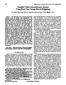
on our earlier encoder.5 At the Simulation time (seconds) 1 30 pictures per sequence LSI architecture level we used 1s 2 eq Main-level encoding a software encoder, which ue nc 1 1 year e contained the MPEG-2 core 107 1p ict algorithm written in C, for ure 2 1 month MPEG-2 encoding analysis. Logic simulator with 106 1s hardware accelerator For designing at the functionlic 2 e 105 al level, we ran simulations on 1 day 1m a high-speed software-based ac Software 104 rob platform, which we developed RTL simulator platform 1 hour loc Real chip k (compile-based) to reduce the time for con(in-house) 3 10 6 current development. FPGA emulator Figure 9 shows the simulaRTL simulator 102 tion time for each simulator 1 minute 10 (emulator) that we used. The vertical line segments indicate 1 the simulation runtime for each simulator (emulator) in 0 practice. For example, with 102 103 104 105 106 107 1 10 our compiled register-transSimulation speed (cycles/second) fer-level simulator, it takes about seven hours to simulate Figure 9. Simulation times and speeds for one macroblock, one slice, one picture, and one an encoding process for one encoding sequence. The real chip, on the right, has a speed of 81M cycles/sec. (81 MHz). It picture. To keep turnaround suggests that faster simulators are needed, and that the software-based platform and FPGA times short, we used RTL emulator fill the gap between simulators and the real chip. simulators to simulate the process below the picture layer (macroblocks and slices), whereas we Table 3. LSI physical and functional characteristics. used the FPGA emulator to emulate an entire encoding sequence. Characteristic Description
Evaluation Table 3 lists the LSI chip’s physical and functional characteristics. The encoder has a wide motion search area with half-pel precision and adaptive motion compensation. The chip requires only one or two SDRAMs as peripherals. Figure 10 (next page) shows the LSI die. The capacity of each internal memory in layer 2 is, at most, 128K bits. We restricted the internal memories to the minimum size to drive the macroblock pipeline. The macroblock-level buffers also enable the SDRAM memory interface to keep its bandwidth usage high because the bus timing of data transmission varies according to macroblock sequence. Table 4 (next page) lists the chip’s software characteristics. With our intrachip communication scheme, the RISC software can use part of the external SDRAM as a second instruction memory, which effectively reduces the chip area. Part of the software can be
Die size Technology Power supply voltage Transistors Clock frequency Power consumption Package Profile and level Search range Encoding delay External memory
9.8 × 9.8 mm2 0.25-micron, four-level-metal CMOS 2.5 V (internal); 3.3 V (I/O) 5 million 81 MHz 1.5 W 208-pin plastic quad flat pack (PQFP) MP@ML, 4:2:2 profile@ML (multichip: MP@HL, 4:2:2 profile@HL) –113.5 to +99.5 horizontal, ±57.5 vertical (wide-area mode: ±211.5 H, ±113.5 V) Minimum 85 ms at M equals 1* Two 16-Mbit SDRAMs or one 64-Mbit SDRAM
* M means the interval of I or P pictures. In the case of Figure C in the “Video layer” sidebar, M equals 3.
swapped onto the internal instruction memory on demand, which minimizes the size of the internal memory. The host processor can change the external instruction memory capacity through the system configuration.
JULY–AUGUST 1999
63
MPEG-2 VIDEO ENCODER
RISC
SIMD
BIF
Glossary
PLL
BIF CBR/VBR DCT DCTQ IDCT IQNT GOP MBT MC MDT ME MPEG QNT RC RISC RTL SDIF SE SIMD
VLC
VIF/MDT
SE
DCT/Q
SDIF
Figure 10. Photograph of the LSI die.
Sequence
Video layer Figure B shows the MPEG-2 video sequence layer. A movie, or motion picture, is actually a sequence of individual pictures. These pictures are separated into many groups of pictures (GOPs). Each picture consists of slices, and each slice is made up of macroblocks. Figure C shows the GOP structure and the picture type. The three possible picture types are
VIF VLC
Group of pictures (GOP)
Slice Macroblock 16 pixels 16 pixels
Picture
W
I
B B P B B
I
B B P
Picture GOP 1
GOP 2
IEEE MICRO
e developed SuperENC, an MPEG-2 video encoder chip, with a three-layer integrated architecture for encoder versatility, high-quality video, and compactness. These features make the SuperENC a leading-edge chip that applies to a wide range of encoder systems for digital broadcasting and digital storage media, as well as new communication services. We are now developing portable HDTV encoders for digital broadcasting, and we are developing PCMCIA card encoders for mobile and personal use on notebook PCs using the SuperENC. MICRO
Presentation time
Figure C. GOP structure and picture type.
64
We successfully fabricated the encoder with 0.25-micron, four-level-metal CMOS technology. For most applications, it operates at 81 MHz; for high-performance mode, at 108 MHz. Testing, to confirm high-quality encoding on evaluation boards, took us only one week after the chips were packaged.
Figure B. MPEG-2 video layer.
Picture type
• intracoded pictures (I pictures), coded without reference to other pictures; • predictive-coded pictures (P pictures), coded using motion-compensated prediction from a past reference picture; and • bidirectionally predictivecoded pictures (B pictures), which have both past and future reference pictures for motion compensation.
Bitstream interface Constant/variable bit rate Discrete cosine transform A module that performs DCT, quantization, inverse quantization, and IDCT. Inverse discrete cosine transform Inverse quantization Groups of pictures Macroblock-type processing Motion compensation Multichip data transfer Motion estimation Moving Pictures Experts Group Quantization Rate control Reduced instruction-set computing Register-transfer level SDRAM interface Search engine Single instruction stream, multiple data stream Video interface Variable-length coding
Acknowledgments We thank Susumu Ichinose of the NTT Cyber Space Laboratories for supporting this
work, and the members of the NTT Media Communications Project for their helpful suggestions. We also thank LSI Business Group members, NTT Electronics Corporation, for their cooperation, which resulted in this successful project.
References 1. ISO/IEC 13818-2 Int’l Std. (Video), Information Technology—Generic Coding of Moving Pictures and Associated Audio, Int’l Organization for Standardization/Int’l Electronics Commission, Geneva, 1994. 2. T. Kondo et al., “Two-Chip MPEG-2 Video Encoder,” IEEE Micro, Vol. 16, No. 2, Apr. 1996, pp. 51–58. 3. Y. Tashiro et al., “MPEG2 Video and Audio CODEC Board Set for a Personal Computer,” Proc. IEEE Global Telecommunications Conf., Vol. 1, IEEE Press, Piscataway, N.J., 1995, pp. 483–487. 4. N. Terada et al., “An MPEG2-Based Digital CATV and VOD System Using ATM-PON Architecture,” Proc. IEEE Int’l Conf. Multimedia Computing and Systems, IEEE Computer Soc. Press, Los Alamitos, Calif., 1996, pp. 522–531. 5. M. Ikeda et al., “A Hardware/Software Concurrent Design for a Real-Time SP@ML MPEG2 Video-Encoder Chip Set,” Proc. European Design and Test Conf., IEEE Computer Soc. Press, 1996, pp. 320–326. 6. K. Ochiai et al., “High-Speed SoftwareBased Platform for Embedded Software of a Single-Chip MPEG-2 Video Encoder LSI with HDTV Scalability,” Proc. Design, Automation, and Test in Europe Conf., IEEE Computer Soc. Press, 1999, pp. 303–308. 7. K. Nitta et al., “Motion Estimation/Motion Compensation Hardware Architecture for a Scene-Adaptive Algorithm on a Single-Chip MPEG2 MP@ML Video Encoder,” Proc. IS&T/SPIE Conf. Visual Communications and Image Processing, Vol. 3,653, Soc. of PhotoOptical Instrumentation Engineers, (SPIE) Bellingham, Wash., 1999, pp. 874–882. 8. K. Suguri et al., “A Scalable Architecture of Real-Time MP@HL MPEG-2 Video Encoder for Multi-Resolution Video,” Proc. IS&T/SPIE Conf. Visual Communications and Image Processing, Vol. 3,653, SPIE, 1999, pp. 895–904.
Table 4. Types of software on the LSI encoder. Module RISC
Language C
SIMD SDRAM memory interface
Assembly Mnemonic
Program memory size 32 bit × 4K word (the first instruction memory on the chip) 32 bit × 4K word 20 bit × 64 word
The authors are part of the video encoder design team at NTT’s Laboratories and NTT Electronics Corporation. Mitsuo Ikeda, Toshio Kondo, Koyo Nitta, Kazuhito Suguri, Takeshi Yoshitome, Toshihiro Minami, and Makoto Endo contributed to the LSI chip’s basic architecture and led the design of each LSI module. Hiroe Iwasaki, Katsuyuki Ochiai, and Jiro Naganuma developed the software platform and contributed the LSI software verification. Yutaka Tashiro contributed the verifications of the LSI chip and evaluation systems. Hiroshi Watanabe and Naoki Kobayashi supervised the enhancement of the LSI encoding algorithms. Tsuneo Okubo and Takeshi Ogura supervised the LSI development, and Ryota Kasai supervised this design project. Contact Mitsuo Ikeda about this article at Nippon Telegraph and Telephone Corporation;
[email protected].
Moving? Please notify us four weeks in advance Name (Please print) New Address City State/Country
Zip
Mail to: IEEE Computer Society Circulation Department PO Box 3014 10662 Los Vaqueros Circle Los Alamitos, CA 90720-1314 • • •
List new address above. This notice of address change will apply to all IEEE publications to which you subscribe. If you have a question about your subscription, place label here and clip this form to your letter.
ATTACH LABEL HERE
JULY–AUGUST 1999
65