Modified Model Reference Adaptive Control Algorithm to Improve System Robustness
Lin Yang
A dissertation submitted to the University of Bristol in accordance with the requirements of the degree of Master of Science in the Faculty of Engineering, Department of Mechanical Engineering.
September 30, 2004
Word Count: 26000
Abstract
Adaptive control systems have a wide range of applications in mechanical and electrical engineering due to their versatility and relative ease of application. However stability and robustness problems with adaptive control algorithms have limited the extent to be used in practical situations. The research in this thesis focuses on the first order model reference adaptive systems (MRAC) and Minimal Control Synthesis (MCS) in the continuous formulation. The work firstly is concerned on understanding the gain dynamics during adaptation by analysing the system as a set of nonlinear ordinary differential equations. Using techniques from dynamical systems theory, we then study the phenomena of gain ‘wind-up’ in the system state space. We present a modified algorithm to eliminating this phenomenon by altering the structure of the controller, with the aim of improving stability and robustness for practical use. The modified algorithm is firstly tested on the MCS system in a special case of unity step input. Theoretical proof and simulation results show the gain ‘wind up’ is eliminated by this modified structure. After this, the modified algorithm is tested in MCS system with a general input case. The MRAC system is studied followed by the MCS system. It shows that the MRAC system (based on the Lyapunov rule) has the same problem of gain ‘wind up’ in the presence of noise. By using the same idea, we modified the MRAC structure by removing the zero eigenvalue of Jacobian matrix. It is proved theoretically and by simulation results that the modified MRAC algorithm eliminates the gain ‘wind up’, and system gives robust behaviour due to noise. Keywords: Model reference, Adaptive control, Nonlinear dynamics, Gain wind up, Global stability, Robustness.
Page 1
ACKNOWLEDGEMENTS I would like to thank all those at Mechanical Engineering Department and Engineering faculty who had help me carry out my research in the past year. Particular I would like to thank my advisers Dr. Simon Neild and Dr. David Wagg for their guidance and support throughout this period. I would also like to thank my colleagues in the Automatic Control Laboratory for their friendship and thought provoking discussion during my research. Finally I would like to thank my parents for their support and understanding in my further study, and all my friends helping and supporting me during this period.
Modified Model Reference Adaptive Control Algorithm to Improve System Robustness
L. Yang
Page 2
AUTHOR’S DECLARATION
I declare that the work in this dissertation was carried out in accordance with the Regulations of the University of Bristol. The work is original except where indicated by special reference in the text and no part of the dissertation has been submitted for any other degree. Any views expressed in the dissertation are those of the author and in no way represent those of the University of Bristol. The dissertation has not been presented to any other University for examination either in the United Kingdom or overseas.
SIGNED:
Lin Yang September 30, 2004
Modified Model Reference Adaptive Control Algorithm to Improve System Robustness
L. Yang
CONTENTS
Page i
Contents 1 Introduction 1.1
1
Overview of model reference adaptive control and minimal control synthesis . . . . . . . . . . . . . . . . . . . . . . . . . . . . . . . . . .
1
1.1.1
Model reference adaptive control . . . . . . . . . . . . . . . .
2
1.1.2
MCS Adaptive Control . . . . . . . . . . . . . . . . . . . . . .
3
1.2
Dynamical system approach . . . . . . . . . . . . . . . . . . . . . . .
3
1.3
Lyapunov stability theory and global stability approach . . . . . . . .
4
1.4
Objectives of work . . . . . . . . . . . . . . . . . . . . . . . . . . . .
5
1.5
Thesis overview . . . . . . . . . . . . . . . . . . . . . . . . . . . . . .
6
2 Theoretical formulation for Model reference adaptive control algorithm 8 2.1
Theoretical formulation for MRAC based on Lyapunov rule . . . . . .
8
2.2
Theoretical formulation for MCS . . . . . . . . . . . . . . . . . . . . 10
2.3
Parameters chosen for MRAC and MCS system . . . . . . . . . . . . 15
2.4
Geometry of phase space . . . . . . . . . . . . . . . . . . . . . . . . . 16
3 Using error dynamical approach to analyse standard model reference adaptive control algorithm 18 3.1
Set up dynamical system for MCS . . . . . . . . . . . . . . . . . . . . 18 3.1.1
A coordinate change for gain variable in the system state space 21
3.2
Local stability analysis of MCS algorithm . . . . . . . . . . . . . . . . 22
3.3
Set up dynamical system for MRAC
3.4
Using dynamical system approach to analyse the local stability of standard MRAC near a single equilibrium point . . . . . . . . . . . . 25
. . . . . . . . . . . . . . . . . . 24
Modified Model Reference Adaptive Control Algorithm to Improve System Robustness
L. Yang
CONTENTS
3.5
Page ii
An explanation to the system gains ’wind-up’ phenomenon . . . . . . 27
4 A modified algorithm to remove the system zero eigenvalue
38
4.1
Set up dynamical system for the MCS modified algorithm
. . . . . . 39
4.2
MCS local stability analysis using the dynamical system approach . . 41
4.3
Theoretical proof of system stability in general input signal case . . . 47
4.4
Set up dynamical system for the MRAC modified algorithm . . . . . 52
4.5
Local stability analysis of the modified MRAC algorithm . . . . . . . 54
4.6
Global stability analysis of the modified MRAC algorithm . . . . . . 57
5 Test the modified algorithms of MRAC and MCS by computer simulation 61 5.1
Simulation results for standard and modified MCS algorithm . . . . . 61
5.2
Simulation results for standard and modified MRAC algorithm . . . . 67
6 Conclusions
Modified Model Reference Adaptive Control Algorithm to Improve System Robustness
72
L. Yang
LIST OF FIGURES
Page iii
List of Figures 1.1
Block diagram of an adaptive system. . . . . . . . . . . . . . . . .
1
1.2
Block diagram of a model reference adaptive system (MRAC). .
3
2.1
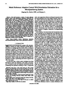
Schematic block diagram of the standard model reference adaptive control system used in our work. θ1 and θ2 are the gains from adaptive algorithm. . . . . . . . . . . . . . . . . . . . . . . . .
9
2.2
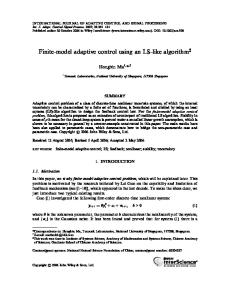
Schematic block diagram of the standard minimal control synthesis system used in our research. K and Kr are the gains from adaptive algorithm. . . . . . . . . . . . . . . . . . . . . . . . . . . . 12
3.1
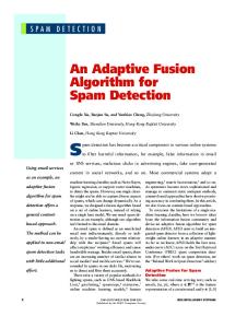
Representation of a subset of the system state space Σ defined by the system error signal and the system gains, for (a) the gain axes, K and Kr and (b) the transformed axes, Ks and Kd . The dashed line represents the set of equilibrium solutions, Γ: K + Kr = Ks = K E + KrE . . . . . . . . . . . . . . . . . . . . . . . . . 23
3.2
Example of sinusoid wave input (frequency 0.025 Hz) using the standard MRAC strategy. Parameters are γ = 4000, am = bm = 40, a = b = 20. ym oscillates about the value of 2. . . . . . . . . . . . . 28
3.3
Example of sinusoid wave input (frequency 0.025 Hz) using the standard MRAC strategy. Parameters are γ = 4000, am = bm = 40, a = b = 20. The figure shows the manifold described by equation 3.43. . . . . . . . . . . . . . . . . . . . . . . . . . . . . . . . . . . . . 29
3.4
Example of sinusoid wave input (frequency 0.025 Hz) using the standard MRAC strategy. Parameters are γ = 4000, am = bm = 40, a = b = 20. The figure shows the manifold in three dimensions way with axes of error signal e, and two system gains θ1 and θ2 . . 29
3.5
Example of sinusoid wave input (frequency 0.025 Hz) with ρ = 0 using the standard MRAC strategy. Parameters are γ = 4000, am = bm = 40, a = b = 20. ym oscillates about the value of 1. . . . . 30
Modified Model Reference Adaptive Control Algorithm to Improve System Robustness
L. Yang
LIST OF FIGURES
Page iv
3.6
Example of sinusoid wave input (frequency 0.025 Hz) using the standard MRAC strategy. Parameters are γ = 4000, am = bm = 40, a = b = 20. The figure shows the manifold described by equation 3.43. . . . . . . . . . . . . . . . . . . . . . . . . . . . . . . . . . . . . 31
3.7
Example of sinusoid wave input (frequency 0.025 Hz) using the standard MRAC strategy. Parameters are γ = 4000, am = bm = 40, a = b = 20. The figure shows the manifold in three dimensions way with axes of error signal e, and two system gains θ1 and θ2 . . 31
3.8
Example of sinusoid wave input (frequency 0.025 Hz) using the standard MRAC strategy. Parameters are γ = 4000, am = bm = 40, a = b = 20. ym oscillates about the value of 0. θ1 and θ2 trend to the Erzberger value 2 and 1 separately. . . . . . . . . . . . . . . . 32
3.9
Example of sinusoid wave input (frequency 0.025 Hz) using the standard MRAC strategy. Parameters are γ = 4000, am = bm = 40, a = b = 20. The figure shows the manifold described by equation 3.43. . . . . . . . . . . . . . . . . . . . . . . . . . . . . . . . . . . . . 33
3.10 Example of sinusoid wave input (frequency 0.025 Hz) using the standard MRAC strategy. Parameters are γ = 4000, am = bm = 40, a = b = 20. The figure shows the manifold in three dimensions way with axes of error signal e, and two system gains θ1 and θ2 . The star point shows the Erzberger value point. . . . . . . . . . . 33
3.11 Example of unity step input using the standard MRAC strategy. Parameters are γ = 80, am = bm = 40, a = b = 8, with the initial conditions θ1,0 = 5 and θ2,0 = 4. . . . . . . . . . . . . . . . . . . . . . 35
3.12 Example of unity step input using the standard MRAC strategy. Parameters are γ = 80, am = bm = 40, a = b = 8, with the initial conditions θ1,0 = 5 and θ2,0 = 4. The figure shows the manifold described by equation 3.46 without noise added in. . . . . . . . . 35
3.13 Example of unity step input with band-limited white noise using the standard MRAC strategy. The resulting both of the system gains θ1 and θ2 wind up to the presence of noise. . . . . . . . . . . 36
3.14 Example of unity step input with band-limited white noise using the standard MRAC strategy. The figure shows the manifolds described by equation 3.45 behavior in the presence of noise. . . 36
4.1
Schematic block diagram of the modified Minimal Control Synthesis system. Km and Krm are the modified gains from the new adaptive algorithm. . . . . . . . . . . . . . . . . . . . . . . . . . . . 40
4.2
Representation of the equilibrium positions and the λ1 eigenvalue and corresponding eigenvector ~e1 in the Σ state space, for (a) the standard MCS controller, and (b) the modified MCS controller. . 47
Modified Model Reference Adaptive Control Algorithm to Improve System Robustness
L. Yang
LIST OF FIGURES
Page v
4.3
Schematic block diagram of the modified Model Reference Adaptive Control system. θ1m and θ2m are the new gains from adaptive algorithm. . . . . . . . . . . . . . . . . . . . . . . . . . . . . . . . . . 53
4.4
Phase space geometry for using Lyapunov function approach. . . 58
5.1
Example of unity step input with ρ = 0, i.e. the standard MCS strategy. Parameters are α = 10, β = 1, am = bm = 40 and a = b = 8. The resulting steady-state values are Ks = 1 and Kd is unpredictable from the localized analysis. . . . . . . . . . . . . . . 63
5.2
Example of unity step input with ρ = 20. Parameters are α = 10, β = 1, am = bm = 40, a = b = 8, K ∗ = 0.9 and Kr∗ = 0.1. The resulting steady-state values are Ksm = K ∗ + Kr∗ = 1 and Kdm = K ∗ − Kr∗ =0.8. 64
5.3
Example of unity step input with band-limited white noise and ρ = 0, i.e. the standard MCS strategy. The resulting system gain Kd winds up due to the presence of noise, which means the control system is not robust with disturbance. . . . . . . . . . . . 65
5.4
Example of unity step input with band-limited white noise and ρ = 20. The resulting system gain Kdm is stable, indicating the control system is stable and robust. . . . . . . . . . . . . . . . . . 66
5.5
Example of sinusoid wave input (frequency 3 rad/sec, unity amplitude) with ρ = 0, i.e. the standard MRAC strategy, with initial values θ1,0 = 5 and θ2,0 = 4. Parameters are γ = 80, am = bm = 40 and a = b = 8. The resulting steady-state values are θ1 = 5 and θ2 = 4. . . . . . . . . . . . . . . . . . . . . . . . . . . . . . . . . . . . 68
5.6
Example of sinusoid wave input (frequency 3 rad/sec, unity amplitude) with ρ = 20, i.e. the modified MRAC strategy, with initial values θ1m,0 = 5 and θ2m,0 = 4. Parameters are γ = 80, am = bm = 40, a = b = 8, θ1∗ = 5 and θ2∗ = 4. The resulting steadystate values are θ1 = 5 and θ2 = 4. . . . . . . . . . . . . . . . . . . . 69
5.7
Example of sinusoid wave input (frequency 3 rad/sec, unity amplitude) with band-limited white noise and ρ = 0, i.e. the standard MRAC strategy (with initial values θ1,0 = 5 and θ2,0 = 4). The resulting both of the system gains θ1 and θ2 winds up due to the presence of noise, which means the control system is not robust with added noise. . . . . . . . . . . . . . . . . . . . . . . . 70
5.8
Example of sinusoid wave input (frequency 3 rad/sec, unity amplitude) with band-limited white noise and ρ = 20, i.e. the modified MRAC strategy (with initial values θ1m,0 = 5 and θ2m,0 = 4). The resulting both of the system gains are stable, indicating the control system is stable and robust. . . . . . . . . . . . . . . . . . 71
Modified Model Reference Adaptive Control Algorithm to Improve System Robustness
L. Yang
LIST OF TABLES
Page vi
List of Tables 2.1
Notations comparison between MCS and MRAC strategy . . . . 14
2.2
Parameters chosen for MCS and MRAC systems . . . . . . . . . . 16
Modified Model Reference Adaptive Control Algorithm to Improve System Robustness
L. Yang
Page vii
Page 1
Chapter 1 Introduction 1.1
Overview of model reference adaptive control and minimal control synthesis
“The survival or extinction of each organism is determined by that organism’s ability to adapt to its environment” is a famous conclusion in Charles Darwin’s book The Origin of Species. In the engineering field, people have the similar idea to make structures have the ability to adapt to their circumstances for better control results. For clear and direct purpose, here I quote the definition of adaptive controller of K.J. ˚ Astr¨om [1] – “An adaptive controller is a controller with adjustable parameters and a mechanism for adjusting the parameters.” A block diagram of an adaptive system is shown in Figure 1.1 Parameter adjustment Controller Parameters Input Controller
Control signal
Plant
Output
Figure 1.1: Block diagram of an adaptive system.
Adaptive control was extensively researched in purpose of designing autopilot Modified Model Reference Adaptive Control Algorithm to Improve System Robustness
L. Yang
1.1. OVERVIEW OF MODEL REFERENCE ADAPTIVE CONTROL AND MINIMAL CONTROL SYNTHESIS
Page 2
system for high performance aircraft in the 1950s [1]. There are many types of adaptive systems, and the model reference adaptive control (MRAC) system is an important class of adaptive controller, which we will study in this thesis. The minimal control synthesis (MCS) algorithm is a form of adaptive control based on MRAC [3], which we also study here. Researchers were beginning to be interested in the stability and robustness of adaptive control systems from the late 1970s, and they are still interested today [11, 12, 13, 14, 17, 18, 19, 20]. Many methods of designing and improving system stability and robustness have been researched, such as signal normalization [15], dead zone [16], and leakage [21]. The modified algorithm we develop in this thesis has similarities with the ‘leakage’ method, but is based on dynamical system analysis. More research about leakage can be found in [22, 23, 24, 25, 26]. In the following two sections we will introduce MRAC and MCS in more detail.
1.1.1
Model reference adaptive control
The model reference adaptive control (MRAC) was originally proposed to solve a problem in which the performance specifications are given in terms of a reference model. This model indicates how the process output ideally should respond to the command signal. A block diagram of the system is shown in Figure 1.2. The system has an ordinary feedback loop composed of the plant and controller and another feedback loop that changes the controller parameters. The parameters are changed on the basis of feedback from the error, which is the difference between the output of the plant and the output of the reference model. The mechanism for adjusting the parameters in a model reference adaptive system is usually obtained in one of the two ways: by using a gradient method [13] or by applying the stability theory [14]. Our work is concerned on the MRAC using Lyapunov stability theory. The theoretical formulation for Model reference adaptive control algorithm will be given in Chapter 2. The challenge with MRAC is that the adjustment mechanism, which brings the error to zero, must be designed so that the system is stable and robust.
Modified Model Reference Adaptive Control Algorithm to Improve System Robustness
L. Yang
1.2. DYNAMICAL SYSTEM APPROACH
Page 3
Model Controller parameters
Adjustment mechanism
Input Controller
Control signal
Plant
Output
Figure 1.2: Block diagram of a model reference adaptive system (MRAC).
1.1.2
MCS Adaptive Control
The Minimal Control Synthesis (MCS) algorithm is a form of adaptive control, developed from MRAC algorithm. MCS has been the subject of continuous research at the University of Bristol since 1989. The first experimental evidence and formulation of MCS is in [3, 4]. Several versions of the algorithm have appeared, such as the decentralized [5], the extended [6], and error driven version [8]. Comparing to MRAC, MCS algorithm does not require any knowledge of plant dynamics [7]. The details and theoretical formulation for the Minimal Control Synthesis algorithm will be given in Chapter 2.
1.2
Dynamical system approach
In this section we introduce an approach to analyse the local stability of a nonlinear dynamical system. The approach is the one we use to analyse the system stability of the standard and modified MRAC and MCS system in our later work. This dynamical system approach can be presented by four steps in order: 1. Set up a dynamical system. 2. Find out the system equilibrium points. 3. Extend the dynamical system as Taylor series and evaluate the Jacobian matrix at the equilibrium points. 4. Analyse system stability by Jacobian matrix eigenvalues and eigenvectors. Modified Model Reference Adaptive Control Algorithm to Improve System Robustness
L. Yang
1.3. LYAPUNOV STABILITY THEORY AND GLOBAL STABILITY APPROACH
Page 4
Here we give a simple example by using the first order MRAC system, to show how to use this dynamical approach to analyse the local stability. To set up a dynamical system we need to choose the state vector. In this example we choose the error signal e, the feed forward adaptive gain θ1 and the feedback adaptive gain θ2 as the state vector. So we have the state vector ξ = {e, θ1 , θ2 }. Then we can set up a first order dynamical system of the form ξ˙ = f (ξ, t) by giving the first order differential equations of each state vector. After setting up the dynamical system, we need to find out the system equiˆ t) = 0, where ξˆ librium points. To do this we need to resolve the function f (ξ, represents the equilibrium points. Then we linearize the dynamical system by using Taylor series based on the equilibrium point as ˆ + Dfξ (ξ)(ξ ˆ − ξ) ˆ ξ˙ ≈ f (ξ)
(1.1)
ˆ is Jacobian matrix, should be evaluated at each equilibrium point where Dfξ (ξ) ˆ After we have the Jacobian matrix, we need to work out the eigenvalues and ξ = ξ. eigenvectors for the Jacobian matrix. We then analyse the local system stability close to the equilibrium point based on the Lyapunov stability theory. The Lyapunov stability theory will be introduced in next section. More details about the dynamical system approach can be found in [27, 29, 30, 32, 35, 36, 37, 38].
1.3
Lyapunov stability theory and global stability approach
At the end of nineteenth century, the Russian mathematician Lyapunov gave the abstract definition and a theory of stability for a dynamical system, and this is a fundamental contribution to the stability theory for nonlinear systems. In this section we introduce the Lyapunov lemma we used in our research. Since the dynamical system we setup is a nonlinear system. After linearized the system and evaluated the Jacobian matrix at the equilibrium point, we use The Indirect Method of Lyapunov [29] to analyse local stability of the nonlinear system. This lemma is that if the real part of the Jacobian matrix eigenvalues evaluated at an equilibrium point are negative, the nonlinear system is asymptotically stable close to this equilibrium point. Modified Model Reference Adaptive Control Algorithm to Improve System Robustness
L. Yang
1.4. OBJECTIVES OF WORK
Page 5
To prove the modified MRAC algorithm is globally asymptotically stable, we use The Direct Method of Lyapunov [31, 1, 27] as: The origin is a globally asymptotically stable equilibrium point for the system x˙ = f (x), if a Lyapunov function V (x) can be found that 1. V (x) > 0 for all x 6= 0 and V (0) = 0, 2. V˙ (x) < 0 for all x 6= 0, and 3. V → ∞, when ||x|| → ∞. The global stability approach we followed can be found in an example in the design of MRAS using Lyapunov theory [1].
1.4
Objectives of work
The main objective of this thesis is to eliminate the gain ‘wind up’ phenomenon in model reference adaptive control system. This is motivated by the work of Wagg and Neild [9]. In their work, they found that the gains for the adaptive controller have the ‘wind up’ behaviour due to noise in MCS systems, which harms the system robustness in practical application. Questions are what exactly causes the system gains ‘wind up’, and how we can eliminate this phenomenon to improve the system robustness. In this thesis we extend the work of [9], and start from analysing the Minimal Control Synthesis system in a simple case of unity step input. We use the dynamical system approach to analyse the local stability of this simple case, and we found theoretically that the gain ‘wind up’ phenomenon has the relationship with the zero eigenvalue of the Jacobian matrix. Our idea was to examine whether we could create an adaptive control algorithm without the zero eigenvalue. We then tested many different possibilities to remove the zero eigenvalues of the Jacobian matrix and derived a modified algorithm. Theoretical proof and simulation results show the gain ‘wind up’ is eliminated by this modified structure. After this, the modified algorithm is tested in MCS system with a general input case. Up to this point we are interested in whether this modified algorithm can be Modified Model Reference Adaptive Control Algorithm to Improve System Robustness
L. Yang
1.5. THESIS OVERVIEW
Page 6
applied in the MRAC system. Following this idea, we analyse the local stability of the standard MRAC, and find that the MRAC system (based on the Lyapunov rule, [1]) has the same problem of gain ‘wind up’ in presence of noise. By using the same idea, we modified the MRAC structure by removing the zero eigenvalue of the Jacobian matrix. It is proved theoretically and by simulation results that the modified MRAC algorithm eliminates the gain ‘wind up’, and system demonstrates robust behaviour due to noise. Because all of our work above is based on the local stability analysis close to the system equilibrium point, naturally it leads to a problem whether the system has stable behaviour far away from the equilibrium point in presence of noise. Here we give a theoretical proof that the system is globally asymptotically stable based on The Direct Method of Lyapunov.
1.5
Thesis overview
In chapter 1 we gave the background knowledge of subject we study in this thesis. We gave an overview of Model Reference Adaptive Control (MRAC) and Minimal Control Synthesis (MCS). We introduced the method we use to analyse the local stability in this thesis, the dynamical system approach, and the Lyapunov theory. In chapter 2, we give theoretical formulations of MRAC based on Lyapunov rule and MCS algorithm. We then show the method of choosing parameters of the MRAC and MCS system to set up the numerical models. After that, we introduce the geometry of phase space used in our work. Chapters from chapter 3 are organized by following the sequence of our real research work, from MCS to MRAC. We analyse MCS system by starting from a special case of unity step input, and then extend to the case of general input signal. For the MRAC system, we analyse it directly from the general input case, and later extend research to a global case. In chapter 3 we analyse the standard MRAC and MCS systems by using error dynamical approach. In section 3.1 and 3.2 we setup the dynamical system for MCS, and then analyse the local stability close to the equilibrium points in a simple case of unity step input. In section 3.3 and 3.4 we apply the dynamical system approach to the MRAC system, setting up the dynamical system in section 3.3 and presenting
Modified Model Reference Adaptive Control Algorithm to Improve System Robustness
L. Yang
1.5. THESIS OVERVIEW
Page 7
the local stability analysis in a general input case in section 3.4. Later in section 3.5 we give an explanation to the gain ‘wind-up’ phenomenon in the standard MRAC system by analysing the simulation results. In chapter 4 we discuss a modified algorithm, which has been designed to eliminate the system zero eigenvalue. The work in the first three sections is focused on the MCS system. In section 4.1 we set up a dynamical system for the modified MCS algorithm with a simple case, i.e. unity step input signal, and analyse its local stability close to the equilibrium point in section 4.2. In section 4.3 we give theoretical proof of the modified MCS algorithm with general input signals. In the later part of this chapter our work is focused on the modified MRAC algorithm with general input signals. We set up a dynamical system for the modified MRAC strategy in section 4.4, and present local stability analysis in section 4.5. In section 4.6 we give the theoretical proof that the modified MRAC algorithm is globally asymptotically stable. In chapter 5 we test the modified algorithms for MCS and MRAC, which are developed and proved theoretically in previous chapters, by computer simulation method with the software MATLABr . We set up the numerical models, and use computer simulation to show the graphic results of both standard and modified control algorithm. In section 5.1 we compare the result of the modified MCS algorithm to the standard MCS. In section 5.2 we compare the result of the modified MRAC strategy to the standard MRAC. Finally, conclusions are drawn in chapter 6.
Modified Model Reference Adaptive Control Algorithm to Improve System Robustness
L. Yang
Page 8
Chapter 2 Theoretical formulation for Model reference adaptive control algorithm In this chapter we will give detail descriptions in theoretical formulations of MRAC based on Lyapunov rule in section 2.1 and MCS algorithm in section 2.2. In section 2.3 we show the method of choosing parameters of the MRAC and MCS system to set up the numerical models. In section 2.4 we introduce the geometry of phase space used in our work. Compared to the modified versions in later chapters we call the MRAC and MCS versions in this chapter the ‘standard’ versions.
2.1
Theoretical formulation for MRAC based on Lyapunov rule
Since the MIT rule appeared as an original MRAC approach, research has shown that there is no guarantee that an adaptive controller based on the MIT rule will give a stable closed-loop system [1]. Therefore there is a desire to find other methods to design adaptive controllers to achieve the stability system behaviour. One important step was to use Lyapunov’s stability theory to construct stable algorithms for adjusting parameters in adaptive system. Our work is also based on the standard MRAC system using Lyapunov stability theory. Here we will give the theoretical formulations of the standard MRAC, using the notation adopted by [1].
Modified Model Reference Adaptive Control Algorithm to Improve System Robustness
L. Yang
2.1. THEORETICAL FORMULATION FOR MRAC BASED ON LYAPUNOV RULE
Page 9
We consider a first order MRAC control problem with plant dynamics modeled by y(t) ˙ = −ay(t) + bu(t),
(2.1)
where y is the plant state, a and b are constants and u is the control signal. In general we consider a controller which uses both the state variables and the reference signal, uc (t), factored respectively by the control gains, such that u(t) = θ1 (t)uc (t) − θ2 (t)y(t),
(2.2)
where, θ1 (t) is the feed forward adaptive gain and θ2 (t) the feedback adaptive gain [1]. Substituting for u in equation 2.1 gives y˙ = −(a + bθ2 )y + bθ1 uc .
(2.3)
The plant is now controlled to follow the output from a reference model with known dynamics y˙ m (t) = −am ym (t) + bm uc (t),
(2.4)
where ym is the state of the reference model, am and bm are linear reference equivalents of a and b [2, 7]. Reference Model . ym= -amym+bmuc uc
θ1
+-
u=θ1uc- θ2y
ym e
+
. Plant y= -ay+bu
y
θ2 Adaptive Algorithm
Figure 2.1: Schematic block diagram of the standard model reference adaptive control system used in our work. θ1 and θ2 are the gains from adaptive algorithm.
Figure 2.1 shows a block diagram representation of the standard model reference adaptive control system used in our work. The objective of the control algorithm is Modified Model Reference Adaptive Control Algorithm to Improve System Robustness
L. Yang
2.2. THEORETICAL FORMULATION FOR MCS
Page 10
for e → 0 as t → ∞, where e = y − ym is the error signal, and we can reformulate the dynamics of the system in terms of the error as e˙ = −am e − (bθ2 + a − am )y + (bθ1 − bm )uc .
(2.5)
Comparing equations 2.3 and 2.4, we can see that for exact matching between the plant and the reference model, the following relations hold a + bθ2E = am ,
(2.6)
bθ1E = bm ,
where ( )E denotes a constant Erzberger gains [30]. From equation 2.6 we can obtain expressions for the Erzberger gain values as θ2E =
am − a , b
(2.7)
bm . b
(2.8)
θ1E =
We can use equations 2.7 and 2.8 to express equation 2.5 as e˙ = −am e − b(θ2 − θ2E )(ym + e) + b(θ1 − θ1E )uc .
(2.9)
This equation here is the error dynamic system described by Erzberger gains. The model reference adaptive control system we discussed here is based on Lyapunov rule θ˙ = γϕe, where θ = [θ1 , θ2 ]. γ is a positive constant and ϕ = {−uc , y}T . The Lyapunov rule can be described by equations
2.2
θ˙1 = −γuc e,
(2.10)
θ˙2 = γye.
(2.11)
Theoretical formulation for MCS
In this section we give the theoretical formulation of the standard MCS algorithm used in our work, adopting the standard MCS notation [3]. We begin by considering a linear control problem in general state space formulation x(t) ˙ = Ax(t) + Bu(t), Modified Model Reference Adaptive Control Algorithm to Improve System Robustness
(2.12) L. Yang
2.2. THEORETICAL FORMULATION FOR MCS
Page 11
where x is the n × 1 state variable vector, u is the m × 1 control signal vector, A is a n × n matrix representing the linear dynamics of the plant, and B is a n × m matrix. In general we consider a controller which uses both the state variables and the reference signal, factored respectively by the gains K(t) and Kr (t), such that u(t) = K(t)x(t)+Kr (t)r(t), where r(t) is the reference (demand) signal, K(t) is the feedback adaptive gain and Kr (t) the feed forward adaptive gain [12, 1, 30]. Substituting for u in equation 2.12 gives x˙ = Ax + B(Kx + Kr r) = (A + BK)x + BKr r.
(2.13)
The plant is now controlled to follow the output from a reference model with known dynamics x˙ m (t) = Am xm (t) + Bm r(t),
(2.14)
where xm is the state of the reference model and Am and Bm are linear reference equivalents of A and B [2, 7]. This approach requires that the dimensions of equation 2.14 are the same as equation 2.12, such that dim{xm } = dim{x}, dim{r} = dim{u}, dim{Am } = dim{A} and dim{Bm } = dim{B}. Figure 2.2 shows a block diagram of the standard minimal control synthesis (MCS) system used in our research. The objective of the control algorithm is for xe → 0 as t → ∞, where xe = xm −x is the error signal between the reference model output and the plant output. We can reformulate the dynamics of the system in terms of the error as x˙ e = Am xe + (Am − A − BK)x + (Bm − BKr )r.
(2.15)
Comparing equations 2.13 and 2.14, we can see that for exact matching between the plant and the reference model, the following relations hold A + BK E = Am , BKrE = Bm .
(2.16)
Assuming all matrix (pseudo) inverses exist we can obtain expressions for the Modified Model Reference Adaptive Control Algorithm to Improve System Robustness
L. Yang
2.2. THEORETICAL FORMULATION FOR MCS
Page 12
Reference Model . xm=Amxm+Bmr r
Kr
++
xm Xe
+ -
u=Kx+Krr
Plant . x=Ax+Bu
Ce
ye
x
K Adaptive Algorithm
Figure 2.2: Schematic block diagram of the standard minimal control synthesis system used in our research. K and Kr are the gains from adaptive algorithm.
gain values as K E = B † (Am − A), KrE = B † Bm ,
(2.17)
where ( )† denotes the pseudo-inverse. However, a generic objective of model reference adaptive control is to operate without explicit knowledge of the plant parameter values A and B. As a result we do not wish to solve equation 2.17, but by substituting Am , Bm in equation 2.15 with Erzberger gains, we have x˙ e = Am xe + B(K E − K)x + B(KrE − Kr )r.
(2.18)
Then equation 2.18 can be expressed as x˙ e = Am xe + BΦT w,
(2.19)
where Φ = (k E − k), k E = {K E , KrE }T , k = {K, Kr }T and w(t) = {x, r}T and we assume that B has a pseudo-inverse such that BB † = I. In this formulation Φ can be thought of as a gain or parameter error: i.e. the difference between the Erzberger gains (equation 2.17) and the current adaptive gain values. Note also that this formulation implicitly assumes that Erzberger gains exist for the system. In general we wish to design an adaptive controller for as wide a class of systems {A, B} as possible whilst maintaining the overall stability of the system. For general Modified Model Reference Adaptive Control Algorithm to Improve System Robustness
L. Yang
2.2. THEORETICAL FORMULATION FOR MCS
Page 13
model reference adaptive control, the adaptive gains are commonly defined in a proportional plus integral formulation Z t k=α ye w(τ )dτ + βye w(t),
(2.20)
0
where α and β are control weightings representing the adaptive effort, and ye = Ce xe where Ce can be chosen to ensure the stability of the feed forward block [2]. Equation 2.20 can be obtained by using hyperstability (i.e. the Popov Criteria) see [1, 28, 11] for detailed derivations.
Equation 2.20 gives an expression which computes the adaptive gain values, k(t), from time t = 0 to an arbitrary time t. However, α and β need to be selected in advance, and clearly have a significant influence on the rate of adaption as they act as fixed gain values which multiply the proportional and integral parts of the controller gain. In contrast to most MRAC control strategies, in the MCS strategy the initial gains are set to zero rather than to the Erzberger gains.
It is worth emphasizing that equation 2.20 relies on no a prior knowledge of the plant matrices A and B. Examples of adaptive gain laws which require knowledge of B directly or A in the Kalman–Yakubovich Lemma can be found in the literature (examples are discussed in [1]) but do not apply in this case. This restriction presents a problem in estimating an appropriate Ce matrix. From the Kalman–Yakubovich Lemma, this matrix can be found explicitly only with knowledge of both A and B. A pragmatic solution is to estimate Ce based on the required settling time of the plant, ts — see [7]. This is the solution we adopt here, such that for a scalar first order system Ce = 4/ts .
Because MCS algorithm was developed from the MRAC strategy, we can find out many connections between these two systems. Table 2.1 shows the connections between the MCS and MRAC algorithm. The items of ‘gains differential’ and ‘gains for modified algorithm’ will be described in chapters 3 and 4.
Modified Model Reference Adaptive Control Algorithm to Improve System Robustness
L. Yang
2.2. THEORETICAL FORMULATION FOR MCS
Plant Reference Model
Control Signal
Gains
MCS
MRAC
x˙ = −ax + bu
y˙ = −ay + bu
x˙ m = −am xm + bm r
y˙ m = −am ym +bm uc
xm ↔ ym r ↔ uc
u = Kx + Kr r
u = −θ2 y + θ1 uc
K ↔ −θ2 K r ↔ θ1
KE =
a−am b
KrE = Error signal Gains differential (chapter 3)
Gains for modified algorithm (chapter 4)
Page 14
bm b
θ2E =
Comparable notations x↔y
am −a b
K E ↔ −θ2E
bm b
KrE ↔ θ1E
θ1E =
xe = xm − x
e = y − ym
xe ↔ −e
K˙ = αCe xe x + βCe [...]
θ˙2 = γye
α↔γ
K˙ r = αCe xe r + βCe [...] Km = ρ2 s ∗ K + s+ρ 2K s+ρ2
θ˙1 = −γuc e
β↔0
θ2m = ρ2 s ∗ θ + s+ρ 2 θ2 s+ρ2 2
Km ↔ −θ2m
Krm = ρ2 ∗ + s+ρ 2 Kr
θ1m = ρ2 s ∗ θ + s+ρ 2 θ1 s+ρ2 1
Krm ↔ θ1m
s K s+ρ2 r
K ∗ ↔ −θ2∗
Kr∗ ↔ θ1∗
Table 2.1: Notations comparison between MCS and MRAC strategy
Modified Model Reference Adaptive Control Algorithm to Improve System Robustness
L. Yang
2.3. PARAMETERS CHOSEN FOR MRAC AND MCS SYSTEM
2.3
Page 15
Parameters chosen for MRAC and MCS system
In this section we show how to choose the parameters of the MRAC and MCS system to set up the numerical models for our research work. We use a first order MCS system as an example to show the method of choosing parameters from the system state-space functions. A table will be given for all the parameters used in the MRAC and MCS models. For a first order MCS system, the state-space function of the plant can be derived from equation 2.12 in section 2.2 in this chapter as x˙ = −ax + bu,
(2.21)
where x is the plant state, a and b are constants and u is the control signal for the first order MCS system. The plant for experiment can be set up by following the system transfer function x b = , (2.22) u s+a where s is the Laplace transfer factor. For the first order system we choose the parameter as [7] a=
4 , tsp
(2.23)
and 4λ , (2.24) tsp is the settling time of the plant, and λ is the D.C. gain for the system. b=
where tsp
Since a and b can be tested from the experiment, the plant settling time tsp can be calculated from equation 2.23 as 4 tsp = , a and the D.C. gain λ can be calculated from equations 2.23 and 2.24 as b λ= . a
(2.25)
(2.26)
In the numerical model, we estimate the plant settling time tsp , and calculate the parameters a and b by equations 2.23 and 2.24. The state space function of reference model for the first order MCS system can be derived from equation 2.14 in section 2.2 in this chapter as x˙ m = −am xm + bm r, Modified Model Reference Adaptive Control Algorithm to Improve System Robustness
(2.27) L. Yang
2.4. GEOMETRY OF PHASE SPACE
Page 16
MRAC For the plant For the reference Model For the adaptive algorithm
a=
4 , tsp
am =
4 , ts
b=
MCS 4λ tsp
bm =
4 ts
γ chosen arbitrarily
a=
4 , tsp
am =
4 , ts
b=
4λ tsp
bm =
4 ts
α, β chosen arbitrarily, holding the relationship: α = 10β. Ce = 4/ts .
Table 2.2: Parameters chosen for MCS and MRAC systems where xm is the output of the reference model, am and bm are linear reference equivalents of a and b, and r is the reference signal for the first order system. The reference model can be set up by following the transfer function as xm bm = . r s + am
(2.28)
am and bm can be chosen for the first order system as [7] am =
4 , ts
(2.29)
and 4 , (2.30) ts where ts is the settling time of the reference model. Usually, the settling time of the bm =
reference model is less than the the settling time of the plant, and can be chosen arbitrarily. To set up the reference model for numerical model or experiment, we can calculate am and bm from equations 2.29 and 2.30. The parameters in the MRAC system are chosen in the similar way as MCS system. Other parameters such as α, β in the MCS algorithm and γ in the MRAC algorithm are chosen arbitrarily based on experience. All the parameters used in MRAC and MCS algorithm will be listed in the table 2.2.
2.4
Geometry of phase space
In this section we introduce the geometry of phase space we used in the thesis. The phase space we formed here is based on state vectors of the dynamical system, which Modified Model Reference Adaptive Control Algorithm to Improve System Robustness
L. Yang
2.4. GEOMETRY OF PHASE SPACE
Page 17
we set up to analyse the system stability. Basically for analysing the system stability of the MRAC and MCS system, we are interested in the error signal and two system gains from adaptive algorithm. But in several sections, we need to use different coordinates for clearer and more convenient analysis, and the phase space geometry changes as well. We will give the details of each phase space we used in this thesis. When we analyse the system stability of the standard MCS in section 3.1 we use the error signal xe and two adaptive gains K and Kr to form the phase space. But for presenting a simpler and clearer analysis, we change the coordinate to Ks and Kd in section 3.1.1. Ks = K + Kr and Kd = K − Kr . The changing of phase space geometry can be seen from figure 3.1. In section 4.1 and 4.2 we present local stability analysis for the modified MCS algorithm. We keep using the error signal xe , but two gains become Ksm and Kdm , the modified version. In section 4.3 as we analyse the general input case, we use xe , Km and Krm as phase space for convenience. When we analyse the system stability of the standard MRAC from section 3.3 to 3.5, we use the error signal e and two adaptive gains θ1 and θ2 to form the phase space. In the modified MRAC sections 4.4 and 4.5, the phase space is formed by e, θ1m , and θ2m . When we prove modified MRAC system is globally stable in section 4.6, we choose the state vector by using e, θ1m − θ1E and θ2m − θ2E . Because we need the system equilibrium point at origin of phase space. Further details will be discussed in corresponding sections.
Modified Model Reference Adaptive Control Algorithm to Improve System Robustness
L. Yang
Page 18
Chapter 3 Using error dynamical approach to analyse standard model reference adaptive control algorithm In this chapter we will analyse the standard MRAC and MCS systems by using error dynamical approach. To apply this approach, first we need to derive the error dynamical system. In section 3.1 and 3.2 we setup the dynamical system for MCS, and then analyse the local stability close to the equilibrium points in a simple case of unity step input. In section 3.3 and 3.4 we apply the dynamical system approach to the MRAC system, setting up the dynamical system in section 3.3 and presenting the local stability analysis in a general case in section 3.4. In section 3.5 we give an explanation to the gain ‘wind-up’ phenomenon in the standard MRAC system.
3.1
Set up dynamical system for MCS
In this section we consider reformulating the error system (equation 2.18) developed in section 2.2 as a nonlinear dynamical system. The model reference adaptive system can be written as a dynamical system of the form ν˙ = f (ζ, t), where ν = {xe , K, Kr }T is the state vector. For a first order system, we define Am = −am , A = −a, Bm = bm , B = b. So from equation 2.15 we can write x˙ e = −am xe + (a − am − bK)x + (bm − bKr )r,
Modified Model Reference Adaptive Control Algorithm to Improve System Robustness
(3.1)
L. Yang
3.1. SET UP DYNAMICAL SYSTEM FOR MCS
Page 19
and the Erzberger gains for this first order system can be written as KE =
a − am , b
(3.2)
bm . (3.3) b in equation 3.1 using the Erzberger gain equations and subKrE =
We substitute am , bm
stitute x by xm − xe , giving x˙ e = −am xe + b(K E − K)(xm − xe ) + b(KrE − Kr )r.
(3.4)
The gains K, Kr were defined by equation 2.20 in section 2.1 and for first order systems can be simplified to K(t) = α
t
Z
Ce xe xdτ + βCe xe x,
(3.5)
0
Kr (t) = α
Z
t
Ce xe rdτ + βCe xe r.
(3.6)
0
˙ K˙ r can be expressed as Substituting x by xm − xe , the differential of the gains K, K˙ = αCe xe (xm − xe ) + βCe [x˙ e (xm − 2xe ) + xe x˙ m ],
(3.7)
K˙ r = αCe xe r + βCe (x˙ e r + xe r). ˙
(3.8)
We then substitute x˙ e in equation 3.7 and 3.8 by equation 3.4, to give K˙ = αCe xe (xm − xe ) + βCe xe x˙ m + βCe (xm − 2xe )[−am xe
(3.9)
+b(K E − K)(xm − xe ) + b(KrE − Kr )r],
K˙ r = αCe xe r +βCe xe r˙ +βCe r[−am xe +b(K E −K)(xm −xe )+b(KrE −Kr )r]. (3.10) Equations 3.4, 3.9 and 3.10 define a closed-loop dynamical system in the form ν˙ = f (ν, t) =
E
E
rKrE
−am xe − b(K − K)xe + b(xm K − xm K + − rKr ) αCe xe (xm − xe ) + βCe xe x˙ m + βCe (xm − 2xe )[−am xe +b(K E − K)(xm − xe ) + b(KrE − Kr )r] αCe xe r + βCe xe r˙ + βCe r[−am xe + b(K E − K)(xm − xe ) + b(KrE − Kr )r]
.
(3.11)
Modified Model Reference Adaptive Control Algorithm to Improve System Robustness
L. Yang
3.1. SET UP DYNAMICAL SYSTEM FOR MCS
where
Page 20
xe
. ν= K Kr
(3.12)
In the analysis presented in this study, we consider a simple case of a unity step input: x˙ e K˙ K˙ r
r = xm = 1. So the dynamical system ν˙ = f (ν, t) becomes −am xe − b(K E − K)xe + b(K E − K + KrE − Kr ) E = . αCe xe (1 − xe ) + βCe (1 − 2xe )[−am xe − b(K − K)xe E E +b(K − K + K − K )] r r E E E αCe xe + βCe [−am xe − b(K − K)xe + b(K − K + Kr − Kr )] (3.13)
To perform a localized analysis on a dynamical system, we need to find out the equilibrium points. Therefore we need to find νˆ such that f (ˆ ν , t) = 0, where νˆ is the equilibrium point and in general ( ˆ ) denotes equilibrium values. By inspection ˆ Kˆr )T exist, of equation 3.13 we can see that a set of equilibrium points νˆ = (0, K, with the condition that ˆ +K ˆ r = K E + KrE , K such that in general an equilibrium point can be expressed as xˆe 0 E E ˆ ˆ νˆ = K = K + K − K r . r ˆr ˆr K K
(3.14)
(3.15)
We can see that the limitation condition described by equation 3.14 defines a manifold of the set of equilibrium points. Because K E +KrE is constant, this manifold becomes a line, and position of equilibrium points can vary along the line. Here we ˆ +K ˆ r = K E + KrE with xe = 0 call this infinite gain manifold, Γ. Γ is the line of K in the system phase space, shown in figure 3.1a.
Modified Model Reference Adaptive Control Algorithm to Improve System Robustness
L. Yang
3.1. SET UP DYNAMICAL SYSTEM FOR MCS
3.1.1
Page 21
A coordinate change for gain variable in the system state space
To make the system simpler and clearer for analysis, we introduce Ks and Kd to transform the system axes, Ks = K + K r , Kd = K − Kr .
(3.16)
where in general the subscript ()s denotes the sum of the system gains and the subscript ()d denotes the difference between the system gains. In the later part of this section, we will show using this transformation the last row and column of Jacobian matrix contains just zero terms. This transformation makes our stability analysis much easier than working in the original coordinates. From equation 3.16 we have K = 21 (Ks + Kd ), Kr = 12 (Ks − Kd ).
(3.17)
We substitute K, Kr in the equation 3.13 by equation 3.17, and have 1 x˙ e = −am xe − b[K E − (Ks + Kd )]xe + b(K E + KrE − Ks ), 2
(3.18)
1 K˙ = αCe xe (1−xe )+βCe (1−2xe ){−am xe −b[K E − (Ks +Kd )]xe +b(K E +KrE −Ks )}, 2 (3.19) 1 K˙ r = αCe xe + βCe {−am xe − b[K E − (Ks + Kd )]xe + b(K E + KrE − Ks )}. (3.20) 2 From equation 3.16, 3.19 and 3.20, we can have K˙ s and K˙ d as K˙ s = K˙ + K˙ r = 2αCe xe − αCe xe 2 + 2βCe (1 − xe ){−am xe − b[K E − 21 (Ks + Kd )]xe +b(K E + KrE − Ks )}, (3.21) 1 ˙ K˙ r = −αCe xe 2 −2βCe xe {−am xe −b[K E − (Ks +Kd )]xe +b(K E +KrE −Ks )}. K˙ d = K− 2 (3.22) Using the systems dynamics, equation 3.13, the system can be rewritten in the new coordinates if we redefine our state vector as ξ = {xe , Ks , Kd }. The closed-loop
Modified Model Reference Adaptive Control Algorithm to Improve System Robustness
L. Yang
3.2. LOCAL STABILITY ANALYSIS OF MCS ALGORITHM
control dynamics ξ˙ = f (ξ, t) can be expressed as x˙ −am xe − b[K E − 12 (Ks + Kd )]xe + b(K E + KrE − Ks ) e 2αCe xe − αCe xe 2 + 2βCe (1 − xe ){−am xe K˙ s = −b[K E − 21 (Ks + Kd )]xe + b(K E + KrE − Ks )} −αCe xe 2 − 2βCe xe {−am xe − b[K E − 12 (Ks + Kd )]xe +b(K E + K E − Ks )} K˙ d r
Page 22
.
(3.23)
ˆ t) = 0. By To find out the equilibrium points, we need to solve the equation f (ξ, inspection of equation 3.23 it can be seen that the solution is 0 xˆe E E ˆ ˆ ξ= Ks = K + Kr . ˆ ˆ Kd Kd
(3.24)
ˆ d value, From equation 3.24 we can see that the equilibrium point can have any K and must be located on the infinite gain manifold Γ. This manifold is shown in the transformed coordinate system in Figure 3.1b.
3.2
Local stability analysis of MCS algorithm
In this section we use the dynamical system approach to analyse the system stability close to the equilibrium points. To analyse the local stability of the system near the equilibrium points, we expand the right hand side of the equation 3.23 at ξˆ as a Taylor series, giving ˆ + Dfξ (ξ)(ξ ˆ − ξ) ˆ + O[(ξ − ξ) ˆ 2 ], ξ˙ = f (ξ)
(3.25)
ˆ is Jacobian Matrix evaluated at an equilibrium point ξ = ξ. ˆ Using where Dfξ (ξ) equation 3.23, which defines an equilibrium position, and the system dynamics, we
Modified Model Reference Adaptive Control Algorithm to Improve System Robustness
L. Yang
3.2. LOCAL STABILITY ANALYSIS OF MCS ALGORITHM
Page 23
E
Kr
E
Γ : Ks = K + Kr
Kd
K
Ks
xe
xe Γ: K + Kr = KE + KrE
(a)
(b)
Figure 3.1: Representation of a subset of the system state space Σ defined by the system error signal and the system gains, for (a) the gain axes, K and Kr and (b) the transformed axes, Ks and Kd . The dashed line represents the set of equilibrium solutions, Γ: K + Kr = Ks = K E + KrE .
obtain −am − − − Kd ) −b 0 ˆ = 2αC + 2βC [−a − 1 b(K E − K E − K )] −2βC b 0 . Dfξ (ξ) d e e e m r 2 0 0 0
1 b(K E 2
KrE
(3.26)
To work out Jacobian eigenvalues , we need to solve |D − λI| = 0, where D is ˆ I the identity matrix with the same dimension the Jacobian matrix evaluated at ξ, as Jacobian matrix, and λ the eigenvalues. Here we have |D − λI| = λ{[am + 12 b(K E − KrE − Kd ) + λ](2βCb + λ) +b{2αC + 2βC[−am − 12 b(K E − KrE − Kd )]}} = 0
(3.27)
From solving the equation 3.27, we have λ = 0 and 1 λ2 + λ[am + 2βCb + b(K E − KrE − Kd )] + 2αbC = 0. 2
(3.28)
After solving the equation 3.28, we have the three eigenvalues for the Jacobian Modified Model Reference Adaptive Control Algorithm to Improve System Robustness
L. Yang
3.3. SET UP DYNAMICAL SYSTEM FOR MRAC
Page 24
matrix as λ1 = 0 and λ2,3 are given by λ2,3 = − 21 [am + 2βCe b + 12 b(K E − KrE − Kd )] ± 21 S, where S 2 = [am + 2βCe b + 12 b(K E − KrE − Kd )]2 − 8αbCe .
(3.29)
The λ1 = 0 eigenvalue has a corresponding eigenvector ~e = [0, 0, 1]T , i.e. in the direction of Γ the line of equilibrium solutions. Previous studies show that system gains will wind up with noise, if the adaptive system has a zero eigenvalue [9, 10], which means the adaptive system will become unstable due to noise. In chapter 5, we will show simulation results of gains winding up with noise present in standard MCS system.
3.3
Set up dynamical system for MRAC
In this section we setup the dynamical system based on the error signal equation 2.9 developed in section 2.1 of chapter 2. We consider the model reference adaptive system as a dynamical system of the form ξ˙ = f (ξ, t), where ξ = {e, θ1 , θ2 }T is the state vector [1, 9, 10, 2, 12]. The steady state dynamics after a unity step input, i.e. when uc = ym = 1, has been studied first as a simple case, the method is similar as our work in sections 3.1 and 3.2. In the following two sections 3.3 and 3.4 we mainly concerned about the case of general input signal, rather than unity step input. The dynamical system equation 2.9 becomes e˙ = −am e − b(θ2 − θ2E )e + b(θ1 − θ1E )uc − b(θ2 − θ2E )ym .
(3.30)
Equation 2.10 and 2.11 become θ˙1 = −γuc e.
(3.31)
θ˙2 = γe2 + γym e.
(3.32)
Modified Model Reference Adaptive Control Algorithm to Improve System Robustness
L. Yang
3.4. USING DYNAMICAL SYSTEM APPROACH TO ANALYSE THE LOCAL STABILITY OF STANDARD MRAC NEAR A SINGLE EQUILIBRIUM POINT
So the dynamical system can be written as −am e − b(θ2 − θ2E )e + b(θ1 − θ1E )uc − b(θ2 − θ2E )ym e˙ θ˙1 = −γuc e ˙θ2 γe2 + γym e
3.4
Page 25
.
(3.33)
Using dynamical system approach to analyse the local stability of standard MRAC near a single equilibrium point
In this section we use the dynamical system approach to analyse the local stability, where the system can have any kind of input signals. The local analysis will be applied close to a single equilibrium point first. The more general analysis will be described in section 3.5. To perform a localized analysis on a dynamical system, we first need to find ˆ t) = 0, where ξˆ is the out the equilibrium points. Therefore we need to find f (ξ, equilibrium point and in general (ˆ) denotes equilibrium values. By inspection of equation 3.33 we have e = 0 and (θˆ1 − θ1E )uc − (θˆ2 − θ2E )ym = 0.
(3.34)
Equation 3.34 defines a manifold of the set of equilibrium points ξˆ = {0, θˆ1 , θˆ2 }T . Here we discuss the case of θˆ1 = θ1E and θˆ2 = θ2E . Since uc and ym are time varying equation 3.34 can be satisfied, and a signal equilibrium point can be expressed as eˆ 0 E ˆ ξ = θˆ1 = θ1 (3.35) . θˆ2 θ2E We can see from equation 3.35, the equilibrium manifold becomes a single point. Based on this single equilibrium point, we apply the dynamical system local stability analysis. Modified Model Reference Adaptive Control Algorithm to Improve System Robustness
L. Yang
3.4. USING DYNAMICAL SYSTEM APPROACH TO ANALYSE THE LOCAL STABILITY OF STANDARD MRAC NEAR A SINGLE EQUILIBRIUM POINT
Page 26
To analyse the local stability of the system near the equilibrium points, we expand the right hand side of the equation 3.33 at ξˆ as a Taylor series, from which the linear approximation to the system is ˆ − ξ), ˆ ξ˙ ≈ Dfξ (ξ)(ξ
(3.36)
ˆ is the Jacobian Matrix evaluated at an equilibrium point ξ = ξ. ˆ Using where Dfξ (ξ) equation 3.33, which defines an equilibrium position, and the system dynamics, we obtain
−am
ˆ Dfξ (ξ) = −γuc γym
buc −bym 0
0
0
0
.
(3.37)
The three eigenvalues for the Jacobian matrix are λ1 = 0 and λ2,3 = − 21 am ±
1 2
p
2 + u2 ). a2m − 4bγ(ym c
(3.38)
The corresponding eigenvectors are e1 = [0,
ym T , 1] uc
γuc γym T , ] λ2 λ2 γuc γym T , ] e3 = [1, − λ3 λ3 e2 = [1, −
(3.39) (3.40) (3.41)
Check equation 3.38 we can see in the case of am > 0, 2 if a2m − 4bγ(ym + u2c ) = 0, λ2,3 = − 12 am < 0. 2 If a2m − 4bγ(ym + u2c ) < 0, the eigenvalues are complex, and the real part
Re{λ2 } = Re{λ3 } = − 12 am < 0. 2 2 If a2m − 4bγ(ym + u2c ) > 0, in the case of b and γ are positive, 4bγ(ym + u2c ) > 0. p 2 + u2 ), so Then we can have am > a2m − 4bγ(ym c p 1 1 2 2 2 λ2,3 = − 2 am ± 2 am − 4bγ(ym + uc ) are always less than zero.
So for the eigenvalues λ2,3 , system always gives asymptotically stable behaviour along the eigenvectors directions for λ2,3 . Modified Model Reference Adaptive Control Algorithm to Improve System Robustness
L. Yang
3.5. AN EXPLANATION TO THE SYSTEM GAINS ’WIND-UP’ PHENOMENON
Page 27
The λ1 = 0 eigenvalue has a corresponding eigenvector ~e = [0, yumc , 1]T . Previous studies showed if the adaptive system has a zero eigenvalue the presence of noise or other disturbances can cause gain drift or ‘wind up’ [9, 10]. In chapter 5, we will show how this gain wind up with noise present in the standard MRAC system manifests itself in computer simulation.
3.5
An explanation to the system gains ’wind-up’ phenomenon
This section is an extension of the research in section 3.4. We will show the existence of the equilibrium manifold in the general input signal case. Based on the manifold we give a series results by computer simulation, which give an explanation to the gain ‘wind-up’ phenomenon. The equation 3.34 defines a manifold of a set of equilibrium points ξˆ = {0, θˆ1 , θˆ2 }T . To perform a complete analysis, let us first consider the case where ym /uc = C, where C is a constant. In this case the manifold equation 3.34 can be rewritten as θˆ1 − θˆ2 = θ1E − Cθ2E .
(3.42)
We can see that the right hand side of the equation 3.42 is constant. So equation 3.42 denotes a straight line of equilibrium solutions in {e, θ1 , θ2 } space. In the general case, when uc and hence ym are time varying (with the relationship between ym and uc being governed by equation 2.4) equation 3.34 can be satisfied if θˆ1 = θE and θˆ2 = θE , giving an equilibrium point at ξˆ = {0, θE , θE }T , as we already 1
2
1
2
discussed in section 3.4. Other positions along the manifold given by equation 3.34 require time varying θˆ1 and θˆ2 for time varying uc and ym . However, by checking the second and third equation in the equation set 3.33, we can see that for θˆ1 and θˆ2 to vary with time the error e must be non-zero. Therefore at other positions along the manifold, the system can not settle on the manifold for time varying uc , but will oscillate in a limit cycle around the manifold. In this case where the error is not exactly zero, strictly this system behaviour forms a different manifold, described by −am e − b(θˆ2 − θ2E )e + b(θˆ1 − θ1E )uc − b(θˆ2 − θ2E )ym = 0. Modified Model Reference Adaptive Control Algorithm to Improve System Robustness
(3.43) L. Yang
3.5. AN EXPLANATION TO THE SYSTEM GAINS ’WIND-UP’ PHENOMENON
Page 28
To demonstrate the manifold formed by the limit cycle oscillations, we use a sinusoid wave as the reference signal uc with frequency 0.025Hz and unity amplitude, oscillating about the value of 2. The plant and reference model parameters are taken to be a = b = 20 and am = bm = 40 (ts = 0.1, tsp = 0.2 are settled, i.e. steady state). From equations 2.7 and 2.8 the Erzberger gains θ1E and θ2E are θ1E = 2 and θ2E = 1. Numerical examples are shown for the standard MRAC strategy without noise added in. Figure 3.2 shows the output from the reference model ym , the error signal e, and the two gains θ1 and θ2 . Figure 3.3 shows the manifold described by equation 3.43. Figure 3.4 shows the manifold in three dimensions with axes of error signal e, and two system gains θ1 and θ2 . By inspection of figure 3.2, we can see that the system gains θ1 and θ2 oscillate around a stable value close to the Erzberger gains (θ1E = 2 and θ2E = 1) and the error oscillates about zero. These oscillations form a limit cycle, showed in two dimensions in figure 3.3, and in {e, θ1 , θ2 } space in figure 3.4.
ym
3 2
e
1 4 2 0 −2
θ1
2.0339
40
60
80
100
120
140
160
180
200
20
40
60
80
100
120
140
160
180
200
20
40
60
80
100
120
140
160
180
200
20
40
60
80
100 Time
120
140
160
180
200
2.0338 2.0337 1.0339
θ2
−9
x 10 20
1.0338 1.0337
Figure 3.2: Example of sinusoid wave input (frequency 0.025 Hz) using the standard MRAC strategy. Parameters are γ = 4000, am = bm = 40, a = b = 20. ym oscillates about the value of 2.
This example is rather artificial as the reference model output ym is always greater than one. The reason this example was chosen is that it ensures persistence Modified Model Reference Adaptive Control Algorithm to Improve System Robustness
L. Yang
3.5. AN EXPLANATION TO THE SYSTEM GAINS ’WIND-UP’ PHENOMENON
Page 29
−9
Manifold: L.H.S. of Eq.3.43
2
x 10
1.5 1 0.5 0 −0.5 −1 −1.5 −2
20
40
60
80
100 Time
120
140
160
180
200
Figure 3.3: Example of sinusoid wave input (frequency 0.025 Hz) using the standard MRAC strategy. Parameters are γ = 4000, am = bm = 40, a = b = 20. The figure shows the manifold described by equation 3.43.
−9
x 10 3
e
2 1 0 −1 1.0339 1.0339
2.0339 1.0338
2.0339 1.0338
θ
2.0338 1.0337
2.0337
2
θ1
Figure 3.4: Example of sinusoid wave input (frequency 0.025 Hz) using the standard MRAC strategy. Parameters are γ = 4000, am = bm = 40, a = b = 20. The figure shows the manifold in three dimensions way with axes of error signal e, and two system gains θ1 and θ2 . Modified Model Reference Adaptive Control Algorithm to Improve System Robustness
L. Yang
3.5. AN EXPLANATION TO THE SYSTEM GAINS ’WIND-UP’ PHENOMENON
Page 30
of excitation [29]. We now consider an example, using the same parameters as the previous example, where ym equals zero once a cycle (oscillating about the value of 1). Figure 3.5 shows ym , the error e, and the two gains θ1 and θ2 .
ym
2 1 0
e
10
−6
x 10 20
40
60
80
100
120
140
160
180
200
20
40
60
80
100
120
140
160
180
200
20
40
60
80
100
120
140
160
180
200
20
40
60
80
100 Time
120
140
160
180
200
5 0
θ1
−5 2.0145 2.014 2.0135
θ2
1.0145 1.014 1.0135
Figure 3.5: Example of sinusoid wave input (frequency 0.025 Hz) with ρ = 0 using the standard MRAC strategy. Parameters are γ = 4000, am = bm = 40, a = b = 20. ym oscillates about the value of 1.
It can be seen that the error is very small except in the region of the oscillation where ym is close to zero. In this region since ym , and hence uc , is small the rate of gain for a given magnitude of error is reduced, resulting in insufficient adaption to keep the error small. The consequence of this on the manifold equation 3.43 is shown in figure 3.6. It can be seen that there is a breakdown in the relationship once per oscillation when the manifold equation does not equal zero. During these regions the system gains cease to oscillate on a limit cycle, but move to new values close to Erzberger gains. However, over the rest of the region the system does oscillate on a limit cycle. This system behaviour forms a manifold, resulting in a series of limit cycles over multiple oscillations as shown in figure 3.7. Here we give one more example to strengthen our analysis of the existence of the ’manifold’. We still use the same parameters as the previous examples, but ym Modified Model Reference Adaptive Control Algorithm to Improve System Robustness
L. Yang
3.5. AN EXPLANATION TO THE SYSTEM GAINS ’WIND-UP’ PHENOMENON
Page 31
−5
Manifold:L.H.S. of Eq.3.43
4
x 10
3 2 1 0 −1 −2 −3 −4
20
40
60
80
100 Time
120
140
160
180
200
Figure 3.6: Example of sinusoid wave input (frequency 0.025 Hz) using the standard MRAC strategy. Parameters are γ = 4000, am = bm = 40, a = b = 20. The figure shows the manifold described by equation 3.43.
−6
x 10 8 6
e
4 2 2.0144
0
2.0142 −2 1.0142 1.0141
2.014 1.014 1.0139 1.0138 1.0137 1.0136 θ2
2.0138 2.0136
θ
1
Figure 3.7: Example of sinusoid wave input (frequency 0.025 Hz) using the standard MRAC strategy. Parameters are γ = 4000, am = bm = 40, a = b = 20. The figure shows the manifold in three dimensions way with axes of error signal e, and two system gains θ1 and θ2 . Modified Model Reference Adaptive Control Algorithm to Improve System Robustness
L. Yang
3.5. AN EXPLANATION TO THE SYSTEM GAINS ’WIND-UP’ PHENOMENON
Page 32
equals zero twice a cycle (oscillating about the value of 0) to demonstrate a more general case. Figure 3.8 shows ym , the error e, and the two gains θ1 and θ2 .
ym
1 0
e
−1 1800 1820 2 x 10⁻³
1840
1860
1880
1900
1920
1940
1960
1980
2000
1820
1840
1860
1880
1900
1920
1940
1960
1980
2000
1820
1840
1860
1880
1900
1920
1940
1960
1980
2000
1820
1840
1860
1880
1900 Time
1920
1940
1960
1980
2000
0
θ1
−2 1800 1.75 1.7
θ2
1800 0.75 0.7 1800
Figure 3.8: Example of sinusoid wave input (frequency 0.025 Hz) using the standard MRAC strategy. Parameters are γ = 4000, am = bm = 40, a = b = 20. ym oscillates about the value of 0. θ1 and θ2 trend to the Erzberger value 2 and 1 separately.
Figure 3.8 shows clearly that during the regions where ym is close to zero, errors become bigger, and the system gains do not oscillate on a limit cycle anymore, but move to a new values close to Erzberger gains. This system behaviour forms the manifold described by equation 3.43 is shown in figure 3.9. It can be seen that there is a breakdown in the relationship twice per oscillation when the manifold equation does not equal to zero. This results in the manifold with a series of limit cycles over multiple oscillations as shown in figure 3.10. To summarize the above analysis, we have two conclusions. Firstly, for the general input case only in the case of a single equilibrium point, ξˆ = {0, θE , θE }T we 1
2
discussed in section 3.4, can the error signal e equal to zero. Secondly, in the nonzero error condition the manifold is described by equation 3.43. During the segments where reference model output ym is close to zero, system gains stop oscillating on a limit cycle, but move to new values closer to the Erzberger gains.
Modified Model Reference Adaptive Control Algorithm to Improve System Robustness
L. Yang
3.5. AN EXPLANATION TO THE SYSTEM GAINS ’WIND-UP’ PHENOMENON
Page 33
Manifold: L.H.S. of Eq.3.43
0.01 0.008 0.006 0.004 0.002 0 −0.002 −0.004 −0.006 −0.008 −0.01 1800
1820
1840
1860
1880
1900 Time
1920
1940
1960
1980
2000
Figure 3.9: Example of sinusoid wave input (frequency 0.025 Hz) using the standard MRAC strategy. Parameters are γ = 4000, am = bm = 40, a = b = 20. The figure shows the manifold described by equation 3.43.
−3
x 10 4
e
2 0
2
−2 −4 1
0.8
1.5 θ1 0.6 θ
2
0.4
0.2
0
1
Figure 3.10: Example of sinusoid wave input (frequency 0.025 Hz) using the standard MRAC strategy. Parameters are γ = 4000, am = bm = 40, a = b = 20. The figure shows the manifold in three dimensions way with axes of error signal e, and two system gains θ1 and θ2 . The star point shows the Erzberger value point. Modified Model Reference Adaptive Control Algorithm to Improve System Robustness
L. Yang
3.5. AN EXPLANATION TO THE SYSTEM GAINS ’WIND-UP’ PHENOMENON
Page 34
All the above numerical models are shown for the standard MRAC strategy without noise added in. To show the gain ‘wind up’ phenomenon we add noise into system. In the following numerical example, we demonstrate a case by using a simple case when the reference demand uc (t) in a unity step input. The step function is defined as t < t0
uc = 0,
u˙ c = 0
t > t0
uc = 1,
u˙ c = 0
,
(3.44)
and uc = ym = 1. The manifold equation 3.43 is simplified to am θˆ1 − θˆ2 = (θ1E − θ2E ) + e + (θˆ2 − θ2E )e. b
(3.45)
For the case of e = 0, this manifold will be further simplified to θˆ1 − θˆ2 = θ1E − θ2E = 1,
(3.46)
which represents the line manifold. Figure 3.11 shows the output from the reference model ym , the error signal e, and the two gains θ1 and θ2 with no noise system. Figure 3.13 shows the same items but with band-limited white noise added into the system. Figure 3.12 shows the manifold (described by equation 3.45) without noise. Figure 3.14 shows the manifold (described by equation 3.45) behavior with band-limited white noise added into the system. By inspection of the figure 3.13, we can see that both system gains θ1 and θ2 wind up due to the presence of noise. However from figure 3.14 we can see the manifold described by equation 3.45 (error is non zero) gives a stable behaviour. A possible reason to explain these two figures is that the system gains ‘wind up’ along this manifold. Based on the analysis in this section we have given an explanation of the gain ‘wind up’ phenomenon. In the general condition, because of non-zero error conditions a manifold exists in {e, θˆ1 , θˆ2 } space, and the single equilibrium point, ξˆ = {0, θ1E , θ2E }T is a special point on this manifold, where the error signal e is equal to zero. System gains have freedom to move along the manifold. During the segments where reference model output ym is close to zero, system gains stop oscillating on a Modified Model Reference Adaptive Control Algorithm to Improve System Robustness
L. Yang
3.5. AN EXPLANATION TO THE SYSTEM GAINS ’WIND-UP’ PHENOMENON
Page 35
ym
1.5 1 0.5 0 0 0.1
10
20
30
40
50
60
70
80
0
10
20
30
40
50
60
70
80
0
10
20
30
40
50
60
70
80
0
10
20
30
40 Time
50
60
70
80
e
0
θ1
−0.1
5
θ2
4.9
4 3.9
Figure 3.11: Example of unity step input using the standard MRAC strategy. Parameters are γ = 80, am = bm = 40, a = b = 8, with the initial conditions θ1,0 = 5 and θ2,0 = 4. 1.1 1.08 1.06
Manifold: θ1 − θ2
1.04 1.02 1 0.98 0.96 0.94 0.92 0.9
0
10
20
30
40 Time
50
60
70
80
Figure 3.12: Example of unity step input using the standard MRAC strategy. Parameters are γ = 80, am = bm = 40, a = b = 8, with the initial conditions θ1,0 = 5 and θ2,0 = 4. The figure shows the manifold described by equation 3.46 without noise added in. Modified Model Reference Adaptive Control Algorithm to Improve System Robustness
L. Yang
3.5. AN EXPLANATION TO THE SYSTEM GAINS ’WIND-UP’ PHENOMENON
Page 36
ym
1.5 1 0.5 0 0 0.5
10
20
30
40
50
60
70
80
0
10
20
30
40
50
60
70
80
0
10
20
30
40
50
60
70
80
0
10
20
30
40 Time
50
60
70
80
e
0 −0.5
θ1
100 50 0
θ2
100 50 0
Figure 3.13: Example of unity step input with band-limited white noise using the standard MRAC strategy. The resulting both of the system gains θ1 and θ2 wind up to the presence of noise.
Manifold: L.H.S. of Eq.3.45
5 4 3 2 1 0 −1 −2 −3
0
10
20
30
40 Time
50
60
70
80
Figure 3.14: Example of unity step input with band-limited white noise using the standard MRAC strategy. The figure shows the manifolds described by equation 3.45 behavior in the presence of noise. Modified Model Reference Adaptive Control Algorithm to Improve System Robustness
L. Yang
3.5. AN EXPLANATION TO THE SYSTEM GAINS ’WIND-UP’ PHENOMENON
Page 37
limit cycle, but move to new values closer to the Erzberger gains in the case where there is no noise. And in the rest of the segments the system oscillates on a limit cycle. But because of this freedom, with noise added into the system, gains travel along the manifold, causing the phenomenon of gain ‘wind up’.
Modified Model Reference Adaptive Control Algorithm to Improve System Robustness
L. Yang
Page 38
Chapter 4 A modified algorithm to remove the system zero eigenvalue In this chapter we will discuss a modified algorithm, which has been designed to eliminate the system zero eigenvalue. We derived this modified algorithm by testing many different possibilities to remove the zero eigenvalues of Jacobian matrix. In this thesis, for convenience we present only the final modified result directly, and analyse its local stability by using dynamical system approach close to the equilibrium point, and compare it with the standard algorithm. The work in the first three sections is focused on the MCS system. In section 4.1 we set up a dynamical system for the modified MCS algorithm with a simple case, i.e. unity step input signal, and analyse its local stability close to the equilibrium point in section 4.2. In section 4.3 we give theoretical proof of the modified MCS algorithm with general input signals. From section 4.4 to 4.6 our work is focused on the modified MRAC algorithm with general input signals. We set up a dynamical system for the modified MRAC strategy in section 4.4, and present local stability analysis in section 4.5. In section 4.6 we give theoretical proof that the modified MRAC algorithm is globally asymptotically stable.
Modified Model Reference Adaptive Control Algorithm to Improve System Robustness
L. Yang
4.1. SET UP DYNAMICAL SYSTEM FOR THE MCS MODIFIED ALGORITHM
4.1
Page 39
Set up dynamical system for the MCS modified algorithm
In this section we set up a dynamical system for the modified MCS algorithm by considering a simple case, i.e. unity step input signal. Our idea is that we test the modified algorithm first in the unity step input case, and prove that the gain ‘wind up’ phenomenon is removed by eliminating the zero eigenvalues. Theoretically the reason is that we improve the system stability from neutral stability (of the standard algorithm) to asymptotical stability (of the modified algorithm). Then we test the modified algorithm in the general input signal case in the later section. We start by considering the modification to eliminate the undesirable zero eigenvalue in the standard MCS. The new control signal can be written as u = Km x + Krm r,
(4.1)
where Km and Krm are the new adaptive gains. In general, the subscript ()m denotes parameters relating to the new modified system. The gains can be expressed in terms of the standard gains K and Kr as Km =
s ρ2 K + K ∗, s + ρ2 s + ρ2
(4.2)
Krm =
s ρ2 K + Kr∗ , r 2 2 s+ρ s+ρ
(4.3)
where ρ is a real number, s the Laplace transform factor and K ∗ , Kr∗ are constant gain values. A condition on the gains K ∗ and Kr∗ is derived in the subsequent analysis. This modified MCS algorithm is shown in figure 4.1. To derive the error dynamics we need to compute x˙ e . From equation 2.18, for a first order system we have x˙ e = −am xe + b(K E − Km )(xm − xe ) + b(KrE − Krm )r.
(4.4)
To simplify the analysis, as with the standard MCS analysis, we introduce Ksm and Kdm to transform the axes of the dynamical system Ksm = Km + Krm , Kdm = Km − Krm . Modified Model Reference Adaptive Control Algorithm to Improve System Robustness
(4.5)
L. Yang
4.1. SET UP DYNAMICAL SYSTEM FOR THE MCS MODIFIED ALGORITHM
Reference Model . xm=Amxm+Bmr r
Krm
++
u=Kmx+Krmr
Page 40
xm Xe
+ Plant . x=Ax+Bu
Ce
ye
x
Km Modified Adaptive Algorithm
Figure 4.1: Schematic block diagram of the modified Minimal Control Synthesis system. Km and Krm are the modified gains from the new adaptive algorithm.
From equation 4.5 we have Km = 21 (Ksm + Kdm ),
(4.6)
Krm = 12 (Ksm − Kdm ).
By substituting Km , Krm in equation 4.4, for the unity input condition of r = xm = 1 the error dynamics can be expressed as 1 x˙ e = −am xe − b[K E − (Ksm + Kdm )]xe + b(K E + KrE − Ksm ). 2
(4.7)
From equations 4.2 and 4.3, we have K˙ m = K˙ + ρ2 K ∗ − ρ2 Km ,
(4.8)
K˙ rm = K˙ r + ρ2 Kr∗ − ρ2 Krm .
(4.9)
To find equations for K˙ sm , K˙ dm using equations 4.5, 4.8 and 4.9 we can write K˙ sm = K˙ s − ρ2 Ksm + ρ2 K ∗ + ρ2 Kr∗ ,
(4.10)
K˙ dm = K˙ d − ρ2 Kdm + ρ2 K ∗ − ρ2 Kr∗ ,
(4.11)
By eliminating K˙ s , K˙ d and x˙ e using equation 3.23 these equations become K˙ sm = 2αCe xe − αCe xe 2 + 2βCe (1 − xe ){−am xe − b[K E − 12 (Ksm + Kdm )]xe +b(K E + KrE − Ksm )} − ρ2 [Ksm − (K ∗ + Kr∗ )], (4.12) Modified Model Reference Adaptive Control Algorithm to Improve System Robustness
L. Yang
4.2. MCS LOCAL STABILITY ANALYSIS USING THE DYNAMICAL SYSTEM APPROACH
¤ £ K˙ dm = −αCe xe 2 − 2βCe xe {−am xe − b K E − 21 (Ksm + Kdm ) xe +b(K E + KrE − Ksm )} − ρ2 [Kdm − (K ∗ − Kr∗ )].
Page 41
(4.13)
Now we have the modified first order model reference adaptive control algorithm as a dynamical system of the form ξ˙m = f (ξm , t), using the modified state vector ξm = {xe , Ksm , Kdm } giving x˙ e −am xe − b[K E − 1/2(Ksm + Kdm )]xe + b(K E + KrE − Ksm ) 2 2 ∗ ∗ 2αCe xe − αCe xe − ρ [Ksm − (K + Kr )] + 2βCe (1 − xe ){−am xe ˙ E E E Ksm = . −b[K − 1/2(Ksm + Kdm )]xe + b(K + Kr − Ksm )} 2 2 ∗ ∗ −αCe xe − ρ [Kdm − (K − Kr )] − 2βCe xe {−am xe E E E K˙ dm −b[K − 1/2(Ksm + Kdm )]xe + b(K + Kr − Ksm )} (4.14) In this dynamical system the parameters am , b, α, β and Ce are constant. For the system ξ˙m = f (ξm , t), where ξm = {xe , Ksm , Kdm } we can define a (subset of the complete) phase (or state) space Σ = {R × R × R : xe , Ksm , Kdm }. Km , Krm are the real control gains of the adaptive system. Ksm , Kdm can be considered as the result after switching axes to simplify the phase space for the purpose of better analyzing the stability of the dynamical system.
4.2
MCS local stability analysis using the dynamical system approach
In this section we use a dynamical system approach to analyse the local stability of the modified MCS algorithm in the case of a unity step input, close to the equilibrium points. To use dynamical system approach, we first need to find the equilibrium points of the system. Therefore we need to solve the equation f (ξˆm , t) = 0. Setting
Modified Model Reference Adaptive Control Algorithm to Improve System Robustness
L. Yang
4.2. MCS LOCAL STABILITY ANALYSIS USING THE DYNAMICAL SYSTEM APPROACH
xe = 0, equation 4.14 becomes x˙ e b(K E + KrE − Ksm ) K˙ sm = −ρ2 [Ksm − (K ∗ + K ∗ )] + 2βCe b(K E + K E − Ksm ) r r K˙ dm −ρ2 [Kdm − (K ∗ − Kr∗ )]
Page 42
= 0.
(4.15)
It can be seen from equation 4.15 that the following conditions for an equilibrium point can be derived ˆ sm = K E + KrE , K ˆ sm = K ∗ + Kr∗ , K
(4.16)
ˆ dm = K ∗ − Kr∗ . K ˆ sm = K ˆm + K ˆ rm and K ˆ dm = K ˆm − K ˆ rm , by using the last two Also because K equations in equation set 4.16 we can have ˆm + K ˆ rm = K ∗ + Kr∗ , K ˆm − K ˆ rm = K ∗ − Kr∗ . K
(4.17)
Furthermore, by adding and subtracting the two equations in equation set 4.17, we have ˆm = K∗ K
(4.18)
ˆ rm = Kr∗ . K
(4.19)
From equations 4.18 and 4.19 we can see in the modified MCS algorithm, we have these additional conditions to force the modified system gains to move toward the fixed values K ∗ and Kr∗ . The limitation of choosing K ∗ and Kr∗ will be explained later in this section. By using the first two equations in equation set 4.16 we can have the condition for equilibrium to occur K ∗ + Kr∗ = K E + KrE ,
(4.20)
where using equations 3.2 and 3.3, K E + KrE = (a − am + bm )/b. Provided that we select a reference model with unity steady-state gain, am = bm , this reduces to K E + KrE = a/b, i.e. the inverse of the steady-state gain of the plant, which can Modified Model Reference Adaptive Control Algorithm to Improve System Robustness
L. Yang
4.2. MCS LOCAL STABILITY ANALYSIS USING THE DYNAMICAL SYSTEM APPROACH
Page 43
usually be obtained by a simple testing procedure. In practice, to ensure no steadystate error the reference model steady-state gain would normally be set to unity. The modified algorithm needs a priori information of the steady-state gain of the plant. In contrast to this, standard MCS requires no a priori knowledge about the plant since the initial gains are taken to be zero, and normally MRAC strategies require knowledge of both the steady-state gain and the settling time of the plant such that the initial gains can be set to an estimate of the Erzberger gains. The solution to f (ξˆm , t) = 0 is a single (equilibrium) point given by 0 xˆe ˆ sm = K E + K E . ξˆm = K r ∗ ∗ ˆ K − Kr Kdm
(4.21)
We can tell from equation 4.21 that, substituting the values of K ∗ and Kr∗ , the equilibrium point becomes a single fixed point, instead of a infinite gain manifold. This equilibrium point is dependent on the value of K ∗ and Kr∗ that are selected. To present the dynamical system approach of the local stability analysis, we expand the right hand side of equation 4.14 at the equilibrium point ξˆm , as a Taylor series, giving ξ˙m = f (ξˆm ) + Dfξm (ξˆm )(ξm − ξˆm ) + O[(ξm − ξˆm )2 ],
(4.22)
where Dfξm (ξˆm ) is the Jacobian matrix evaluated at ξˆm . Using equation 4.14, the Jacobian matrix Dfξm (ξˆm ) can be evaluated at the equilibrium point ξm = ξˆm to analyse the localized stability of the modified system dynamics
−am − 2b (K E − KrE − K ∗ + Kr∗ )
−b
0
b E E ∗ ∗ 2 . Dfξm (ξˆm ) = 2αC + 2βC [−a − (K − K − K + K )] −2βC b − ρ 0 e e m e r r 2 2 0 0 −ρ (4.23) Modified Model Reference Adaptive Control Algorithm to Improve System Robustness
L. Yang
4.2. MCS LOCAL STABILITY ANALYSIS USING THE DYNAMICAL SYSTEM APPROACH
Page 44
To work out the Jacobian eigenvalues , we need to solve |D − λI| = 0, where D is the Jacobian matrix evaluated at ξˆm , I the identity matrix with the same dimension as Jacobian matrix, and λ eigenvalues. Here we have (D − λI) = b E E ∗ ∗ −am − 2 (K − Kr − K + Kr ) − λ −b 0 2αCe + 2βCe [−am − b (K E − K E − K ∗ + K ∗ )] −2βCe b − ρ2 − λ . 0 r r 2 2 0 0 −ρ − λ (4.24) By transforming equation 4.24 we can have (D − λI) = b E E ∗ ∗ −b 0 −am − 2 (K − Kr − K + Kr ) − λ 2 −(λ + ρ ) 2αCe + 2βCe [−am − 2b (K E − KrE − K ∗ + Kr∗ )] −2βCe b − ρ2 − λ 0 . 0 0 1 (4.25) Letting equation 4.25 equal to zero, we can see that this Jacobian has three eigenvalues, λ1 = −ρ2 and b 1 1 λ2,3 = − [am + 2βCe b + ρ2 + (K E − KrE − K ∗ + Kr∗ )] ± S, 2 2 2
(4.26)
where S 2 = [am + 2βCe b + ρ2 + 2b (K E − KrE − K ∗ + Kr∗ )]2
(4.27)
−4[am ρ2 + 2αbCe + 2b ρ2 (K E − KrE − K ∗ + Kr∗ )].
We also need to work out eigenvectors corresponding to each eigenvalues. For doing this we need to solve (D − λI)~e = 0, where ~e are the corresponding vectors. Here we have −b 0 −am − 2b (K E − KrE − K ∗ + Kr∗ ) − λ 2αCe + 2βCe [−am − b (K E − K E r 2 −K ∗ + Kr∗ )] −2βCe b − ρ2 − λ 0 0 0 −ρ2 − λ
e 1 e2 = 0. e3 (4.28)
Modified Model Reference Adaptive Control Algorithm to Improve System Robustness
L. Yang
4.2. MCS LOCAL STABILITY ANALYSIS USING THE DYNAMICAL SYSTEM APPROACH
Page 45
From equation 4.28 we have b [−am − (K E − KrE − K ∗ + Kr∗ ) − λ]e1 − be2 = 0, 2
(4.29)
(ρ2 + 2βCe b + λ)e2 = e1 , 2αCe + 2βC[−am − 2b (K E − KrE − K ∗ + Kr∗ )]
(4.30)
−(ρ2 + λ)e3 = 0.
(4.31)
Substituting e1 in equation 4.29 by equation 4.30, we have e2 {λ2 + λ[am + 2βCe b + ρ2 + 2b (K E − KrE − K ∗ + Kr∗ )] + [am ρ2 + 2αbc + 2b ρ2 (K E − KrE − K ∗ + Kr∗ )]}/{2αCe + 2βCe [−am
(4.32)
− 2b (K E − KrE − K ∗ + Kr∗ )} = 0. In the case of λ = −ρ2 , we have e3 = e3 (from equation 4.31), e2 = 0 (from equation 4.32), and e1 = 0 (from equation 4.30). So the eigenvector is ~e1 = [0, 0, 1]T . In the case of λ = λ2,3 , we get e2 = e2 (from equation 4.32), e3 = 0 (from equation 4.31), and e1 = the last two eigenvectors
e2 (ρ2 +2βCe b+λ) (from equation 4.30). 2αCe +2βCe [−am − 2b (K E −KrE −K ∗ +Kr∗ )] 2 ρ +2βCe b+λ2,3 T are ~e2,3 = [ 2αC +2βC [−a b E E ∗ ∗ , 1, 0] . e e m − 2 (K −Kr −K +Kr )]
So
Here we have all three corresponding eigenvectors as ~e1 = [0, 0, 1]T ,
(4.33)
~e2 = [
ρ2 + 2βCe b + λ2 , 1, 0]T , b ∗ ∗ E E 2αCe + 2βCe [−am − 2 (K − Kr − K + Kr )]
(4.34)
~e3 = [
ρ2 + 2βCe b + λ3 , 1, 0]T . b ∗ ∗ E E 2αCe + 2βCe [−am − 2 (K − Kr − K + Kr )]
(4.35)
Here we discuss the system local stability close to the equilibrium point ξˆm based on Lyapunov Stability Theory. First we analyse the stability along the eigenvector directions of ~e2 and ~e3 . To make our discussing clear and convenient, we let b A = [am + 2βCe b + ρ2 + (K E − KrE − K ∗ + Kr∗ )], 2
(4.36)
b B = [am ρ2 + 2αbCe + ρ2 (K E − KrE − K ∗ + Kr∗ )]. 2
(4.37)
and
From equation 4.26 and 4.27 we can see that if A2 = 4B, then S = 0 and λ2,3 = − 12 A. Modified Model Reference Adaptive Control Algorithm to Improve System Robustness
L. Yang
4.2. MCS LOCAL STABILITY ANALYSIS USING THE DYNAMICAL SYSTEM APPROACH
Page 46
(The values of am , bm , a, b, α, β, andCe are chosen for the reference model and plant for numerical model in computer simulation. They are available from testing the real plant in experiments. Details of choosing the values for numerical model will be described in Chapter 5.) Provided A > 0, which means 2 K ∗ − Kr∗ < (K E − KrE ) + (am + 2βCe b + ρ2 ), b
(4.38)
the system will be asymptotically stable in the directions of ~e2 and ~e3 . If A2 < 4B, then the eigenvalues λ2,3 are complex, and Re{λ2 } = Re{λ3 } = − 12 A. Provided A > 0 the system will be asymptotically stable in direction of ~e2 and ~e3 . If A2 > 4B and B > 0, which means K ∗ − Kr∗ < (K E − KrE ) +
2 (am ρ2 + 2αbCe ). bρ2
(4.39)
We can have |A| > |S|. At the same time condition 4.38 must be satisfied, therefore the eigenvalues λ2,3 will be negative. The system will be asymptotically stable in direction of ~e2 and ~e3 . Comparing the conditions 4.38 and 4.39, we need 2 2 (K E − KrE ) + (am + 2βCe b + ρ2 ) < (K E − KrE ) + 2 (am ρ2 + 2αbCe ). b bρ
(4.40)
From condition 4.40 we can derive the limitation of ρ2 value. From the above analysis we can see that in the case of unity step input, if ρ value is chosen properly, the Jacobian eigenvalues λ2 and λ3 have negative values. Based on Lyapunov stability theory, the system is asymptotically stable along the direction of ~e2 and ~e3 . To give a brief summary of our analysis to the modified algorithm: ρ2 in equation 4.2 and 4.3 is actually the absolute value of the Jacobian eigenvalues λ1 at equilibrium point. Using the standard MCS strategy (corresponding to ρ = 0), we have shown that there is an eigenvalue λ1 = 0 which acts in the eigenvector direction ~e1 = [0, 0, 1]T , i.e. in the direction of the line of equilibrium points Γ [9]. This neutral stability in the direction of the set of equilibrium positions can lead to gain wind-up with the presence of noise, as will be shown in the computer simulations in chapter 5. Modified Model Reference Adaptive Control Algorithm to Improve System Robustness
L. Yang
4.3. THEORETICAL PROOF OF SYSTEM STABILITY IN GENERAL INPUT SIGNAL CASE
Page 47
With the modified system the zero eigenvalue is replaced with the eigenvalue λ1 = −ρ2 . Provided ρ is real and non-zero, this results in a locally stable system. The corresponding eigenvector is, as with the MCS strategy, in the direction ~e1 = [0, 0, 1]T . The modified system contains a single equilibrium point at xe = 0, K = K ∗ and Kr = Kr∗ . Therefore in contrast to the MCS strategy, the modified strategy is asymptotically stable in the ~e1 = [0, 0, 1]T direction, thereby eliminating the possibility of gain wind-up. These features are summarized graphically in figure 4.2. Numerical examples of both the modified and the unmodified algorithms will be given in Chapter 5.
Kd
equilibrium manifold Γ
Kdm
^ K dm E
K +
Ks
xe
equilibrium point x
KrE xe
e1, λ1 = - ρ2
e1, λ1 = 0
(a)
Ksm
^ K sm
(b)
Figure 4.2: Representation of the equilibrium positions and the λ1 eigenvalue and corresponding eigenvector ~e1 in the Σ state space, for (a) the standard MCS controller, and (b) the modified MCS controller.
4.3
Theoretical proof of system stability in general input signal case
In this section we extend the analysis to the case where a general input signal is considered. We prove theoretically that the MCS system with the modified algorithm gives asymptotically stable behaviour close to the equilibrium point. First we need to set up the general input signals MCS dynamic system ξ˙ = f (ξ, t) with state vector ξ = {xe , Km , Krm }T . The modified control signal u is given by equation 4.1. The new adaptive gains Km and Krm are given by equations 4.2 and 4.3. And the Modified Model Reference Adaptive Control Algorithm to Improve System Robustness
L. Yang
4.3. THEORETICAL PROOF OF SYSTEM STABILITY IN GENERAL INPUT SIGNAL CASE
Page 48
error dynamic equation is given by equation 4.4. For defining the dynamical system, we still need to work out the equations of K˙ m and K˙ rm . Substituting K˙ and K˙ r in equations 4.8 and 4.9 by equations 3.7 and 3.8 gives the differential equations of the modified gains K˙ m and K˙ rm as K˙ m = αCe xe (xm −xe )+βCe x˙ m xe −2βCe xe {x˙ e }+βCe xm {x˙ e }+ρ2 (K ∗ −Km ), (4.41) K˙ rm = αCe xe r + βCe rx ˙ e + βCe r{x˙ e } + ρ2 (Kr∗ − Krm ).
(4.42)
By substituting x˙ e in equations 4.41 and 4.42 with equation 4.4, together with x˙ e , we can set up the dynamic system ξ˙ = f (ξ, t) as
x˙ e
˙ Km K˙ rm
=
−am xe + b(K E − Km )xm − b(K E − Km )xe + b(KrE − Krm )r αCe xe (xm − xe ) + βCe x˙ m xe − 2βCe xe {−am xe +b(K E − Km )xm − b(K E − Km )xe + b(KrE − Krm )r} +βCe xm {−am xe + b(K E − Km )xm − b(K E − Km )xe +b(KrE − Krm )r} + ρ2 (K ∗ − Km ) αCe xe r + βCe rx ˙ e + βCe r{−am xe + b(K E − Km )xm −b(K E − Km )xe + b(KrE − Krm )r} + ρ2 (Kr∗ − Krm )
.
(4.43)
To use dynamical system approach to analyse system stability close to the equilibrium point, we need to find out equilibrium point first. Therefore we need to ˆ t) = 0. From equation 4.43 we have xe = 0 and solve f (ξ, (K E − Km )xm + (KrE − Krm )r = 0
(4.44)
Km = K ∗ ,
(4.45)
Krm = Kr∗ .
(4.46)
ˆ m, K ˆ rm }. Equation 4.44 defines a manifold of the set of equilibrium points ξˆ = {0, K Because of the existence of equations 4.45 and 4.46, by substituting Km and Krm in equation 4.44, the equilibrium manifold becomes (K E − K ∗ )xm + (KrE − Kr∗ )r = 0. Modified Model Reference Adaptive Control Algorithm to Improve System Robustness
(4.47)
L. Yang
4.3. THEORETICAL PROOF OF SYSTEM STABILITY IN GENERAL INPUT SIGNAL CASE
Page 49
Since both of (K E − K ∗ ) and (KrE − Kr∗ ) are constant, given the general case that xm and r are time varying, the conditions for equilibrium to occur are K∗ = KE,
(4.48)
Kr∗ = KrE .
(4.49)
and
The single equilibrium point exists, and is given xˆe 0 ˆ ˆ ∗ ξ= Km = K ˆ Krm Kr∗
by
,
(4.50)
with conditions K ∗ = K E and Kr∗ = KrE . Comparing to the standard MCS algorithm, because of the addition conditions described by equations 4.45 and 4.46, a set of equilibrium points (a equilibrium manifold) is reduced to the single point {0, K ∗ , Kr∗ }T . This single equilibrium point is affected by the arbitrary values K ∗ and Kr∗ , and theoretically they need to be the Erzberger gains. To use the dynamical systems approach to analyse the system local stability, we expend ξˆ by Taylor series, giving ˆ + Dfξ (ξ)(ξ ˆ − ξ) ˆ + O[(ξ − ξ) ˆ 2 ], ξ˙ = f (ξ)
(4.51)
ˆ is the Jacobian matrix evaluated at ξ. ˆ where Dfξ (ξ) ˆ can be derived from the dynamical system equation The Jacobian matrix Dfξ (ξ) 4.43 as
−am
−bxm
−br
2 2 ˆ Dfξ (ξ) = −bβCe xm r αCe xm + βCe x˙ m − am βCe xm −bβCe xm − ρ . 2 2 αCe r + βCe r˙ − am βCe r −bβCe xm r −bβCe r − ρ (4.52)
Modified Model Reference Adaptive Control Algorithm to Improve System Robustness
L. Yang
4.3. THEORETICAL PROOF OF SYSTEM STABILITY IN GENERAL INPUT SIGNAL CASE
Page 50
This Jacobian has three eigenvalues, λ1 = −ρ2 and λ2,3 = − 21 [am + βbCe (x2m + r2 ) + ρ2 ] ± 21 S, where S 2 = [am + βbCe (x2m + r2 ) + ρ2 ]2 − 4[am ρ2
(4.53)
+αbCe (x2m + r2 ) + βbCe (rr˙ + xm x˙ m )]. The corresponding eigenvectors are ~e1 = [0, 1, −
(4.55)
~e3 = [e31λ3 , 1, e33λ3 ]T ,
(4.56)
e21λ2 =
e33λ3 = −
(λ2 + ρ2 )(r + xm e23λ2 ) , βCe (x˙ m r − xm r) ˙
(λ2 + ρ2 )(λ2 + am )r + βbCe (x˙ m r − xm r)x ˙ m , 2 (λ2 + ρ )(λ2 + am )xm + βbCe (x˙ m r − xm r)r ˙
e31λ3
(4.54)
~e2 = [e21λ2 , 1, e23λ2 ]T ,
where
e23λ2 = −
xm T ] , r
(λ3 + ρ2 )(r + xm e33λ3 ) = , βCe (x˙ m r − xm r) ˙
(λ3 + ρ2 )(λ3 + am )r + βbCe (x˙ m r − xm r)x ˙ m . (λ3 + ρ2 )(λ3 + am )xm + βbCe (x˙ m r − xm r)r ˙
(4.57)
(4.58)
(4.59)
(4.60)
Here we discuss the system local stability close to the equilibrium point ξˆ based on Lyapunov Stability Theory. We analyse the local stability of the system described by equation 4.43 along the eigenvector directions of ~e1 , ~e2 and ~e3 . For the leading eigenvalue of Jacobian matrix described by equation 4.52 λ1 = −ρ2 , provided ρ is real and non-zero, λ1 is negative. Based on the Lyapunov Stability Theory, the system gives asymptotically stable behaviour in the direction of ~e1 . For the eigenvalues λ = λ2,3 , in the case of [am +βbCe (x2m +r2 )+ρ2 ]2 −4[am ρ2 +αbCe (x2m +r2 )+βbCe (rr˙ +xm x˙ m )] = 0, (4.61)
Modified Model Reference Adaptive Control Algorithm to Improve System Robustness
L. Yang
4.3. THEORETICAL PROOF OF SYSTEM STABILITY IN GENERAL INPUT SIGNAL CASE
Page 51
we have S = 0, and therefore 1 λ2,3 = − [am + βbCe (x2m + r2 ) + ρ2 ]. 2
(4.62)
Because of am + βbCe (x2m + r2 ) > 0 and ρ is non zero, both eigenvalues λ2 and λ3 are negative. (The values of am , bm , a, b, α, β, and Ce are chosen for the reference model and plant for numerical model in computer simulation. They are available from testing the real plant in experiments. Details of choosing the values for numerical model will be described in Chapter 5.) Based on the Lyapunov Stability Theory the system is asymptotically stable along the directions of ~e2 and ~e3 . In the case of [am +βbCe (x2m +r2 )+ρ2 ]2 −4[am ρ2 +αbCe (x2m +r2 )+βbCe (rr˙ +xm x˙ m )] < 0, (4.63) the eigenvalues λ2 and λ3 are complex, and the real part 1 Re{λ2 } = Re{λ3 } = − [am + βbCe (x2m + r2 ) + ρ2 ] < 0. 2
(4.64)
In this case the system gives asymptotically stable behavior along the directions of ~e2 and ~e3 as well. In the case of [am +βbCe (x2m +r2 )+ρ2 ]2 −4[am ρ2 +αbCe (x2m +r2 )+βbCe (rr˙ +xm x˙ m )] > 0, (4.65) we then need am ρ2 + αbCe (x2m + r2 ) + βbCe (rr˙ + xm x˙ m ) > 0,
(4.66)
[am + βbCe (x2m + r2 ) + ρ2 ] > S.
(4.67)
then we can have
Therefore eigenvalues λ2 and λ3 are negative. From the condition 4.66 we can derive ρ2 > −
1 [αbCe (x2m + r2 ) + βbCe (rr˙ + xm x˙ m )] > 0. am
(4.68)
We can tell from condition 4.67 that the existence of ρ2 makes this condition 4.66 stronger than the standard case with ρ2 = 0. So in the case of condition 4.65, both Modified Model Reference Adaptive Control Algorithm to Improve System Robustness
L. Yang
4.4. SET UP DYNAMICAL SYSTEM FOR THE MRAC MODIFIED ALGORITHM
Page 52
of the eigenvalues λ2 and λ3 are negative. Again the system gives asymptotically stable behavior along the directions of ~e2 and ~e3 . To summarize the above analysis we can see that, in the modified algorithm zero eigenvalue is replaced by λ = −ρ2 . This has improved the systems stability from neutral stable to asymptotically stable in the eigenvector direction of ~e1 = [0, 1, − xrm ]T , and this eliminated the gain ‘wind-up’ along the manifold. In the other two eigenvector directions, because of the existence of ρ2 , the eigenvalues become more negative. Therefore the system stability is improved as well. In this section, we have discussed the modified algorithm for MCS strategy in a general input signals case. Our research started by testing the modified MCS algorithm with a unity step input signal, and proved theoretically in section 3.2 that by eliminating the zero eigenvalue, systems stability has been improved from neutral to asymptotical stability in all three eigenvector directions. We now extend the research to a general case in this section, and prove theoretically the modified algorithm can be applied as well. In contrast to the unity step input condition, for the general input case the condition of the equilibrium point exists is that K ∗ and Kr∗ need to equal the Erzberger gains. The unity step input case holds the condition of K ∗ + Kr∗ = K E + KrE . From here we can see that in the case of the modified algorithm with a general input signal, the condition for the single equilibrium become more restrictive than the special case of unity step input.
4.4
Set up dynamical system for the MRAC modified algorithm
In this section we set up a dynamical system for the modified MRAC algorithm. The local stability analysis will be presented in section 4.5. Following this we give theoretical proof that the modified MRAC algorithm is globally asymptotically stable in section 4.6. We start from considering the new control signals described by u = θ1m uc − θ2m y, Modified Model Reference Adaptive Control Algorithm to Improve System Robustness
(4.69) L. Yang
4.4. SET UP DYNAMICAL SYSTEM FOR THE MRAC MODIFIED ALGORITHM
Page 53
where θ1m and θ2m are the modified adaptive gains. The gains can be expressed in terms of the standard gains θ1 and θ2 defined in equations 3.31 and 3.32 as θ1m =
s ρ2 ∗ θ + θ , 1 s + ρ2 s + ρ2 1
(4.70)
θ2m =
s ρ2 ∗ θ + θ , 2 s + ρ2 s + ρ2 2
(4.71)
where ρ is a real number, s the Laplace transform factor and θ1∗ , θ2∗ are constant gain values. A condition on the gains θ1∗ and θ2∗ is derived in the subsequent analysis. This modified MRAC algorithm is shown in figure 4.3. Reference Model . ym= -amym+bmuc uc
θ1m
+-
u=θ1muc- θ2my
ym e
+
. Plant y= -ay+bu
y
θ2m Modified Adaptive Algorithm
Figure 4.3: Schematic block diagram of the modified Model Reference Adaptive Control system. θ1m and θ2m are the new gains from adaptive algorithm.
Here we want to set up the dynamic system ξ˙m = f (ξm , t) with state vector ξm = {e, θ1m , θ2m }T . To derive the system dynamics we need to compute e˙ for the general case of any bounded input signal uc . From equation 2.9, we can derive the error dynamics for the modified system e˙ = −am e − b(θ2m − θ2E )e − b(θ2m − θ2E )ym + b(θ1m − θ1E )uc .
(4.72)
To find equations for θ˙1m and θ˙2m using equations 2.10, 2.11, 4.70 and 4.71 we can write θ˙1m = −γuc e + ρ2 θ1∗ − ρ2 θ1m ,
(4.73)
θ˙2m = γe2 + γym e + ρ2 θ2∗ − ρ2 θ2m .
(4.74)
Modified Model Reference Adaptive Control Algorithm to Improve System Robustness
L. Yang
4.5. LOCAL STABILITY ANALYSIS OF THE MODIFIED MRAC ALGORITHM
Page 54
Now we can write the modified first order model reference adaptive control algorithm as a dynamical system of the form ξ˙m = f (ξm , t), using the modified state vector ξm = {e, θ1m , θ2m }T giving e˙ −am e − b(θ2m − θ2E )e − b(θ2m − θ2E )ym + b(θ1m − θ1E )uc θ˙1m = −γuc e + ρ2 θ1∗ − ρ2 θ1m ˙θ2m γe2 + γym e + ρ2 θ2∗ − ρ2 θ2m
4.5
. (4.75)
Local stability analysis of the modified MRAC algorithm
In this section we use dynamical system approach to analyse local stability close to the equilibrium points. As before, first we need to find the equilibrium points. To find the equilibrium points of the system we need to solve the equation f (ξˆm , t) = 0. Setting e = 0, it can be seen from the system equation 4.75 that the following conditions must be met (θ1m − θ1E )uc = (θ2m − θ2E )ym ,
(4.76)
θ1m = θ1∗ ,
(4.77)
θ2m = θ2∗ .
(4.78)
Equation 4.76 defines a manifold of the set of equilibrium points ξˆm = {0, θˆ1m , θˆ2m }T . Because the conditions described by equations 4.77 and 4.78 exist, the equilibrium manifold of equation 4.76 can be transformed by substituting θ1m and θ2m , as (θ1∗ − θ1E )uc = (θ2∗ − θ2E )ym .
(4.79)
Because both (θ1∗ − θ1E ) and (θ2∗ − θ2E ) are constant, given the general case that xm and r are time varying, the conditions for equilibrium occur are θ1∗ = θ1E ,
(4.80)
θ2∗ = θ2E .
(4.81)
and
Modified Model Reference Adaptive Control Algorithm to Improve System Robustness
L. Yang
4.5. LOCAL STABILITY ANALYSIS OF THE MODIFIED MRAC ALGORITHM
Page 55
Comparing to the unity step input case, the conditions described by equations 4.80 and 4.81 are more restrictive, but will ensure locally stable behaviour for any input signals uc . Therefore the system has only one single equilibrium point given by
eˆ ˆ ξˆm = θ1m θˆ2m
0 = θ∗ , 1 ∗ θ2
(4.82)
with conditions θ1∗ = θ1E and θ2∗ = θ2E . Comparing to the standard MRAC strategy, because there exists the additional conditions described by equations 4.77 and 4.78, the equilibrium manifold (described by equation 4.76) is reduced to the single point {0, θ1∗ , θ2∗ }T . This single equilibrium point is affected by the arbitrary values θ1∗ and θ2∗ , and theoretically they need to satisfy the conditions θ1∗ = θ1E and θ2∗ = θ2E . To present the dynamical system approach, we expand the right hand side of the dynamical system described by equation 4.75 at the equilibrium point ξˆm , as a Taylor series, such that ξ˙m ≈ Dfξm (ξˆm )(ξm − ξˆm ),
(4.83)
where Dfξm (ξˆm ) is the Jocabian matrix evaluated at the equilibrium point ξˆm . Using the dynamical system equation 4.75, the Jacobian matrix Dfξm (ξˆm ) can be evaluated at the equilibrium point ξm = ξˆm to analyse the localized stability of the modified system dynamics as
−am buc −bym 2 Dfξm (ξˆm ) = 0 −γuc −ρ γym 0 −ρ2
.
This Jacobian matrix has three eigenvalues, λ1 = −ρ2 and p 2 ). λ2,3 = − 12 (am + ρ2 ) ± 21 (am + ρ2 )2 − 4am ρ2 − 4bγ(u2c + ym
(4.84)
(4.85)
The corresponding eigenvectors are ~e1 = [0,
ym T , 1] , uc
Modified Model Reference Adaptive Control Algorithm to Improve System Robustness
(4.86) L. Yang
4.5. LOCAL STABILITY ANALYSIS OF THE MODIFIED MRAC ALGORITHM
γym T γuc , ] , ρ2 + λ 2 ρ2 + λ 2 γuc γym T ~e3 = [1, − 2 , 2 ] . ρ + λ3 ρ + λ3
~e2 = [1, −
Page 56
(4.87) (4.88)
We now discuss the systems local stability close to the equilibrium point ξˆm based on Lyapunov Stability Theory. We analyse the local stability of the dynamical system described by equation 4.75 along the eigenvector directions of ~e1 , ~e2 and ~e3 . We first discuss the stability along the eigenvector directions of ~e2 and ~e3 . By checking the equation 4.85 we can see that because of am > 0 and ρ 6= 0 (The values of am , bm , a, b, and γ are chosen for the reference model and plant for numerical model in computer simulation. Estimated values would be available from testing the real plant in experiments. Details of choosing the values for numerical model will be described in Chapter 5.) if 2 (am + ρ2 )2 − 4am ρ2 − 4bγ(u2c + ym ) = 0,
(4.89)
then we have 1 λ2,3 = − (am + ρ2 ) < 0. (4.90) 2 Based on Lyapunov Stability Theory, the system gives asymptotical stable behaviour close to the equilibrium point along both directions of the eigenvectors ~e2 and ~e3 . In the case of 2 (am + ρ2 )2 − 4am ρ2 − 4bγ(u2c + ym ) < 0,
(4.91)
the eigenvalues λ2 and λ3 become complex, and the real part 1 Re{λ2 } = Re{λ3 } = − (am + ρ2 ) < 0. 2
(4.92)
Based on Lyapunov Stability Theory, the system is asymptotically stable along the directions of the eigenvectors ~e2 and ~e3 as well. In the case of 2 (am + ρ2 )2 − 4am ρ2 − 4bγ(u2c + ym ) > 0,
(4.93)
provided b and γ are positive, then we can have 2 4am ρ2 + 4bγ(ym + u2c ) > 0.
We can derive from condition 4.94 that p 2 + u2 ). am + ρ2 > (am + ρ2 )2 − 4am ρ2 − 4bγ(ym c Modified Model Reference Adaptive Control Algorithm to Improve System Robustness
(4.94)
(4.95) L. Yang
4.6. GLOBAL STABILITY ANALYSIS OF THE MODIFIED MRAC ALGORITHM
Page 57
Therefore we can see from equation 4.85 that λ2 and λ3 are always negative, and the system gives asymptotical stable behaviour close to the equilibrium point along both directions of the eigenvectors ~e2 and ~e3 . So for the eigenvalues λ2 and λ3 , the dynamical system described by equation 4.75 have asymptotically stable behaviour along the corresponding eigenvectors directions ~e2 and ~e3 . For the leading eigenvalue λ1 = −ρ2 , provided ρ is non zero value, this eigenvalue is always negative in the eigenvector direction of ~e1 . Therefore to summarize the above analysis we can see that, in the modified algorithm the dynamical system becomes asymptotically stable close to the equilibrium points in all three eigenvector directions. Using the standard MRAC strategy (corresponding to ρ = 0), it has been shown that there is an eigenvalue λ1 = 0 which acts in the eigenvector direction ~e1 = [0, yumc , 1]T , in the direction of the line of equilibrium points Γ [9, 10]. This neutral stability in the direction of the set of equilibrium positions can lead to gain windup with the presence of noise, as will be shown in the computer simulations and experiment result in Chapter 5. With the modified system the zero eigenvalue is replaced with the eigenvalue λ1 = −ρ2 . Provided ρ is real and non-zero, this results in a locally stable system. The corresponding eigenvector is, as with the MRAC strategy, in the direction of ~e1 = [0, yumc , 1]T . The modified system contains a single equilibrium point at xe = 0, θ1m = θ1∗ and θ2m = θ2∗ . Therefore in contrast to the standard MRAC strategy, the modified strategy is asymptotically stable rather than neutral stability in the ~e1 = [0, yumc , 1]T direction, thereby eliminating the possibility of gain wind-up. These features are summarized graphically in Chapter 5 as well.
4.6
Global stability analysis of the modified MRAC algorithm
Based on our work in previous sections, we showed the modified algorithm of MRAC is asymptotically stable close the single equilibrium point by using local dynamical
Modified Model Reference Adaptive Control Algorithm to Improve System Robustness
L. Yang
4.6. GLOBAL STABILITY ANALYSIS OF THE MODIFIED MRAC ALGORITHM
Page 58
system approach. But this still leaves the question of whether the system is stable at the place far away from the equilibrium point. Furthermore can the system be globally asymptotically stable? In this section by using the Lyapunov function approach, we will show that the modified model reference adaptive control algorithm is globally asymptotically stable. This means the system has an asymptotically stable behaviour even at the place far from the equilibrium point. We start from the system equations for the general input case, given by equation 4.75. To use the Lyapunov function approach, we need to transform the coordinate so that the equilibrium point is at the origin of axes [1], shown in figure 4.4.
e equilibrium point
ξme= 0 x
θ2m−θ2E
θ1m−θ1E
Figure 4.4: Phase space geometry for using Lyapunov function approach.
Here we define a new error dynamical system in the form of ξ˙me = f (ξme , t), where the state vector ξme is
ξme
e
E = θ1m − θ1 θ2m − θ2E
.
(4.96)
Based on the dynamical system (equation 4.75), we can set up the new error
Modified Model Reference Adaptive Control Algorithm to Improve System Robustness
L. Yang
4.6. GLOBAL STABILITY ANALYSIS OF THE MODIFIED MRAC ALGORITHM
Page 59
dynamical system ξ˙me = f (ξme , t) as de E E e˙ −am e − b(θ2m − θ2 )e − b(θ2m − θ2 )ym dt E +b(θ1m − θ1 )uc d(θ −θE ) 1m 2 ∗ 2 = θ˙1m = . 1 ξ˙me = −γu e + ρ θ − ρ θ c 1m 1 dt E d(θ2m −θ2 ) 2 2 ∗ 2 ˙2m θ γe + γy e + ρ θ − ρ θ m 2m 2 dt (4.97) To find the equilibrium points of the system we need to solve the equation f (ξˆme , t) = 0. Setting e = 0, it can be derived from the system equation 4.97 that the single equilibrium point is given by eˆ 0 E ˆ ˆ ξme = θ1m − θ1 = 0 , E ˆ θ2m − θ2 0
(4.98)
with conditions of θ1∗ = θ1E and θ2∗ = θ2E . We now select the Lyapunov function as b b 1 V (ξme ) = [e2 + (θ1m − θ1E )2 , + (θ2m − θ2E )2 ] 2 γ γ
(4.99)
which has the following properties: 1. V (ξme ) is a continuously differentiable function of ξme 2. Since V (ξme ) = 0 as ξme = 0, and V (ξme ) > 0 as ξme 6= 0. So the function V (ξme ) is positive definite for all ξme values. By differentiating the equation 4.99 we have (because θ1E and θ2E are constants) b b V˙ = ee˙ + (θ1m − θ1E )θ˙1m + (θ2m − θ2E )θ˙2m . γ γ Modified Model Reference Adaptive Control Algorithm to Improve System Robustness
(4.100)
L. Yang
4.6. GLOBAL STABILITY ANALYSIS OF THE MODIFIED MRAC ALGORITHM
Page 60
We substitute e, ˙ θ˙1m and θ˙2m in equation 4.100 by equation 4.72, 4.73 and 4.74, giving b b V˙ = −am e2 + (θ1m − θ1E )ρ2 (θ1∗ − θ1m ) + (θ2m − θ2E )ρ2 (θ2∗ − θ2m ). γ γ
(4.101)
By using the conditions of θ1E = θ1∗ and θ2E = θ2∗ , we can obtain b b V˙ = −am e2 − ρ2 (θ1m − θ1E )2 − ρ2 (θ2m − θ2E )2 . γ γ
(4.102)
From equation 4.102, we can see that V˙ → 0 as ξˆme → {ˆ e, θˆ1m −θ1E , θˆ2m −θ2E }T = 0. Furthermore V˙ < 0, in the case of ξme 6= 0, providing am > 0 and that b and γ are in the same sign. Moreover the function V (x) → ∞ as 1
||ξme || = [e2 + (θ1m − θ1E )2 + (θ2m − θ2E )2 ] 2 → ∞.
(4.103)
This means that V˙ (ξme ) is negative definite for all ξme values and hence the system is globally asymptotically stable. Hence we have proved theoretically that the modified algorithm for MRAC is globally asymptotically stable by using Lyapunov function approach providing am > 0 and sign(b) = sign(γ). Theoretically this means the system is asymptotically stable from any initial positions far from system equilibrium point. In practice, this result means that the system can give a robust behaviour due to the presence of noise, in spite of the initial conditions. This will improve the practical using of MRAC in industry.
Modified Model Reference Adaptive Control Algorithm to Improve System Robustness
L. Yang
Page 61
Chapter 5 Test the modified algorithms of MRAC and MCS by computer simulation In this chapter we test the modified algorithms for MCS and MRAC, which are developed and proved theoretically in previous chapters, by computer simulation method with the software MATLABr . We set up the numerical models, and use computer simulation to show the graphic results of both standard and modified control algorithm. In section 5.1 we compare the result of the modified MCS algorithm to the standard MCS. In section 5.2 we compare the result of the modified MRAC strategy to the standard MRAC.
5.1
Simulation results for standard and modified MCS algorithm
In this section we set up the numerical model for MCS system. We present the standard MCS algorithm by setting ρ = 0, which have been analysed theoretically in section 3.3 of chapter 3, and the modified MCS algorithm with the non zero ρ value, which is analysed theoretically in section 4.2 of chapter 4. We then use computer simulation to examine the dynamics of the standard MCS and the modified MCS control strategies when the reference demand r(t) in a unity step input case. Modified Model Reference Adaptive Control Algorithm to Improve System Robustness
L. Yang
5.1. SIMULATION RESULTS FOR STANDARD AND MODIFIED MCS ALGORITHM
Page 62
The numerical model of MCS is set up with the parameters described as following • For the plant: a = 4/tsp = 8, b = 4λ/tsp = 8, with plant settling time tsp = 0.5 seconds and the d.c. gain λ = 1. • For the reference model: am = 4/ts = 40, bm = 4/ts = 40, with reference model settling time ts = 0.1 seconds. • For the adaptive algorithm: α = 10, β = 1 and Ce = 4/ts = 40. The reference (demand) signal r(t) is a unity step signal, and the step function is defined as t < t0
r = 0,
r˙ = 0,
t > t0
r = 1,
r˙ = 0,
(5.1)
where we take t0 = 0. For this first order system, Erzberger gains K E and KrE are given by equations 3.2 and 3.3, and the sum of them can be expressed as K E + KrE =
a − am + b m . b
(5.2)
In this case K E + KrE = 1. Therefore for the modified MCS, we can see from equation 4.20 in section 4.2 of chapter 4 that K ∗ + Kr∗ = 1. To set the initial values of K ∗ and Kr∗ in the modified MCS strategy, arbitrarily we take K ∗ = 0.9 and Kr∗ = 0.1. Numerical examples are shown for the standard MCS strategy (ρ = 0) and the modified MCS strategy (with ρ = 20) in figures 5.1 and 5.2 respectively. Both figures show the output from the reference model xm , the error signal xe , and the sum and difference of the two gains Ks and Kd (or Ksm and Kdm for the modified strategy). Comparing the two figures, we can see that both error signals tends to zero within one second. In the case of the modified MCS controller, the difference of the gains settle to the predicted value, Kdm = K ∗ − Kr∗ = 0.8, however in the case of the MCS controller, the value of Kd is not predictable in advance using the localized analysis. Figures 5.3 and 5.4 show the results for the case where band-limited white noise added to the feedback using the MCS and the modified MCS strategies respectively. Comparing the two figures, we can see that in the modified MCS system (with the non-zero eigenvalue, Figure 5.4) the gains are robust to the effect of noise and Modified Model Reference Adaptive Control Algorithm to Improve System Robustness
L. Yang
5.1. SIMULATION RESULTS FOR STANDARD AND MODIFIED MCS ALGORITHM
Page 63
therefore the adaptive control system will maintain stability in the presence of noise. However with the standard MCS controller (with the zero eigenvalue, Figure 5.3), gain Krm winds up indicating that the system may become unrobust in practice.
x
m
1.5 1 0.5
e
0 0 0.5
0.5
1
1.5
0.5
1
1.5
0.5
1
1.5
1
1.5
x
0
K
s
−0.5 0 5 0
K
d
−5 0 5 0 −5
0
0.5 Time
Figure 5.1: Example of unity step input with ρ = 0, i.e. the standard MCS strategy. Parameters are α = 10, β = 1, am = bm = 40 and a = b = 8. The resulting steady-state values are Ks = 1 and Kd is unpredictable from the localized analysis.
Modified Model Reference Adaptive Control Algorithm to Improve System Robustness
L. Yang
5.1. SIMULATION RESULTS FOR STANDARD AND MODIFIED MCS ALGORITHM
Page 64
x
m
1.5 1 0.5
e
0 0 0.5
0.5
1
1.5
0.5
1
1.5
0.5
1
1.5
1
1.5
x
0
K
sm
−0.5 0 5 0
K
dm
−5 0 5 0 −5
0
0.5 Time
Figure 5.2: Example of unity step input with ρ = 20. Parameters are α = 10, β = 1, am = bm = 40, a = b = 8, K ∗ = 0.9 and Kr∗ = 0.1. The resulting steady-state values are Ksm = K ∗ + Kr∗ = 1 and Kdm = K ∗ − Kr∗ =0.8.
Modified Model Reference Adaptive Control Algorithm to Improve System Robustness
L. Yang
5.1. SIMULATION RESULTS FOR STANDARD AND MODIFIED MCS ALGORITHM
Page 65
1.5 x
m
1 0.5
xe
0 0 1
0.5
1
1.5
2
2.5
3
3.5
4
4.5
5
0.5
1
1.5
2
2.5
3
3.5
4
4.5
5
0
0.5
1
1.5
2
2.5
3
3.5
4
4.5
5
0
0.5
1
1.5
2
2.5 Time
3
3.5
4
4.5
5
0
K
s
−1 0 50 0 −50
K
d
0 −10 −20
Figure 5.3: Example of unity step input with band-limited white noise and ρ = 0, i.e. the standard MCS strategy. The resulting system gain Kd winds up due to the presence of noise, which means the control system is not robust with disturbance.
Modified Model Reference Adaptive Control Algorithm to Improve System Robustness
L. Yang
5.1. SIMULATION RESULTS FOR STANDARD AND MODIFIED MCS ALGORITHM
Page 66
1.5 x
m
1 0.5
xe
0 0 1
sm
K
1.5
2
2.5
3
3.5
4
4.5
5
0.5
1
1.5
2
2.5
3
3.5
4
4.5
5
0.5
1
1.5
2
2.5
3
3.5
4
4.5
5
0.5
1
1.5
2
2.5 Time
3
3.5
4
4.5
5
0 −50 0 10
dm
1
0 −1 0 50
K
0.5
0 −10 0
Figure 5.4: Example of unity step input with band-limited white noise and ρ = 20. The resulting system gain Kdm is stable, indicating the control system is stable and robust.
Modified Model Reference Adaptive Control Algorithm to Improve System Robustness
L. Yang
5.2. SIMULATION RESULTS FOR STANDARD AND MODIFIED MRAC ALGORITHM
5.2
Page 67
Simulation results for standard and modified MRAC algorithm
In this section we set up the numerical model for MRAC system. Similar to last section, we present the standard MRAC algorithm by setting ρ = 0, which we presented the theoretical analysis in section 3.4 of chapter 3, and the modified MRAC algorithm with the non zero ρ value, which is analysed theoretically in section 4.5 of chapter 4. We then use computer simulation to test the dynamics of the standard MRAC and the modified MRAC control strategies when the reference demand uc (t) is a sinusoid wave input with frequency 3 rad/s and unity amplitude. The numerical model of MRAC is chosen with the parameters described as following • For the plant: a = 4/tsp = 8, b = 4λ/tsp = 8, with the plant settling time tsp = 0.5 seconds and the d.c. gain λ = 1. • For the reference model: am = 4/ts = 40, bm = 4/ts = 40, with the reference model settling time ts = 0.1 seconds. • For the adaptive algorithm: γ = 80. For the first order system, Erzberger gains θ1E and θ2E are given by equations 2.7 and 2.8 in section 2.1 of chapter 2 as θ1E = 5 and θ2E = 4. To set the initial values of θ1∗ and θ2∗ in the modified MRAC strategy, from checking equation 4.80 and 4.81, we take θ1∗ = 5 and θ2∗ = 4. The initial values of the standard MRAC system gains are θ1,0 = 5 and θ2,0 = 4. To make the comparison simple and clear, we set initial values of the modified MRAC system gains θ1m,0 = 5 and θ2m,0 = 4 as well. Numerical examples are shown for the standard MRAC strategy (ρ = 0) and the modified MRAC strategy (with ρ = 20) in Figures 5.5 and 5.6 respectively. Both figures show the output from the reference model ym , the error signal e, and the two gains θ1 and θ2 (or θ1m and θ2m for the modified strategy). Since we set the initial gains directly to the Erzberger values, the system gains in both figures (θ1 and θ2 for the standard MRAC, θ1m and θ2m for the the modified MRAC) keep the steady Modified Model Reference Adaptive Control Algorithm to Improve System Robustness
L. Yang
5.2. SIMULATION RESULTS FOR STANDARD AND MODIFIED MRAC ALGORITHM
Page 68
state values. Figures 5.7 and 5.8 show the results for the case where band-limited white noise added to the feedback using the MRAC and the modified MRAC strategies respectively. Comparing the two figures, we can see that in the modified MRAC system (with the non-zero eigenvalue, Figure 5.8) the gains are stable to the effect of noise and therefore the adaptive control system will maintain robustness in the presence of noise. However with the standard MRAC controller (with the zero eigenvalue, Figure 5.7), both of the gains wind up indicating that the system may become unrobust in practice.
ym
1 0 −1 1
0
1
2
3
4
5
6
7
8
1
2
3
4
5
6
7
8
0
1
2
3
4
5
6
7
8
0
1
2
3
4 Time
5
6
7
8
−3
x 10
e
0
θ
1
−1 0 6 5 4
θ
2
5 4 3
Figure 5.5: Example of sinusoid wave input (frequency 3 rad/sec, unity amplitude) with ρ = 0, i.e. the standard MRAC strategy, with initial values θ1,0 = 5 and θ2,0 = 4. Parameters are γ = 80, am = bm = 40 and a = b = 8. The resulting steady-state values are θ1 = 5 and θ2 = 4.
Modified Model Reference Adaptive Control Algorithm to Improve System Robustness
L. Yang
5.2. SIMULATION RESULTS FOR STANDARD AND MODIFIED MRAC ALGORITHM
Page 69
ym
1 0 −1 1
0
2
3
4
5
6
7
8
1
2
3
4
5
6
7
8
1
2
3
4
5
6
7
8
1
2
3
4 Time
5
6
7
8
x 10
e
0
θ
1m
−1 0 6 5
2m
4 0 5 θ
1 −3
4 3
0
Figure 5.6: Example of sinusoid wave input (frequency 3 rad/sec, unity amplitude) with ρ = 20, i.e. the modified MRAC strategy, with initial values θ1m,0 = 5 and θ2m,0 = 4. Parameters are γ = 80, am = bm = 40, a = b = 8, θ1∗ = 5 and θ2∗ = 4. The resulting steady-state values are θ1 = 5 and θ2 = 4.
Modified Model Reference Adaptive Control Algorithm to Improve System Robustness
L. Yang
5.2. SIMULATION RESULTS FOR STANDARD AND MODIFIED MRAC ALGORITHM
Page 70
ym
1 0 −1 0
1
2
3
4
5
6
7
8
0
1
2
3
4
5
6
7
8
0
1
2
3
4
5
6
7
8
0
1
2
3
4 Time
5
6
7
8
e
1 0 −1
θ
1
40 20 0
θ
2
40 20 0
Figure 5.7: Example of sinusoid wave input (frequency 3 rad/sec, unity amplitude) with band-limited white noise and ρ = 0, i.e. the standard MRAC strategy (with initial values θ1,0 = 5 and θ2,0 = 4). The resulting both of the system gains θ1 and θ2 winds up due to the presence of noise, which means the control system is not robust with added noise.
Modified Model Reference Adaptive Control Algorithm to Improve System Robustness
L. Yang
5.2. SIMULATION RESULTS FOR STANDARD AND MODIFIED MRAC ALGORITHM
Page 71
ym
1 0 −1 0
1
2
3
4
5
6
7
8
0
1
2
3
4
5
6
7
8
0
1
2
3
4
5
6
7
8
0
1
2
3
4 Time
5
6
7
8
e
1 0 −1
θ
1m
5.5 5 4.5
θ
2m
4.5 4 3.5
Figure 5.8: Example of sinusoid wave input (frequency 3 rad/sec, unity amplitude) with band-limited white noise and ρ = 20, i.e. the modified MRAC strategy (with initial values θ1m,0 = 5 and θ2m,0 = 4). The resulting both of the system gains are stable, indicating the control system is stable and robust.
Modified Model Reference Adaptive Control Algorithm to Improve System Robustness
L. Yang
Page 72
Chapter 6 Conclusions In this thesis we discussed a modified adaptive control algorithm based on removing the zero eigenvalue for the MRAC and MCS algorithm. By doing this we eliminated the gain ‘wind up’ phenomenon in the standard MRAC and MCS system. And the modified control systems give more stable behaviour in the presence of noise comparing to the standard systems, therefore we improved the system robustness. We started from analysing the standard Minimal Control Synthesis system in a simple case of unity step input, then we analysed the standard Model Reference Adaptive Control system in the general input signal case. We used a dynamical system approach to analyse the local stability close to the system equilibrium point. During the research we found that for both of the standard MRAC and MCS, there exists an equilibrium manifold, and the Erzberger values is only a special point on the manifold. For the standard MCS with a unity step input case, the manifold ˆ s, K ˆ d }T = is a line of Ks = K E + K E , and the point with Erzberger value of {0, K r
{0, K E + KrE , K E − KrE } is a point on the manifold. For a more general case in the standard MRAC system, the manifold is formed by the limit cycle oscillations described by equation 3.43, and the point with Erzberger values of {0, θ1E , θ2E } is a point on the manifold as well. After we linearized the dynamical system, we found that the Jacobian matrix evaluated at the equilibrium point had one zero eigenvalue and two stable eigenvalues. Based on Lyapunov stability theory, close to the equilibrium point, the system is asymptotically stable along the eigenvector directions corresponding to the two
Modified Model Reference Adaptive Control Algorithm to Improve System Robustness
L. Yang
Page 73
eigenvalues with negative real parts. But along the eigenvector direction corresponding to the zero eigenvalue, the system is only neutral stability. Simulation results in section 3.5 showed the gains ‘wind up’ along the manifold due to the noise. From this analysis we can give an explanation to the gain ‘wind up’ phenomenon: For the standard MRAC and MCS system, there exists an equilibrium manifold, along which system gains have freedom to move. The system has a zero eigenvalue along this manifold direction. Since the system is neutral stable along this direction, in the stimulation of noise gains travel along the manifold. This caused the phenomenon of gain ‘wind up’. In later chapters we analysed local stability of the modified algorithm of MRAC and MCS. From the analysis we can see because of the fixed gains (K ∗ and Kr∗ for MCS, θ1∗ and θ2∗ for MRAC) added to the modified algorithm, the equilibrium point of the system became a single point, the point with Erzberger value ({0, K E , KrE } for MCS and {0, θ1E , θ2E } for MRAC in general case). This eliminated the possibility of gains traveling along the manifold. Theoretically, because we eliminated the zero eigenvalue by the value of −ρ2 (provided ρ is real and non zero), the system is asymptotically stable along all three eigenvector directions. Simulation results showed system gains keep stable in the present of noise. Furthermore, in section 4.6, we proved that the MRAC system with the modified algorithm is a globally asymptotically stable system by The Direct Method of Lyapunov. This result means that the system can give a robust behaviour due to the presence of noise, regardless of the initial conditions. This has the potential to improve the practical using of MRAC in industry.
Future research In the modified algorithm, we resolved the robustness problem of the standard MRAC and MCS algorithm by eliminating the zero eigenvalues, but also introduced the additional conditions – the fixed gains (K ∗ and Kr∗ for MCS, θ1∗ and θ2∗ for MRAC). As an expense, we need to have a priori knowledge of these fixed gains. Although the modified algorithm for MRAC is globally asymptotically stable, our research showed if the initial values of these fixed gains could be close to the Erzberger values, system can have fast adaptive behaviour. So how to choose the initial value Modified Model Reference Adaptive Control Algorithm to Improve System Robustness
L. Yang
Page 74
of those fixed gains is a future area of research. The value of −ρ2 we introduced to eliminate the zero eigenvalue can be thought as an energy damper. In the standard MRAC and MCS in the presence of noise, which brings the extra energy into the system, system gains are excited by the extra energy and travel along the manifold. But in the modified algorithm, ρ damped the extra energy and reduced the excitation from noise to the system gains. Our research showed with a big ρ value the system gains became stable quicker than a small ρ value, but the error signal became larger. The idea is if too much energy is damped from system, the capability for the system to adapt to reference model becomes weaker and the error signal becomes large. So the optimal value of ρ is also a topic for future research.
Modified Model Reference Adaptive Control Algorithm to Improve System Robustness
L. Yang
BIBLIOGRAPHY
Page 75
Bibliography ¨ [1] ˚ ASTROM, K. J., and WITTENMARK, B., 1995, Adaptive Control (Addison Wesley). [2] LANDAU, Y. D., 1979, Adaptive control: The model reference approach (Marcel Dekker: New York). [3] STOTEN, D. P., and BENCHOUBANE, H., 1990, Empirical studies of an MRAC algorithm with minimal controller synthesis. International Journal of Control, 51(4), 823 - 849. [4] STOTEN, D. P., and BENCHOUBANE, H., 1990, Robustness of a Minimal Controller Synthesis algorithm. International Journal of Control, 51(4), 851 861. [5] BENCHOUBANE, H., and STOTEN, D. P., 1992, The decentralized Minimal Controller Synthesis algorithm. International Journal of Control, 56(4), 967 983. [6] STOTEN, D. P., and BENCHOUBANE, H., 1992, The Extended Minimal Controller Synthesis algorithm. International Journal of Control, 56(5), 1139 1165. [7] STOTEN, D. P., 1993, An overview of the minimal control synthesis algorithm, I. Mech. E. Conference on Aerospace Hydraulics and Systems, Paper C474-033, London. [8] STOTEN, D. P., and NEILD, S. A., 2003, The error-based minimal control synthesis algorithm with integral action. Proceedings of the I MECH E Part I: Journal of Systems and Control Engineering, 217, 187 - 201. Modified Model Reference Adaptive Control Algorithm to Improve System Robustness
L. Yang
BIBLIOGRAPHY
Page 76
[9] WAGG, D. J., and NEILD, S. A., 2003, Using a dynamical systems approach to study the dynamics of a class of adaptive control system. Submitted to International Journal of Bifurcation and chaos. [10] YANG, L., NEILD, S. A., and WAGG, D. J., 2004, A modified model reference adaptive control algorithm to eliminate the zero eigenvalue. Submitted to International Journal of Control. [11] POPOV, V. M., 1973, Hyperstability of control systems (Springer). [12] SASTRY, S., and BODSON, M., 1989, Adaptive control: Stability, convergence and robustness (Prentice-Hall: New Jersey). [13] OSBURN, P. V., WHITAKER. H. P., and KEZER, A., 1961, New developments in the design of adaptive control systems. Paper No 61 - 39, February 1961, Institute of Aeronautical Sciences. [14] BUTCHART, R. L., and SHACKCLOTH, B., 1965, Synthesis of model reference adaptive control system by Lyapunov’s second method. Proceedings of the 1965 IFAC Symposium on Adaptive Control, Teddington, U.K. [15] PRALY, L., 1986, Global stability of a direct adaptive control scheme with respect to a graph topology. In Adaptive and learning Systems: Theory and Applications, ed. K. S. Narendra. New York: Plenum Press [16] KREISSELMEIER, G.,and ANDERSON B.D.O., 1986, Robust model reference adaptive control. IEEE Transactions on Automatic Control, AC(37), 127 - 133. [17] ORTEGA, R., and TANG, Y., 1989, Robustness of adaptive controller–A survey. Automatica, 25, 651 - 677. [18] GOLDEN, M. P., and YDSTIE, B. E., 1994, Drift instabilities and chaos in forecasting and adaptive decision theory. Physica D, 72, 309 - 323. [19] COLONIUS, F., and KLIEMANN, W., 1995, Controllability and stabilization of one-dimensional systems near bifurcation points. Systems and Control Letters, 24, 87 - 95.
Modified Model Reference Adaptive Control Algorithm to Improve System Robustness
L. Yang
BIBLIOGRAPHY
Page 77
[20] TOWNLEY, S., 1999, An Example of a Globally Stabilizing Adaptive Controller with a Generically Destabilizing Parameter Estimate. IEEE Transactions on Automatic Control, 44(11), 2238 - 2241. [21] IOANNOU, P. A., and KOKOTOVIC P. V., 1983, Adaptive systems with reduced models (New York: Springer-Verlag). [22] IOANNOU, P. A., and KOKOTOVIC P. V., 1984, Robust Redesign of Adaptive Control. IEEE Transactions on Automatic Control, 29(3), 202 - 211. [23] IOANNOU, P. A., and KOKOTOVIC P. V., 1984, Instability Analysis and Improvement of Robustness of Adaptive Control. Automatica, 20(5), 583 - 594. [24] REY, G. J., and BITMEAD, R. R., 1991, The dynamics of bursting in simple adaptive feedback systems with leakage. IEEE Transactions on Circuits and Systems, 38(5), 476 - 488. [25] REY, G. J., JOHNSON, J. R., and DASGUPTA, S., 1989, On tuning leakage for performance-robust adaptive-control. IEEE Transactions on Automatic Control, 34(10), 1068 - 1071. [26] NASCIMENTO, V. H., and SAYED, A. H., 1999, Unbiased and stable leakagebased adaptive filters. IEEE Transactions on Signal Processing, 47(12), 3261 3276. [27] HAHN, W., 1967, Stability of Motion (New York: Springer-Verlag Berlin Heidelberg). [28] BANKS, Stephen P., 1986, Control systems engineering: modeling and simulation, control theory and microprocessor implementation (Englewood Cliffs: Prentice-Hall). [29] SASTRY, S., 1999, Nonlinear systems: Analysis, stability and control (SpringerVerlag: New York). [30] KHALIL, H. K., 1992, Nonlinear Systems (Macmillan: New York). [31] BROGAN, L. W., 1991, Modern Control Theory, Third Edition (Prentice-Hall: New Jersey).
Modified Model Reference Adaptive Control Algorithm to Improve System Robustness
L. Yang
BIBLIOGRAPHY
Page 78
[32] GUCKENHEIMER, J., and HOLMES, P., 1983, Nonlinear Oscillations, Dynamical Systems, and Bifurcations of Vector Field (Springer-Verlag: New York). [33] MAREELS, I. M. Y., and BITMEAD, R. R., 1986, Non-linear dynamics in adaptive control: chaotic and periodic stabilization. Automatica, 22(6), 641 655. [34] MAREELS, I. M. Y., and BITMEAD, R. R., 1988, Non-linear dynamics in adaptive control: chaotic and periodic stabilization—II. analysis. Automatica, 24(4), 485 - 497. [35] GONZALEZ, G. A., 1997, Dynamical behaviour arising in the adaptive control of the generalized logistic map. Chaos, Solitons and Fractals, 8(9), 1485 - 1488. [36] ALVAREZ, J., CURIEL, E., and VERDUZCO, F., 1997, Complex dynamics in classical control systems. Systems and Control Letters, 31, 277 - 285. [37] HUBERMAN, B. A., and LUMER, E., 1990, Dynamics of adaptive systems. IEEE Transactions on Circuits and Systems, 37(4), 547 - 550. [38] LAMOOKI, G. R. R., TOWNLEY, S., and OSINGA, H. M., 2004, Normal Forms, Bifurcations and Limit Dynamics in Adaptive Control Systems. Accepted by International Journal of Bifurcation and Chaos.
Modified Model Reference Adaptive Control Algorithm to Improve System Robustness
L. Yang