Modelling 3D seismic wavefields through complex seabottom topography offshore NW Australia James Deeks*
David Lumley
Jeffrey Shragge
The University of Western Australia M004, 35 Stirling Hwy Crawley WA 6009
[email protected]
The University of Western Australia M004, 35 Stirling Hwy Crawley WA 6009
[email protected]
The University of Western Australia M004, 35 Stirling Hwy Crawley WA 6009
[email protected]
SUMMARY Seafloor canyons and complex seafloor topography pose significant challenges when analysing seismic data from the North West shelf off the Western Australian coast. Several prolific gas fields in this area lie beneath the continental shelf break, which contains large canyons that cause significant seismic amplitude distortion and complex wavefield behaviour (e.g. scattering and wavefield multi-pathing), and lead to irregular and poor illumination, unreliable AVO analysis, and difficulties in velocity model building. To illustrate these issues we present 3D elastic finite-difference simulation results from a model of a region of the North West Shelf in Western Australia. Using a high-performance computing cluster we model elastic wavefields through complex seabottom topography. We simulate plane-wave propagation through a bathymetric model to generate a pseudo stack. We observe many expected complex effects including wavefield (de)focusing, diffractions and triplications. We also measure wavefield amplitude variations of a factor of four over scale lengths of a few hundred metres; this is sufficient to cause significant imaging issues. By accurately modelling full 3D wavefield effects we can now generate data to benchmark existing algorithms and develop new techniques/algorithms for handling complex bathymetry. Key words: Modelling, complex topography, seafloor canyons.
INTRODUCTION Seafloor canyons and complex seafloor topography pose significant challenges when analysing seismic data from the North West shelf off the Western Australian coast (Bisley and MacNeill, 2008; Debenham and Westlake, 2012). Several prolific gas fields in this area lie beneath or proximal to the continental shelf break, which contains significant canyons on the scale of seismic wavelengths in both width and depth. These canyons cause significant seismic amplitude distortion and complex wavefield behaviour (e.g. scattering and wavefield multi-pathing), which lead to irregular and poor illumination, unreliable AVO analysis, difficulties in velocity model building and increased exploration and development uncertainty. These issues pose significant challenges when attempting to image and interpret the subsurface reservoirs near these features.
rd
While some techniques have been presented that address these issues (e.g. Berryhill, 1986; Dent, 1983), there is not a large body of literature around this topic and in some cases these issues remain unresolved problems. To investigate these situations, we simulate elastic wave propagation through a model of the Northwest Shelf (NWS) seabottom topography to observe these full wavefield effects (e.g. scattering, multiples, amplitude distortion. By observing these directly we can better understand their dynamic behaviour and quantify the deleterious impact on seismic imaging and derivative products. Computing large scale, elastic 3D simulations requires leveraging recent significant advances in computer technology such as the increasingly available graphical processing units (GPUs) and high performance computing (HPC) clusters (with extensive parallelisation), the increasing computing power of multi-chip architecture, and improved memory capacity. This new capability to run large 3D elastic (potentially anisotropic) models enables us to simulate realistic wavefields and test/ improve imaging algorithms on full three dimensional data sets where the underlying model is known. This will provide us with the capability to more accurately predict and analyse complex wavefield effects in real data scenarios. We begin by presenting our model of NWS sea bottom topography. We model isotropic elastic wave propagation through this model, and present a cross-section of the reflected wavefield that highlights complex wave multi-pathing. We provide an illumination/amplitude map of the wavefield demonstrating the amplitude distortions and, finally, we discuss the implications for seismic processing, imaging and derivative products.
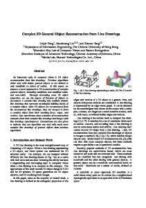
METHOD The first step is developing an appropriate elastic model of the region. Using a bathymetry map provided to us we generate a 25km x 25km x 2.5km elastic properties model by inserting water above the seabed and rock below it assuming a constant velocity gradient of 0.25/s from 2.25km/s at the shallow parts of the seafloor to 3km/s at the model base. We also include a single flat reflector at 1km depth, which represents a discontinuity of +250m/s in the velocity profile. The model has 2000 x 2000 x 400 grid points with 12.5m grid spacing laterally and 6.25m gird spacing vertically. The bathymetry model, presented in Figure 1, shows the continental shelf break running south-east to north-west across the model and a variation in water depth from about 50m on the continental shelf to 600m on the abyssal plain. The model includes
23 International Geophysical Conference and Exhibition, 11-14 August 2013 - Melbourne, Australia
1
Modelling complex wavefields, NW Australia
complex topography (including canyons) across the continental shelf break. The canyons’ dimensions are on the order of 250m deep, 600m wide, and 2km long. Figure 2 shows a cross-section of the model where the bathymetry drops from shallow depth on the continental shelf (right) over the continental shelf break with dips of up to 45º down to the abyssal plain (left). We model 3D wavefields using an elastic finite difference approximation with a staggered grid (Virieux, 1986). We utilise a velocity-stress formulation of the wave equation. The modelling is isotropic, uniform grid and accurate to secondorder in time and eighth-order in space. The top boundary is modelled as a free surface while the other boundary regions are modelled as perfectly matched layers (PML) (Collino and Tsogka, 2001). We modify their formulation by using a quadratically increasing damping factor rather than a constant one to reduce spurious reflections on the inside of the boundary. For our initial experiment we insert a 25 Hz Ricker wavelet as a plane wave 25m below the sea surface. The plane wave provides an initial examination of the topographic effects and is a first approximation to a brute stack from a single modelling run. The model time steps were 1ms and snapshots of the entire wavefield were output every 10ms. We ran the modelling on one node of our research group’s high performance computing cluster using 28 processors. The code is parallelised across multiple processors using OpenMPI.
Deeks, Lumley & Shragge
The second part of the wavefield that we analyse is the wave transmitted through the complex seafloor topography and flat reflector at 0.9s. Figure 4 shows an amplitude map of the transmitted wave. Regions of the wave near the continental shelf show variation of a factor of four in amplitude over distances of less than 500m, e.g. the region indicated by the 1km scale bar. Regions directly below the canyons have higher amplitude than the rest of the wavefront, while adjacent regions have relatively low amplitude. This demonstrates the significant focusing and defocusing which can extensively violate uniform illumination assumptions made explicitly or implicitly in seismic data processing algorithms. This also produces variability in the levels of illumination over different regions. These effects lead to low illumination below the canyons and render AVO analysis unreliable. Figure 5 is a three-dimensional image of the transmitted wavefield which shows the distortion through the canyons. This figure shows the top of the transmitted wave and we observe that it is very rugose with many discontinuities and breaks. We also observe apparent ‘ridges’ in the wave surface, these represent energy that is significantly delayed by the canyons and is no longer aligned with the main wave front. By using this modelling we observe directly low energy regions and other distortions in the wavefield. We hypothesise that since the canyon widths are on the same order of magnitude as the seismic waves they act as traps and waveguides, producing these effects.
CONCLUSIONS Our modelling results demonstrate the challenges presented by complex seafloor topography such as canyons. Such topographic features produce significant seismic wavefield distortions and illumination variations that issues for processing and analysing seismic data. Using highperformance computing facilities we model realistic effects of complex topography accurately and at high resolution for a better understanding of the effects. It also provides opportunity to benchmark different imaging/progressing algorithms and will assist us in developing improved imaging/processing algorithms.
ACKNOWLEDGMENTS
Figure 1: The bathymetry map used for the modelling in this project, clearly showing the canyons running across the continental shelf.
RESULTS AND DISCUSSION We analyse two aspects of the wavefield from this experiment. Figure 3 shows a cross-section from the reflected wavefield. These are the data that would be collected by a receiver array in a typical exploration scenario. We indicate the first arrivals from the seafloor reflection (A) and the flat reflector (B). Note that many seafloor multiples are visible on the left of the model due to the shallow water depth. We observe many diffraction hyperbolae and triplications such as that highlighted by the red circle, which provides evidence of complex wave multi-pathing.
rd
The authors of this paper would like to thank Lisa Gavin and Mohammad Emami for their assistance in interpreting and visualising the data and Woodside Energy Ltd. for providing the bathymetry map. We would also like to acknowledge the ASEG Research Foundation, the Robert and Maude Gledden Postgraduate Scholarship and the sponsors of the University of Western Australia’s Centre for Petroleum Geoscience and Carbon Dioxide sequestration (CPGCO2) for funding the research. This modelling was implemented using Madagascar (www.ahay.org).
REFERENCES Berryhill, J., 1986, Submarine canyons: Velocity replacement by wave‐equation datuming before stack: Geophysics 51, 1572-79. Bisley, R., and MacNeill, M., 2008, Application of true azimuth 3D SRME in the Northwest Shelf, Australia, 78th Annual Meeting, SEG, Expanded Abstracts, 2436-40.
23 International Geophysical Conference and Exhibition, 11-14 August 2013 - Melbourne, Australia
2
Modelling complex wavefields, NW Australia
Collino, F., and Tsogka, C., 2001, Application of the perfectly matched absorbing layer model to the linear elastodynamic problem in anisotropic heterogeneous media: Geophysics 66, 294-307. Debenham, H., and Westlake, S., 2012, PSDM for improved imaging under seafloor channels - Browse Basin, Australia case study, 22nd International Conference and Exhibition, ASEG, Brisbane, Expanded Abstracts.
Deeks, Lumley & Shragge
Dent, B., 1983, Compensation of marine seismic data for the effects of highly variable water depth using ray‐trace modeling—A case history: Geophysics 48, 910-33. Virieux, J., 1986, P-SV wave propagation in heterogeneous media: Velocity‐stress finite‐difference method: Geophysics 51, 889-901.
Figure 2: Cross-section of the elastic model with a single reflector at 1km depth.
A B
Figure 3: Cross-section of reflected wavefield, equivalent to a brute stack. The circle highlights a region where there is evidence of wave multi-pathing.
rd
23 International Geophysical Conference and Exhibition, 11-14 August 2013 - Melbourne, Australia
3
Modelling complex wavefields, NW Australia
Deeks, Lumley & Shragge
1 km
Figure 4: Amplitude map of the transmitted wavefield.
Figure 5: Three-dimensional image of the transmitted wavefield.
rd
23 International Geophysical Conference and Exhibition, 11-14 August 2013 - Melbourne, Australia
4