Gratis copy for Eric Armengaud Copyright 2011 SAE International E-mailing, copying and internet posting are prohibited Downloaded Tuesday, March 15, 2011 07:07:21 AM
Model-based Toolchain for the Efficient Development of Safety-Relevant Automotive Embedded Systems
2011-01-0056 Published 04/12/2011
Eric Armengaud and Markus Zoier Virtual Vehicle
Andreas Baumgart OFFIS e. V.
Matthias Biehl and DeJiu Chen Royal Institute of Technology
Gerhard Griessnig AVL List
Christian Hein and Tom Ritter Fraunhofer FOKUS
Ramin Tavakoli Kolagari
Volvo Technology Corporation Copyright © 2011 SAE International doi: 10.4271/2011-01-0056
ABSTRACT
INTRODUCTION
Advanced functionalities unthinkable a few decades ago are now being introduced into automotive vehicles through embedded systems for reasons like emission control, vehicle connectivity, safety and cooperative behaviors. As the development often involves stakeholders from different engineering disciplines and organizations, the complexity due to shared requirements, interdependencies of data, functions, and resources, as well as tight constraints in regards to timing, safety, and resource efficiency makes the system integration, quality control and assurance, reuse and change management increasingly more difficult. This calls for a more rigorous approach to the development of automotive embedded systems and components. This paper describes the CESAR reference technology platform (RTP) that supports the formalization of various engineering concerns in the development of safetyrelevant embedded systems and thereby a model-based integration of various tools and methods to form seamless environments or toolchains for the development of such systems.
Embedded systems are important innovation drivers in the automotive industry. They enable the introduction and improvement of advanced functionalities (e.g., active safety, fuel efficiency support) as well as the replacement of mechanical counterparts while saving weight and costs. At the same time, electronics components present strong requirements with regard to robustness and safety and the resulting system complexity is growing exponentially, which leads to increasing costs and tends to decrease the product quality. As most system development today is distributed across the boundaries of enterprises or engineering teams, it is critical that all system descriptions and information exchanges are precise enough but still with the possibility of protecting the intellectual properties (IP) of concern. For safety critical automotive embedded systems, an emerging standard is the ISO 26262 [12], which provides a reference lifecycle representing the domain consensus on the necessary information and workflow to achieve functional safety of E/E systems. All the aforementioned challenges and constraints for the automotive industry call for
2011-01-0056.indd 1
3/10/2011 3:32:36 PM
Gratis copy for Eric Armengaud Copyright 2011 SAE International E-mailing, copying and internet posting are prohibited Downloaded Tuesday, March 15, 2011 07:07:21 AM
a more rigorous approach to the system modeling, design, analysis, verification and validation than is the current state of practice for safety-relevant embedded systems. The CESAR project [10] has been started in that context to improve the engineering efficiency and effectiveness during the development of safety-critical embedded systems. Next to significantly improvements in tools and methods of the system engineering the R&D project relies on the development of an interoperability platform which is called the CESAR reference technology platform (RTP). The main contributions of this paper are (1) the description of the CESAR RTP concepts, (2) the discussion regarding the tailoring activities required for the deployment of a RTP instance, and (3) the illustration of the benefits from an industrial use case. The use-case is based on EAST-ADL [3], which is an architecture description language allowing the formalization of automotive embedded systems and thereby bringing a potential for a wide range of benefits in regards to system integration, quality control and assurance, and the creation of seamless toolchains for improving the development of safety-relevant automotive embedded systems. The paper is organized as follows: We first introduce the base technologies and their related state-of-the art approaches in the second section. The base technologies include: (1) the CESAR RTP concept, (2) the interoperability concept for model transformation and seamless tool integration and (3) the CESAR meta-model. Next, in Section 3, we discuss the tailoring activities required for the deployment of a RTP instance. The activities include (1) identification of the development process as well as tools involved, (2) integration of the foreign meta-models of involved tools by means of the CESAR meta-model, (3) development of tool adapters for expected tool interoperations, and (4) integration of the tool adaptation and interoperation components to form a modelbased integrated toolchain (tailored RTP instance). In the
fourth section, we show how the proposed CESAR RTP facilitates the system design with incremental verification and validation in a component-based development of automotive embedded systems. This is illustrated by an industrial scenario consisting of a system development performed by a dedicated toolchain (RTP instance). The last section concludes this work.
CESAR BASE TECHNOLOGIES AND STATE OF THE ART THE CESAR RTP CONCEPT
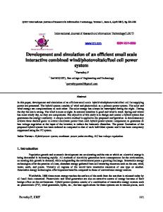
The CESAR project is a European project funded from Artemis JU and national authorities and regroups 55 partners with a global budget of 58 M€ and a cumulated effort of 427 man-years over a duration of three years. CESAR’s main objective is the reduction of cost for the development of safety-critical systems by improving the processes and methods for design decisions, analysis and V&V, reuse and change management. The CESAR RTP aims to facilitate the creation of integrated development environments and toolchains for various application domains. Furthermore, the CESAR project also aims to bring significant innovations in the following two fields: (1) requirements engineering, in particular by formalizing multi-viewpoint, multicriteria, and multi-level requirements, and (2) component-based engineering applied to design space exploration comprising multi-view, multi-criteria and multi-level architecture trade-offs. These innovations are driven - and will be validated - by pilot applications from the domains of automotive, aerospace, rail and automation respectively. The RTP is a generic model-based integration platform providing a conglomerate of modules that can be combined in different ways in order to provide a seamless development environment (RTP instance) tailored to one specific product development process (see Figure 1). The combinable modules
Figure 1. The CESAR RTP concept
2011-01-0056.indd 2
3/10/2011 3:32:37 PM
Gratis copy for Eric Armengaud Copyright 2011 SAE International E-mailing, copying and internet posting are prohibited Downloaded Tuesday, March 15, 2011 07:07:21 AM
can either be approved commercial-of-the-shelf (COTS) tools, innovative outcomes of research projects, meta models, tool integration frameworks or supporting services. The subset of required entities can be defined using tailoring rules according to relevant safety standards (e.g., ISO 26262, EN 50128), application domain (e.g., automation, aerospace) or companyspecific habits (e.g., preferred tools, customized processes). Depending on these rules, a process-driven tailoring of the RTP can be performed. The tailoring step comprises the generation of a customized integrated tooling environment tailored to relevant safety standards, application domain and company habits. This generation comprises activities like tool installation, deployment of adapters for the integration of toolspecific meta-models, and instantiation of a process manager according to company-specific process needs. The result of the RTP tailoring step is the RTP instance (toolchain). It consists of a set of communicable and interoperable engineering tools as well as the RTP-ModelBus [11] being in charge of the communication between these tools. While each tool is used to support certain design, analysis, and synthesis activities in one or multiple system refinement steps, the ModelBus helps to ensure the data consistency and traceability among different tools. To this end, a dedicated meta-model for this RTP instance is derived from the CESAR meta-model and used to manage interchangeability between the tools by mapping their internal model representations and semantics to a commonly agreed basis. Connections to the RTPModelBus are either realized via adapters performing modeltransformation (in order to convert tool-internal model representations into the RTP meta-model in case of a toolspecific data format), or directly integrated to the RTP metamodel (when the tool provides a data format compatible with the RTP meta-model). Analysis tools (such as [17]) are connected in the same way. Existing approaches to interoperability and tool integration for safety-critical embedded systems development are evolving [2, 18] and often academic [7, 8]. However, CESAR aims at achieving a common understanding and an agreement on concepts for interoperability and tool integration for safetycritical embedded systems development between industrial and academic key players in the automotive, aerospace, automation and rail domains. Moreover CESAR aims at a flexible approach where both, solutions of vendors and SMEs as well as open-source solutions can compete in offering best-in-class solutions for particular stages of these processes. This approach is based on cross-domain commonalities in the development processes for safety-critical embedded systems. In order to gain acceptance of industrial stakeholders and tool vendors, the RTP needs to support integration of existing tool frameworks, often equipped with own meta-models, as well as requirement and configuration management facilities. Thus, the implementation of the RTP instance is strongly driven by
2011-01-0056.indd 3
the need to identify common aspects in these environments, to provide a consistent view based on them, and to make them available to design, analysis and validation methods. This is facilitated by the development of a proper meta-model for the RTP instance. Thus CESAR fully considers the strong and ongoing trend towards meta-model based tool integration of recent research activities [16].
THE CESAR MODELBUS AND RELATED INTEROPERABILTY CONCEPTS OF INTEGRATED TOOLCHAIN TECHNOLOGIES
In large distributed development environments the consistency of data and processes as well as the synchronization of the communication among the stakeholders is a challenging task. The complexity of efficient tool interaction (orchestration, control, integration) grows with the number of tools involved. The problem domain of tool integration and its theoretical reasons have been identified and discussed from different viewpoints. Wassermann [24] identified five dimensions of tool integration: (1) Data integration shares the data produced by different tools and manages the relationship between the data objects. (2) Control integration allows tools to notify and activate other tools. (3) Presentation integration provides a common user interface with a common look-and-feel. (4) Process integration provides process management tools with data from development tools. (5) Platform integration provides a virtual operating environment for heterogeneous hardware and software. This has been further elaborated later by Thomas and Nejmeh [22] where they emphasized the role of framework services and integrative environments. In a very similar way, the “Toaster Model” of the European Computer Manufactures Associations (ECMA) [25] addressed this problem domain. From a practical point of view tool integration is still an open issue. There are a number of vendor specific or point to point integration. Such integration solutions allow the sharing of data among different tools by simple import and export commands using proprietary file formats synchronized via a file system. These solutions work usually only for a limited part of the process and binds the stakeholders to the respective vendor. There are more general approaches to that, often named as Application Lifecycle Management (ALM), but mostly with special emphasis on change management, traceability and reporting. There are communities such as the Open Services for Lifecycle Collaboration initiative, which targets on the definition of vendor-neutral tool interfaces based on Representational State Transfer (REST) for ALM solutions. Apart from ALM, the Eclipse IDE as tool integration platform is in particular strong in the presentation integration aspect (third aspect listed in the previous paragraph). Eclipse IDE is a diverse and flexible solution, which comes with many extensions build by Open Source communities and vendors
3/10/2011 3:32:37 PM
Gratis copy for Eric Armengaud Copyright 2011 SAE International E-mailing, copying and internet posting are prohibited Downloaded Tuesday, March 15, 2011 07:07:21 AM
addressing some of the other integration aspects listed before as well. However, all solutions do have drawbacks, which make it hard to use them in a scope that is addressed by the CESAR project. Therefore, CESAR has defined an interoperability specification, which addresses all relevant aspects of tool integration. This specification defines how tools interact, by defining communication standards and protocols, basic infrastructure services, and data definition and handling. So the CESAR approach is vendor neutral, provides a comprehensive view on the tool integration dimensions and allows the flexible creation of development solutions which take the specifics of the stakeholder’s development environment, organizational structures and existing tool landscape into account. The RTP-ModelBus realizes this interoperability specification. It creates a virtual bus topology connecting tools being part of a certain development environment forming an RTP-instance. This comprises tools of potentially all development phases including process steps as requirements engineering, system architecture design, coding, testing or even reporting. The set of tools used in typical development processes can be quite diverse and may contain COTS tools as well as custom made or in-house proprietary ones. The important point about the interoperability specification and the RTP-ModelBus is that it uses existing methods and approaches in order to avoid building everything from scratch and to combine everything in a coherent way. RTP-ModelBus is taking a service-oriented approach into account (SOA - define the interfaces in terms of protocols and functionalities, thus enabling loose coupling between the
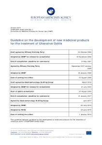
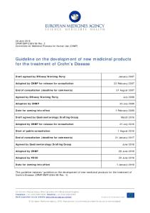
connected tools and services as illustrated in Figure 2). Additionally, only open standards with available implementations are used in ModelBus. Tools connected to the ModelBus provide or consume services that contribute to the system development process. These services can be very different in nature. A service can be a report generator, an analysis tool, or a simulation engine, e.g., executing long running simulations. There are client tools, which are used by humans and which usually offer a graphical user interface and there are server tools, which provide a specific functionality and which are not necessarily equipped with a graphical user interface. Of course these categories are not completely disjunctive since a tool may run in batch or server mode while it provides other parts of its functionality via a graphical user interface. The problem of data integration is solved by ModelBus in a particular way. ModelBus uses models for exchanging data. So any externalized information (provided or consumed via services) is translated in a common representation framework, which is based on meta-modeling principles. This allows a tool-neutral and technology-agnostic handling of the exchanged data. Of course ModelBus can also handle data, which is not represented as model, such as source code or binary files. ModelBus is using an interaction pattern for realizing the actual exchange of data. This interaction pattern is formally defined and is based on a repository service. With this a tool can easily address an arbitrary model (or any other piece of data) just by using its reference. ModelBus does an automatic lookup and fetches the model from the correct repository. The interaction pattern is outlined in Figure 3 and described also in [11].
Figure 2. ModelBus overview
2011-01-0056.indd 4
3/10/2011 3:32:37 PM
Gratis copy for Eric Armengaud Copyright 2011 SAE International E-mailing, copying and internet posting are prohibited Downloaded Tuesday, March 15, 2011 07:07:21 AM
Figure 3. The ModelBus Interaction Pattern
ModelBus is also concerned with the automation of the development process. Certain generic platform services are being used, including an orchestration engine, user & rights management, version & configuration management, and traceability management. The automatic execution of service invocations can be triggered by certain events. Such events can be the provision of a new model or just a new version of a model. ModelBus uses an event distribution service for the realization of the automation. With the help of the automation capability ModelBus offers an additional working mode. A client tool does not necessarily invoke remote services directly, instead it may simply provide its data to the ModelBus and this triggers automatically the invocation of a service. Both working modes (i.e. direct or indirect) can be used in parallel. This helps to create a flexible solution, which fits to the needs of the development process, meets the requirements of the stakeholders, and takes the characteristics of the involved tools into account.
THE CESAR META-MODEL (CMM)
The CESAR project evaluates a common meta-model approach to enable harmonized interoperability between tools and services with heterogeneous data models. It targets to develop a CESAR meta-model (CMM) with common domainindependent meta-model concepts that is modular extendable and which is intended to be used as common meta-model for an RTP instance with an interoperability framework like ModelBus [11]. The CMM therefore provides a harmonized common understanding of data concepts as well as data artifacts and their relationships for the interoperability and integration of tools with heterogeneous data models [17]. In CESAR a multi-domain reference technology platform (RTP) is developed, which can be instantiated for various industrial development processes in safety-critical embedded system design like in avionics, automotive and automation. To enable data interoperability with several integrated tools and services the identification and definition of common meta-model concepts for multiple viewpoints and along all levels of development processes is a crucial point. Based on these common concepts, a domain-, tool- and company-independent and commonly understandable data structure is provided, which can be used for data exchange and analysis increasing
2011-01-0056.indd 5
tool reuse independent of specific domains and improving integration. The CMM is based on results of European research projects, in which widely usable meta-model concepts were developed, such as EAST-ADL from the ATESST series projects [3] and HRC from the SPEEDS project [20]. The basis of the CMM is an integration of HRC Level 1 Kernel as well as common domain-independent meta-model concepts from EAST-ADL and those developed and identified in CESAR. EAST-ADL complements the HRC/SPEEDS approach with automotive domain-specific concepts regarding architecture, verification and validation, abstraction levels, and lifecycle information. The CESAR meta-model concepts furthermore consider generic component-based design along embedded system development processes with informal as well as formal requirements using different kinds of requirement specification languages (RSL) and traceability management [11].The CMM is therefore intended to support multi-viewpoint component structure modeling along a multilevel development process with requirements, traceability, error modeling as well as verification and validation. It is not a conglomeration of various artifacts to cover everything from all tools and domains because such a meta-model would be giant, unusable and not maintainable [5]. Thus, it provides artifacts with respective relationships to cover common metamodel concepts, which are independent of specific tools and domains. The current CMM provides core concepts to describe systems along several levels of abstraction by using models with multiple viewpoints on requirements, components as well as V&V cases with respective means of traceability. The CMM enhances HRC components and allows distinction between functional and different kinds of component models. Informal as well as formal requirements based on contracts can be defined and linked to components, requirements and verification and validation entities.
HRC - Heterogeneous Rich Component model HRC [21] is a meta-model for rich component design supporting modeling and analysis of complex embedded systems by using formal analysis tools. It enables a generic
3/10/2011 3:32:37 PM
Gratis copy for Eric Armengaud Copyright 2011 SAE International E-mailing, copying and internet posting are prohibited Downloaded Tuesday, March 15, 2011 07:07:21 AM
and formal description of components, their decomposition, interfaces and assumed as well as promised behavior in terms of contract-based design. The HRC meta-model provides concepts for component structures, component behavior as well as an expression and action language. Structurally rich components are component types that can be decomposed by defining rich component properties respectively typed by rich components. Rich components have ports, which are typed by port specifications that contain data flows or provide respectively require services which is compliant to ports defined in UML/SysML [14]. Rich component dynamics can be formally described by using state machines and contracts. Contracts are pairs of assumptions and promises. An assumption describes how the component’s context is considered to behave and the promise describes how the component behaves if the assumption is fulfilled. HRC state machines allow the description of rich component behavior as hybrid automata [6]. The HRC expression and action language defines datatypes, expressions and actions. HRC data types allow the description of highly complex data structures as they are known from common programming languages like e.g., C. Furthermore, primitive types can be used with additional dimensions and units to describe physical types [5]. HRC expression language allows formal descriptions of data content (i.e., values or conditions) based on simple values, their combination and referenced structural data items, functions and actions. The action language provides a means for statements in terms of imperative programming to describe function bodies, service implementations or actions of state machine transitions.
EAST-ADL One base technology for the CMM is the EAST-ADL, which aims to provide a well-defined information infrastructure for capturing, evaluating, and managing various engineering concerns across system development stages [3]. The language is aligned with ISO 26262 [12] for functional safety of automotive embedded systems in regards to the work flow and information management. The core of EAST-ADL is its support for system architecture description with models on multiple levels of abstraction according to the needs of separation of concerns in the automotive domain. The topmost system description is performed at Vehicle Level capturing the features of an automotive product family. In EAST-ADL, a vehicle-level feature typically represents an end-to-end system functionality (e.g., braking), while a feature in general refers to a trait or characteristic that a system may or may not have. To satisfy certain requirements, a vehicle-level feature obeys
2011-01-0056.indd 6
constraints on its behavior (e.g., I/O operations, environmental conditions, and vehicle modes), timing (e.g., end-to-end delay), as well as safety (e.g., the deduced safety goals). By means of feature models, one can specify the allowed variability and inheritance hierarchy, which for example running from vehicle longitudinal control feature to braking and retardation features. The realization of a Vehicle Level feature is supported by logical artifacts, specifying for example the implied functions for sensing, controlling, and actuation in feedback control loops. In EAST-ADL, the design of such logical artifacts is first captured by a Functional Analysis Architecture and thereafter detailed by a Functional Design Architecture at Design Level. It is at the Design Level that the characteristics of system resources as given by the Hardware Design Architecture are taken into consideration. Typical design decisions then include the partitioning and allocation of logical functions on hardware resource. Finally, the Implementation Level specifies the actual software and hardware configuration according to AUTOSAR [4]. EASTADL provides dedicated language support for capturing the realization hierarchy from Vehicle Level features to Implementation Level solutions. Similar as in SysML [14], each requirement in EAST-ADL can be traced to its derived subrequirements, implied verification and validation (V&V) cases, system artifacts providing the satisfaction, or detailed information about the implied parameters, states, operations, and vehicle modes. As shown in Figure 4, EAST-ADL allows the elements of a System Model to be associated with a set of models capturing the related requirements, verification and validation cases, environmental concerns, and constraints in regards to behavior, timing (e.g., rate and synchronization constraints), variability, and dependability. For example, a behavior model of EAST-ADL can be used to define the vehicle modes, parameter ranges, operation states as implied in textual requirements, as well as the external descriptions (e.g., in Simulink/Matlab) of computations to be implemented by a system function; a dependability model augments the core system model with the descriptions of hazards, failure modes, and error propagation and the derived safety goals and constraints [19]. Current EAST-ADL support for timing incorporates the results of the ITEA2 project TIMMO [23], which provides a formal description language and methodology for dealing with the timing concerns. The EAST-ADL language can be implemented as a UML profile and thus supported by various UML modeling tools. Further harmonization is being carried out with the aim of releasing the EAST-ADL profile as an annex to the subsequent version of MARTE [13].
3/10/2011 3:32:37 PM
Gratis copy for Eric Armengaud Copyright 2011 SAE International E-mailing, copying and internet posting are prohibited Downloaded Tuesday, March 15, 2011 07:07:21 AM
Figure 4. An overview of modeling scope and levels-ofabstraction by EAST-ADL
TAILORING ACTIVITIES FOR THE DEPLOYMENT OF A RTP INSTANCE OVERVIEW
The tailoring step regroups all the activities required for the instantiation of a dedicated toolchain for a specific purpose, see Figure 1 and Section II-1: CESAR RTP concept. In this
Section, we discuss the activities required for the tailoring of the generic assets (e.g., meta-model, tool adapters, data backbone). Figure 5 illustrates the four main tasks required. The first step of the tailoring activities consists of the definition of the development process and the decision of the required development steps and respecting tools. This includes further the deployment of the data backbone (ModelBus) and its configuration according to the tools to be integrated, the design of a workflow as interaction pattern of the platform services (orchestration) and model-transformation services required. The second step concerns the definition of the product metamodel and regroups two sub-activities. The first sub-activity is the identification of the data structure according to the included development steps, the respective viewpoints modeled and the tools involved. This data structure is a union of all the data structures of the tools involved. The second sub-activity is the identification of the required traceability links. These links (especially across the tools) define the relations between the development steps and therefore the required model transformations. The third step consists of the implementation of the specific tool adapters. Such tool adapters provide standard services for the integration to the ModelBus (e.g., check-in, check-out), as well as syntactic and semantic transformation in order to map the tool-specific data to the RTP instance. The last step concerns the evaluation of the integrated toolchain according to typical product development activities.
Figure 5. The four different tasks for the development of an RTP instance
2011-01-0056.indd 7
3/10/2011 3:32:38 PM
Gratis copy for Eric Armengaud Copyright 2011 SAE International E-mailing, copying and internet posting are prohibited Downloaded Tuesday, March 15, 2011 07:07:21 AM
META-MODEL INTEGRATION
The CESAR meta-model (CMM) is intended to be used as a shared common model of data in an interoperability platform for tools with heterogeneous data sets. Such data sets have their own types and meta-models such as EAST-ADL. Thus, one crucial issue to enable interoperability among tools in a tailored RTP is the integration of foreign meta-models and to make them compatible with the common meta-meta of the RTP, the CMM. The most important step of such a meta-model integration in a tailoring process is to define a mapping between the foreign meta-model and the CMM. This enables common understanding of the foreign meta-model within the RTP using the CMM. A mapping can be defined in a human readable form like a table. The mapping defines how foreign meta-model concepts with their elements and relationships can be mapped to those of the CMM having common semantics. In addition to the elements and references to other elements a mapping of all information such as the possible number of referenced elements is important for implementation decisions. I.e. for the mapping of the decomposition of EAST-ADL Analysis Function Types the element “AnalysisFunctionTypes”, its reference “part”, the referenced element “AnalysisFunctionPrototype” and the possible number of referenced Analysis Function Prototypes “0..*” (arbitrarily many referenced elements) have to be listed. Non-trivial mappings regarding combinations of elements and surjective mappings where one element is mapped to one of many elements can be described the following way. Table 1-1 shows an exemplary mapping between EAST-ADL and the current CMM. This table lists how EAST-ADL and CMM concepts relate to each other and therefore how metamodel elements and relationships can be mapped. For each mapped meta-model concept the respective element name, reference name, referenced element and the possible number of referenced elements are listed. Some mappings are trivial such as RichComponent part and AnalysisFunction part because RichComponent and AnalysisFunction as well as RichComponentProperty and AnalysisFunctionPrototype can be mapped to each other providing decomposition of components. The part property of AnalysisFunctionType has the same multiplicity and the mapped property type is the same as for Rich Component part. When mapping the execution semantics of EAST-ADL function types with run-tocompletion semantics being aligned with AUTOSAR to rich component dynamics, this behavior has to be expressed in terms of CMM behavior and contracts, which describe the dynamics of a rich component. In order to make the mapping of the foreign meta-model usable within the RTP an implementation is needed. Concrete implementations depend on the tools being involved and the development process. In the following we describe two reference implementations of meta-model integration along with EAST-ADL and HRC, which were created within the CESAR project and describe harmonized CMM based interoperation between tools with heterogeneous data-models in an instantiated RTP using tool
2011-01-0056.indd 8
adapters. Both implementations are based on the same mapping, which had to be defined first. For RTP version 1.0, EAST-ADL and HRC were integrated and therefore mapped to the CMM. This enables harmonized CMM based interoperability between tools and analysis services that use these meta-models like Papyrus with EASTADL plugin [15] and an HRC based virtual integration testing service from SPEEDS project [20] in an instantiated RTP, which is exemplarily shown here. Since function types and hardware elements in EAST-ADL provide compositional structures with typed interfaces, respective connections and behavior, these concepts can be mapped to rich components, rich component properties, ports, interconnections and behavior. Furthermore there are special requirements and trace links which can be identified by concepts of the CMM like requirement, satisfy link, derive link etc [5]. EAST-ADL abstraction levels and contained models provide model container and can therefore be mapped to CMM declaration zones that provide generic concepts of abstraction levels and rich component models. Since the CMM widely consists of HRC concepts HRC mapping is mainly trivial. Rich component structures and datatypes can be directly mapped. But HRC contracts belonging to rich components are mapped to CMM rich components satisfying system requirements in CMM. EAST-ADL is implemented as a UML profile in the Papyrus tool. Thus, for RTP 1.0 a first implementation of EAST-ADL mapping was created by enhancing a CMM UML profile implementation with EAST-ADL stereotypes specializing CMM stereotypes to cover EAST-ADL-specific information related to the common concepts. Stereotype properties were replaced by respective CMM stereotype properties, they were declared “redefining” when associating other specialized stereotypes respectively with different multiplicities or they were declared “subsets” when denoting subsets of CMM stereotype properties. This implementation allowed export of EAST-ADL models in Rhapsody with a tailored EAST-ADL profile to HRC models for formal analysis. A second implementation of EAST-ADL and HRC tailoring to concepts of the CMM was created by performing model transformation between UML with EAST-ADL profile and HRC. Here the identified common concepts of UML with EAST-ADL profile and HRC were used to define QVT transformation rules [5]. Using this technique in a CESAR scenario EAST-ADL structure was enhanced by formal contracts and afterwards formally analyzed by using a virtual integration testing service as defined in SPEEDS project [20]. When an RTP is instantiated a meta-model and an interoperability platform are chosen. The CMM and ModelBus [11] are intended to be used for that purpose. In order to connect tools from a tool chain and services to the interoperability platform in the instantiated RTP tool adapters are chosen. These tool adapter encapsulate an implementation of the mapping between the respective tool data model and the
3/10/2011 3:32:38 PM
Gratis copy for Eric Armengaud Copyright 2011 SAE International E-mailing, copying and internet posting are prohibited Downloaded Tuesday, March 15, 2011 07:07:21 AM
Table 1-1. Mapping table for EAST-ADL and the CMM
meta-model of the RTP instance. In the interoperability platform there can be several data repositories available which are provided by the connected tools or by the interoperability platform itself. On the one hand the CMM or the respective RTP meta-model can be used by the tool adapter as a native data format for data storage in a connected data repository. On the other hand the tool-adapters can store native tool data to an available RTP repository and provide an RTP meta-model view on this data as described in [5]. Using the RTP common meta-model the heterogeneous data of different tools which is available in the RTP can be accessed from all connected tools and data items can be linked to each other in a harmonized data view. Thus, as a conclusion the integration of foreign meta-models in an RTP tailoring process and the definition as well as the implementation of mappings to the CMM enables common understanding without the concrete knowledge of these metamodels in all tools of the RTP instance. The definition of the mapping between artifacts and relationships of a foreign metamodel and the CMM is very important. Such a mapping can be implemented in several ways to have common understanding of foreign data that is communicated in the RTP instance. In order to enable a harmonized CMM based interoperation between tools with heterogeneous data-models in an instantiated RTP the implementation of a mapping between a tool data-model and the CMM is encapsulated in a tool adapter
2011-01-0056.indd 9
which can be chosen for the connection of the respective tool to the RTP.
TOOL ADAPTER
In terms of the CESAR approach a tool adapter is needed in order to connect a tool to the RTP-ModelBus. However, there is no universal adapter available that can be used for every tool. An adapter is in most cases specific and it may even be possible that several adapters are needed for the same tool. For example, a text processor tool can be used as requirements specification tool as well as an analysis reporting tool. The relevant data to be exchanged is different in both cases and the adapter can be specific for each purpose. Therefore, an adapter has to take care of the syntax, semantics and operational aspects of the tool and the tool data. In order to implement an adapter a couple of general architectural decisions needs to be taken. At first, it needs to be decided how the tool should interact with others in an integrated toolchain and e.g., whether the tool is used as client or as server tool. A server tool may need to offer specific functionality (e.g., automated execution of a simulation run). In this case a service interface needs to be defined and a server adapter has to be created. If the tool is a client tool (i.e., humans are interacting with it) it has to be decided whether the tool only publishes its internal data to the ModelBus (which may trigger automatic invocation of other services) or whether the tool is about to invoke additionally a
3/10/2011 3:32:38 PM
Gratis copy for Eric Armengaud Copyright 2011 SAE International E-mailing, copying and internet posting are prohibited Downloaded Tuesday, March 15, 2011 07:07:21 AM
remote service. In order to publish the data to ModelBus only, the tool adapter simply needs to use the ModelBus API for storing a model. For invocation of a remote service the adapter has to implement a client for the respective service interface. Before actually starting the definition and implementation of adapters, another aspect needs to be considered: It has to be decided which data (models) shall be exchanged. Shall a tool export its complete data or shall it export just a subset of it? The CESAR project tries to harmonize the data structures by defining a common meta-model (CMM). So a tool may exports its data adhering to that meta-model, when the adapter is newly created. On the other side existing adapters may export data conforming to other meta-models. In such case a model transformation which translates from the tool specific model into the common meta-model is needed. Such a model transformation can be executed automatically within ModelBus, whenever a new model is exposed. The following paragraph outlines the general tasks to accomplish in order to create a tool adapter.
Definition of the Service Interface: The easiest way to define a service interface is to use the Java language. For doing so just a Java interface needs to be defined. In this Java interface the concrete model types can be used. By using the ModelBus SDK (based on DOSGI1) a web service description language based interface description is derived implicitly when appropriate annotations are being used. The following example shows the definition of a simple service interface containing a service that adds a writer to a library. The service and the client can be implemented using different technologies as long as the ModelBus interaction pattern is respected. ModelBus is providing skeletons for Java and for . Net. The following code fragment shows the implementation of the service. The implementation of a data provider for a client tool is very similar. The only difference is that the service interface is already fixed and implemented by the ModelBus repository service. The usage is simple: A session object containing user credentials needs to be created for getting access to the user repository.
1 www.dosgi.com
2011-01-0056.indd 10
3/10/2011 3:32:38 PM
Gratis copy for Eric Armengaud Copyright 2011 SAE International E-mailing, copying and internet posting are prohibited Downloaded Tuesday, March 15, 2011 07:07:21 AM
The next step is the integration of the adapters and the respective tools. The realization of adapters can be different and is dependent on the tool. Many COTS tools provide a plug-in mechanism, which allows the integration of ModelBus adapter code in the host tool in an easy way.
INTEGRATION IN MODELBUS AND COMPLETION OF THE TOOLCHAIN
Combining all entities to an integrated development environment takes several steps. The first step is the setup of the generic ModelBus platform. It operates as data backbone connecting all internal services (like transformation services, orchestration, and security) and external services (mainly the tools connected by tool-adapters) necessary for the desired development process. These services and the ModelBus itself are usually deployed on a dedicated server machine running a web application server like Apache Geronimo2. In the second step tool adapters are provided to the tools fulfilling the development process. Tool adapters can extend tools by acting as plug-ins or being standalone applications connecting the data management of the tool (usually running on the computers of the development engineers) with the ModelBus platform using a local computer network. The third step is the configuration of the platform services. Providing the necessary transformation rules (e.g., modeled in QVT3 or ATL4) to the transformation services is the most important step to enable the model-based data exchange. This also includes the configuration of the traceability management. To automate certain parts of the development process and platform background activities, a workflow is designed by a BPMN orchestration scheme5 as interaction pattern of the platform services. This orchestration scheme is a breakdown of the development work flow to the level of the services and data elements. Now the toolchain setup is completed. To evaluate the tool interaction, reference data (examples of data from development process) is provided by executing the desired development process. Comparing the provided integrated solution to a straight pointto-point integration of the tools using connectors it is obvious that the direct connection of tools leads to conversion instructions that are separated over several connectors and do not follow an overall pattern. The information exchange between different development activities across development phases is difficult to implement. The communication to activities linking to multiple steps of the development process like requirements- or workflow
management is difficult to implement. If an engineering department is running multiple projects at the same time, direct connections get inflexible and are difficult to handle. An integrated solution using a common, model based scheme allows a concentration of all conversation instructions in the platform following one generic concept (meta-model of the RTP instance) and using standardized interfaces.
USE-CASE: AUTOMOTIVE TEST MANAGEMENT TOOLCHAIN A demonstrator has been implemented in order to illustrate our claims, see Figure 6. The motivation for the integrated toolchain is to support the interactions between the roles of requirements engineer, system engineer, V&V manager and test engineer. The toolchain includes the connection of the tools Papyrus6 and the AVL InMotion7 using the RTP-ModelBus presented in Section 2. Papyrus, on one side, is an open-source tool that supports the modeling of automotive embedded systems according to EAST-ADL. AVL InMotion, on the other side, is a real-time simulation platform for maneuver and event-based testing at the test bed. In combination with AVL Cruise5, it supports key business objectives such as hybridization and electrification of power train engineering. For the evaluation, a recuperation function for a hybrid vehicle has been used. Recuperation is the recovery of kinetic energy by the e-motor operating in generator mode. Here the e-motor generates a negative torque that decelerates the vehicle and is transformed into electrical energy that is used to charge the batteries and to supply the conventional low voltage board net with electrical energy. The system regroups 28 requirements and can be decomposed into five sub-components. Two test campaigns have been developed to test the requirements. Seven test cases have been automatically derived from these two test campaigns. Figure 7 provides an overview of the resulting model and the mapping with the development activities. During the first step, the system requirements are modeled (RECUP) and refined (RECUP1 and RECUP2). During the second step, the system architecture is defined (Hybrid Control Unit, E-Drive) and the traceability links are added. The third step consists of the description of the test cases (TestCase RECUP1 Motoring, TestCase RECUP2 Recuperation). It includes links to a reference test case consisting of the description of the car, its behavior and the environment as well as variation parameters for the car behavior (e.g., car acceleration or pressure on the
2 http://geronimo.apache.org/ 3 QVT = Query/View/Transformation, http://www.omg.org/spec/QVT/ 4 ATL = Atlas model transformation language, http://www.eclipse.org/atl/ 5 www.bpmn.org 6 papyrus-uml.org 7 www.avl.com, AVL InMotion powered by IPG CarMaker
2011-01-0056.indd 11
3/10/2011 3:32:38 PM
Gratis copy for Eric Armengaud Copyright 2011 SAE International E-mailing, copying and internet posting are prohibited Downloaded Tuesday, March 15, 2011 07:07:21 AM
brake pedal). These three first steps are performed in the Papyrus tool according to the EAST-ADL methodology. The fourth step is the model transformation from EAST-ADL to the AVL InMotion tool. The variation parameters described in step three are the inputs to generate automatically an InMotion test case for each parameter variant. In the fifth step, the test cases are implemented in the corresponding test environment and executed. The results are then transformed back to the Papyrus tool (step six). During this InMotion to EAST-ADL transformation, the test execution status and a link to the test results from InMotion are automatically inserted into the EAST-ADL model. Finally the results are available for analysis for the V&V manager (step seven). The main benefits of the proposed integrated tool-chain for the recuperation function are the following: • Explicit annotation of the system architecture using a semiformal language (EAST-ADL). This minimizes the ambiguity of the system being developed and simplifies synchronization between large teams (multi-site collaboration). Furthermore, the formalization provides a solid basis for further static analysis (e.g., completeness checks: are all the components mapped to requirements and test cases?). The modeling of the system using EAST-ADL has enabled a fast synchronization of our 15 person team across three countries. • Traceability between requirements, system components, test cases and test results. Thanks to the meta-model covering the entire development process, all the activities are related together and the collaboration between the different
experts is strongly improved. During our evaluation, the misunderstandings between the different experts and work steps have been strongly reduced thanks to the complete overview of the development status. • Easy extension of the current toolchain. The availability of a vendor-neutral data backbone with standardized services as well as common understanding on the data thanks to the CESAR meta-model makes the enhancement of the toolchain quite easy. Hence, further tools (e.g., for system design, analysis or validation) can be integrated on the platform later on. • Automated notification when the system has been modified and a new task should be performed. This supports the coordination within the team. • Automated configuration of following development steps. Consecutive development steps usually represent a refinement of the abstract model down to a specific implementation and its corresponding validation. Results of a development steps can be used as input for the following development step. When different tools are used, the configuration has to be performed manually, which is error prone. Model transformation with tool adapters enables the automation of data transfer, thus reducing development time and minimizing human error. During our evaluation, model transformation has been used (1) for automated test case generation out of the test campaigns and (2) for mapping the test results back to the system description. These transformations have saved engineering time and have minimized human error.
Figure 6. RTP instance for automotive test management scenario
2011-01-0056.indd 12
3/10/2011 3:32:39 PM
Gratis copy for Eric Armengaud Copyright 2011 SAE International E-mailing, copying and internet posting are prohibited Downloaded Tuesday, March 15, 2011 07:07:21 AM
Figure 7. Model overview of the product development
SUMMARY/CONCLUSIONS Due to its size and relevance of the partners, the CESAR project provides a platform to enable different technologies coming both from industry and research projects - to converge. The focus is set to the cost-efficient development of safetyrelevant embedded systems. During this work, the CESAR RTP as central concept of the project has been discussed. Deployment of a dedicated RTP instance regroups four tasks which are: 1. identification of the development process as well as tools involved, 2. integration of foreign meta-models to be mapped to the CESAR meta-model, 3. development of tool adapters, and 4. integration of the components into a modelbased integrated toolchain (tailoring RTP instance). These four tasks are difficult to coordinate since they regroup different expertise ranging from domain-independent software engineering up to domain-(tool-)specific meta-models. The resulting toolchain, however, strongly improve product development from the following point of views: 1. traceability between the system artifacts (e.g., between requirements, components, test cases) and therefore improvement of product quality, 2. improved tool integration and therefore better cooperation between development steps requiring different tools and expertise, thus saving development time, and 3. advanced integration platform supporting the integration of automated services (such as static analysis or automated documentation generation).
REFERENCES
2. Altheide, F., Dörfel, S., Dörr, H., Kanzleiter, J.: An architecture for a sustainable tool integration. In: Proc. of the Workshop on Tool Integration in System Development, European Software Engineering Conference (TIS 2003). (2003) 29-32 3. The ATESST2 Consortium. EAST-ADL Domain Model Specification. Advancing Traffic Efficiency and Safety through Software Technology (ATESST). EUROPEAN COMMISSION FP7 Grant Agreement 224442. 2010.
4. AUTOSAR Development Partnership, http://www.autosar. org 5. Baumgart, A. A common meta-model for the interoperation of tools with heterogeneous data models, Proceedings of the 3rd Workshop on Model-Driven Tool & Process Integration (MDTPI, 2010): 6. Baumgart, A.; Reinkemeier, P.; Rettberg, A.; Stierand, I.; Thaden, E.; Weber, R.: A Model-Based Design Methodology with Contracts to Enhance the Development Process of Safety-Critical Systems : Proceedings of 8th IFIP Workshop on Software Technologies for Future Embedded and Ubiquitous Systems (SEUS, 2010) 7. Burmester, S., Giese, H., Niere, J., Tichy, M., Wadsack, J., Wagner, R., Wendehals, L., Zündorf, A.: Tool integration at the meta-model level: the fujaba approach. International Journal on Software Tools for Technology Transfer (STTT) 6 (2004) 203-218
1. AADL - Architecture Analysis & Design Language, http:// www.aadl.info
2011-01-0056.indd 13
3/10/2011 3:32:39 PM
Gratis copy for Eric Armengaud Copyright 2011 SAE International E-mailing, copying and internet posting are prohibited Downloaded Tuesday, March 15, 2011 07:07:21 AM
8. Burmester, S., Giese, H., Hirsch, M., Schilling, D., Tichy, M.: The fujaba real-time tool suite. In: Proc. of the 27th International Conference on Software Engineering (ICSE 2005). (2005) 670-671 9. Earl, A.: Principles of a reference model for computer aided software engineering environ-ments. In Ling, F, editor, The international Workshop on Environments (Software Engineering Environments), volume 647 on Lecture Notes in Computer Sciences, pages 115-129, Springer-Verlag, Berlin, September 1989, Chinon, France 10. Griessnig, G., Mader, R., Peikenkamp, T., Josko, B., Törngren, M., Armengaud, E.: CESAR: Cost-Efficient Methods and Processes for Safety Relevant Embedded Systems, in Embedded World 2010 - ARTEMIS Session 11. Hein, C., Ritter, T., Wagner, M.: Model-driven tool integration with modelbus. In: Proc. of the Workshop Future Trends of Model-Driven Development. (2009) 12. International Organization for Standardization: ISO/DIS 26262 on Functional Safety for Road Vehicles. 2009. 13. OMG: The UML Profile for MARTE - Modeling and Analysis of Real-Time and Embedded Systems. MARTE specification version 1.0 (formal/2009-11-02). http://www.omgmarte.org/ 14. OMG: OMG Systems Modeling Language - SysML, V1.2., OMG Document Number: formal/2010-06-01. http://www.sysml.org 15. Papyrus UML, Open Source Tool for Graphical UML2 Modelling, http://www.papyrusuml.org 16. Passerone, R., Ben Hafaiedh, I., Graf, S., Benveniste, A., Cancila, D., Cuccuru, A., Girard, S., Terrier, F., Damm, W., Ferrari, A., Mangeruca, L., Josko, B., Peikenkamp, T., Sangiovanni-Vincentelli, A.: Metamodels in Europe: Languages, tools, and applications. IEEE Design and Test of Computers 26(3) (2009) 38-53 17. Peikenkamp, T., Cavallo, A., Valacca, L., Böde, E., Pretzer, M., Hahn, E.M.: Towards a Unified Model-Based Safety Assessment. In: SAFECOMP. (2006) 275-288 18. Ridderhof, W., Gross, H.G., Dörr, H.: Establishing evidence for safety cases in automotive systems - a case study. In: Proc. of the 26th International Conference on Computer Safety, Reliability, and Security (SAFECOMP 2007). (2007) 1-13 19. Sandberg, A., Chen, D., Lönn, H., Johansson, R., Feng, L., Törngren, M., Torchiaro, S., Tavakoli-Kolagari, R., Abele, A.: Model-based Safety Engineering of Interdependent Functions in Automotive Vehicles Using EAST-ADL2. Lecture Notes in Computer Science, 2011, Volume 6351, Computer Safety, Reliability, and Security. Springer (SAFECOMP2010). (2011) 332-346
21. SPEEDS Project: D.2.1.5 SPEEDS L-1 Meta-Model: Deliverable: Rev. 1.0.1: May 2009 22. Thomas, I., Nejmeh, B.: Definitions of Tool Integration for Environments. IEEE Software, 9(2):29-35, March 1992 23. TIMMO - TIMing MOdel. ITEA 2 project 06005. http:// www.timmo.org/ 24. Wassermann, A.: Tool Integration in software engineering environments. In The International Workshop on Environments (Software Engineering Environments), volume 647 of Lecture Notes in Computer Sciences, pages 137-149, Springer-Verlag, Berlin, September 1989, Chinon, France
CONTACT INFORMATION (ALPHABETICAL ORDER) Eric Armengaud Markus Zoier Virtual Vehicle Competence Center Inffeldgasse 21a, 8010 Graz, Austria [email protected] [email protected] Andreas Baumgart OFFIS e.V. Escherweg 2, 26121 Oldenburg, Germany [email protected] Matthias Biehl Dejiu Chen KTH Royal Institute of Technology Valhallavägen 83, 10044 Stockholm, Sweden [email protected] [email protected] Gerhard Griessnig AVL List GmbH Hans-List-Platz 1, 8020 Graz, Austria Institute for Technical Informatics, Graz University of Technology, Austria [email protected] Christian Hein Tom Ritter Fraunhofer FOKUS Kaiserin-Augusta-Allee 31, 10589 Berlin, Germany [email protected] [email protected] Ramin Tavakoli Kolagari Volvo Technology Corporation Regnbågsgatan 1, SE-405 08 Gothenburg, Sweden [email protected]
20. SPEEDS Consortium, SPEEDS (SPECulative and Exploratory Design in System Engineering), European funded project, 2008, http://www.speeds.eu.com/
2011-01-0056.indd 14
3/10/2011 3:32:39 PM
Gratis copy for Eric Armengaud Copyright 2011 SAE International E-mailing, copying and internet posting are prohibited Downloaded Tuesday, March 15, 2011 07:07:21 AM
ACKNOWLEDGMENTS
SAE
The authors would like to thank all colleagues from the CESAR consortium for their contribution and would appreciate an ongoing productive collaboration. Due to a tight page budget it is not possible to list all CESAR project partners in this section. Please refer to the CESAR website8 to obtain the complete list of CESAR project partners. The authors also want to thank Artemis Joint Undertaking for partially funding the CESAR project (contract number 100016). The opinions presented here reflect only the authors views and the Joint Undertaking is not liable for any use that may be made of the information contained therein.
8
http://www.cesarproject.eu
The Engineering Meetings Board has approved this paper for publication. It has successfully completed SAE’s peer review process under the supervision of the session organizer. This process requires a minimum of three (3) reviews by industry experts. All rights reserved. No part of this publication may be reproduced, stored in a retrieval system, or transmitted, in any form or by any means, electronic, mechanical, photocopying, recording, or otherwise, without the prior written permission of SAE. ISSN 0148-7191
2011-01-0056.indd 15
Positions and opinions advanced in this paper are those of the author(s) and not necessarily those of SAE. The author is solely responsible for the content of the paper. SAE Customer Service: Tel: 877-606-7323 (inside USA and Canada) Tel: 724-776-4970 (outside USA) Fax: 724-776-0790 Email: [email protected] SAE Web Address: http://www.sae.org Printed in USA
3/10/2011 3:32:39 PM