Mobile Interactive Hologram Verification Andreas Hartl∗
Jens Grubert†
Dieter Schmalstieg‡
Gerhard Reitmayr§
Graz University of Technology
A BSTRACT Verification of paper documents is an important part of checking a person’s identity, authorization for access or simply establishing a trusted currency. Many documents such as passports or paper bills include holograms or other view-dependent elements that are difficult to forge and therefore are used to verify the genuineness of that document. View-dependent elements change their appearance based both on viewing direction and dominant light sources, thus it requires special knowledge and training to accurately distinguish original elements from forgeries. We present an interactive application for mobile devices that integrates the recognition of the documents with the interactive verification of view-dependent elements. The system recognizes and tracks the paper document, provides user guidance for view alignment and presents a stored image of the element’s appearance depending on the current view of the document also recording user decisions. We describe how to model and capture the underlying spatially varying BRDF representation of view-dependent elements. Furthermore, we evaluate this approach within a user study and demonstrate that such a setup captures images that are recognizable and that can be correctly verified. 1
I NTRODUCTION
Document inspection is an important part of many security protocols and administrative procedures. This process requires investigation of some or all security features present on a document to be able to decide on its validity. Dependent on the target audience and available tools, document inspection is divided into three classes [21]: First-line inspection (e.g., watermarks, security threads holograms or optically variable ink) is generally done by the public and does not require tools. Second-line inspection (e.g magnetic ink, bar codes, luminescent printing) is carried out by trained personnel and involves special tools. Third-level inspection is usually done by forensic experts, requires sophisticated equipment or knowledge and may even be destructive to the document in question. Knowing about all the relevant security features requires indepth training and re-training as new documents are created. For example, a police officer in the field may encounter passports of many different nations in different versions and issue dates. It is very difficult to keep up-to-date with the exact details of changing security features of such documents. Mobile devices equipped with cameras and online connectivity can provide up-to-date information and user guidance to make best use of the provided information. In this paper, we investigate the use of mobile devices to verify a specific set of security features, namely view-dependent elements and in particular holograms. Such elements require special printing techniques and are therefore hard to forge. They display strong changes in appearance ∗
[email protected] †
[email protected] ‡
[email protected] §
[email protected]
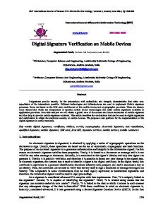
Figure 1: Our interactive system for verification of view-dependent elements performs SVBRDF capture using the built-in LED on the mobile device (top-left). The user gets an overview of relevant views for verification, which are color-coded w.r.t. the decision of the user (right, note the number attached to each view). The system allows the user to accurately match given referene views and to compare the changes of holographic or similar security elements with the corresponding reference appearances (bottom).
under different viewing directions and dominant light directions. These elements appear on various id cards, passports and most notably banknotes. Consequently, the task of checking such elements is of general interest. We investigate the feasibility of checking view-dependent elements with a mobile AR system using information from a real-time tracking system running on consumer hardware. Our system assists in efficient capture of these elements and presents the user with a comparison between the expected appearance of a view-dependent feature and the real observed one under the current viewing direction. In this context, we propose a novel approach for active alignment of a mobile device with a 3D reference pose using iron sights and a virtual horizon. The user can then decide whether to accept the element as genuine or reject. While a comparison from a single point of view can lead to rejection, acceptance requires to check all important viewing directions that present different appearances. Thus, our system also guides the user to the different directions and records the progress along the way (see Figure 1 and Section 4). We tested the feasibility of this approach in several steps. We evaluated under which conditions a mobile device can capture the different appearance of such an element (see Section 3.2). We also investigated if it is possible to move to the correct viewpoints using the proposed approach for visual guidance during a user study. Given pairs of reference and test images captured with a mobile device, we subsequently investigated patch similarity, but also user decisions on validity, and compared it to a digital manual based approach (see Section 5). We also discuss possibilities for automatic capture.
2
R ELATED W ORK
View-dependent elements such as optical variable ink and in particular holograms change their appearance depending on the viewing angle or the nature of light sources in the scene. Holography is based on recording and reconstruction of entire wavefronts (points having the same phase) as an interference pattern using a coherent light source (e.g., laser) [21]. Holograms can be characterized depending on the position of the photosensitive medium used for recording. Often so-called rainbow holograms are encountered, where the recording media was positioned off-axis and which can be viewed by using white light, letting the object appear in all spectral colors. Besides, there are also 3D variants such as the holographic stereogram, which displays a brief video sequence when being tilted. Holograms are often copied as a complete substitute but most counterfeit examples are of poor quality (e.g., printed on diffraction foil). Currently, the inspection of holograms is based on printed guides or digital manuals. Often being issued by public authorities, they usually show distinct patterns visible within the hologram area. However, they often lack an indication on the viewing direction and do not specify requirements on the lighting conditions. Consequently, the inspection may be tedious for the untrained user. In the absence of specific information, holograms tend to be inspected just by looking for changes in appearance or the pure presence of rainbow colors, which has no particular value with respect to security [21]. Holography has been the topic of several efforts in computer vision. Burage-Lefebvre et al. compute digital reconstructions of particle holograms based on the wavelet transform [4]. Janucki et al. use a Wiener filter to quantitatively assess the quality of holograms [13]. Then, there are automatic inspection systems for holograms with multiple patterns by Hyuk-Joong and Tae-Hyoung [14, 18]. They illuminate the document using multiple infrared LEDs positioned hemispherical above it. Images are captured with a CCD camera at controlled illumination angle and correlationbased matching is carried out in the frequency domain. They extend the system with correction of rotation angles and evaluate it with two Korean banknotes. In contrast to this work, our aim is to support hologram verification in a mobile context and to provide a more extensive evaluation. Besides verification, there have been efforts to combine holograms with computer graphics [2]. By extending a partial hologram reconstruction with additional content, a dynamic high-quality display can be realized [3]. Capturing holograms is largely related to capturing a spatially varying bidirectional reflectance distribution function (SVBRDF). This 6D function characterizes the amount of radiance that is reflected at each surface point when viewed from direction d and being lit from direction l. Ren et al. describe a portable solution to SVBRDF measurement of flat surfaces using a mobile device, a BRDF chart and a linear light source [20]. Being based on an approach by Dong et al. [7], they locally reconstruct purely specular components which allows for arbitrary per-point variation of diffuse and specular parts. However, in the context of verification, it is sufficient to have a means of comparison rather than capturing the entire representation. Jachnik et al. conduct real-time surface light-field capture from a single hand-held camera with fixed exposure, shutter and gain [12]. However, they require a static planar scene and illumination and split diffuse and specular components, finally estimating an environment map. Interestingly, they rely on a guidance component in the form of a colored hemisphere, which indicates whether a pixel has been seen from the particular viewing direction. Being designed for mobile verification, our proposed approach does not require capture of the entire representation, but only a few selected poses. To obtain these poses, a view navigation component is required.
AR-based view navigation for positioning (i.e., determining one’s location) in the outside area was conducted by Cheng at al. [5]. They use a coarse positioning system and manual matching of images with points of interest, finally computing the position of the user. However, we operate within much smaller workspaces and require more accurate positioning. Closely related work comes from the field of tele-manipulation [6]. Chintamani et al. use AR cues for navigation of the end effector in a surgical scenario. They display colored augmented coordinates to facilitate display-control alignment. However, we provide an interactive approach for alignment of an arbitrary six degree of freedom pose within in a mobile AR workspace providing guidance and instant feedback. 3 C APTURING VIEW- DEPENDENT ELEMENTS WITH MOBILES The view-dependent security elements show high-detail images that change drastically depending both on the viewing direction and the dominant light direction. Therefore, a single image cannot capture the full appearance of such elements. We chose to represent the elements using a SVBRDF representation (see Haindl and Filip [9] for a complete overview) that allows us to both preserve the dependence on viewing and lighting angles as well as the spatial variation of the images. Furthermore, we are only interested in planar, thin surfaces - printed documents - and therefore we do not require accurate models of self-shadowing or subsurface scattering effects. However, because we are targeting a handheld mobile application where the device and the document are both moving, we require a full BRDF representation as opposed to a surface light field as captured by Jachnik et al. [12]. Thus we are effectively using a 6D appearance model per color channel, where the radiance I is a function of both location (x, y) on the document, as well as incoming light direction l and viewing direction d: I = I(x, y, l, d).
(1)
The direction vectors l and d are unit length and therefore have only 2 degrees of freedom. In our application we are mainly interested in showing a representative image of the view-dependent element to the user. Therefore, we make several simplifying assumptions. We assume that the total radiance from a point on the element is dominated by a single major light source direction. Thus we do not integrate over all incoming light directions, but a single snapshot is enough given the dominant direction. Furthermore, we do not require a fully radiometric calibration and do not control for automatic exposure and white balancing in the camera. We simply sample the appearance as a set of images indexed by viewing direction d and light direction l. We do not attempt to estimate a smooth BRDF model covering all points on the element, but rather keep the individual images as the final representation. This preserves the sharp changes in appearance when the element flips from one view to another, as well as the necessary detail in the spatial domain. 3.1 Light source In practice, the dominant light direction poses a challenge in a mobile setup. Without any prior knowledge, we cannot reliably index into the list of appearance images. Therefore, we re-use the LED light source on a mobile as a constant source of illumination in the scene. As this is usually close to the camera, it easily dominates other light source in the environment. Because the LED is fixed with an offset vector o with respect to the camera, the light direction l is now a function of the camera pose with respect to the document (see Figure 2). The light direction is now proportional to the camera position P plus offset vector o rotated by the camera rotation in world coordinates. l ∝ P+R·o
(2)
Figure 2: With the LED light source in a fixed configuration to the camera, there are only 3 degrees of freedom in the input to the SVBRDF function.
For a fixed distance to the surface, P is just a rotated vector as well, and we obtain a similar equation for the viewing direction 0 d ∝ R · 0 (3) 1 Thus our representation is reduced to a 5D model, indexed by the full 3D camera rotation and the location (x, y) on the document. 3.2 Feasibility We performed an initial feasibility check w.r.t. image capture on the Samsung Galaxy (SIII) mobile phone using the built-in camera and flashlight. We captured various holograms on banknotes and plastic cards and observed whether the recorded appearance matches those illustrated in given reference material for the element under consideration. According to Figure 3, it is possible to capture different appearance states of view-dependent elements with this setup. When operated at a small distance to the document, the builtin LED flashlight dominates other light sources in typical indoor scenarios. This assumption is invalidated with strong artificial light sources or when operating outside (e.g., direct sunlight). In such cases, the workspace must be carefully shielded (e.g., manually). The flashlight may introduce severe specular highlights, even directly on the hologram. These highlights usually appear around the orthogonal view of the target, but do not affect the application much, because the more interesting views for verification are often at an angle away from the normal. Moreover, the verification of most holograms does not require dense sampling but relies on a rather limited number of specific views. The location of the LED close to the camera would indicate that the light direction l can be approximated with the viewing direction d. However, we tested this and we clearly observe a dependency
Figure 3: Captured view-dependent elements using the proposed setup.
Figure 4: Visualization of repeated capture while rotating around the optical axis (top left). Dependency of rotation around the optical axis on the appearance (images 1-7). The upper patches show element images captured by the camera. The lower patches show the unwarped element images that form the appearance model.
in the appearance on rotations of the device around the camera’s optical axis. Figure 4 shows an example. While the phone pointed along the same direction from the element, it was rotated around the optical axis, leading to different images. 4 P ROTOTYPE Following the insights gained from our feasibility study we constructed a mobile AR prototype for hologram verification. By visually tracking the known document (see Section 4.1), the system estimates the current viewing direction and camera pose. The camera rotation indexes into the stack of appearance images of a reference element. Then the reference image is brought up for comparison with an image captured from the live video frame. This approach does not need any further user input besides covering all possible viewing directions and orientations. However, there are usually only a fixed set of different appearances which are related to a set of main viewing directions. Therefore, the system has an active user guidance component that leads the user to compare specifically this set of main viewing directions (see 4.2). 4.1 Document recognition and tracking The first step required is the recognition of the unknown document to be verified. We adapted a mobile visual search pipeline for this task, running standalone on the mobile device. We compute SURF features [1], cluster them in a hierarchical k-means tree [17] and perform geometric verification by robust homography estimation to re-introduce spatial information. This provides reasonable recognition performance and scales up to a large number of documents. We then configure a natural feature tracker with a representative example of the recognized document class. Our natural feature tracking implementation runs in real-time directly on the mobile device similar to [22]. We initialize the tracker
by estimating a pose from matched BRISK [15] features extracted from a given template selected during visual search. Both detection and tracking rely on the assumption that we are observing planar objects. This is often violated with paper-documents, however. As in most cases this does not lead to tracking failure but pose jitter, we smooth out the poses in a ring buffer to improve stability. Averaging the pose over 2-3 frames stabilizes the view, while the introduced lag is small for this particular setup. 4.2
User guidance for verification
The system guides the user to capture a frame from the same viewing direction and under the same light direction as captured in the reference image set. Using the LED light of the mobile phone as a dominant light source, the task is simplified to aligning the current pose of the mobile phone operated by the user with several reference views having six degrees of freedom. 4.2.1
Conceptual Approach
We propose a visual guidance approach inspired by two widely known metaphors, namely iron sights and virtual horizon. Iron sights are used to align the viewing direction of the operator with the direction of the device. In general, shaped alignment markers are used for this task, which are positioned at a given distance on the device. Accounting for distance or scale depends on the task and requires a calibration procedure. This is often applied in sighting mechanisms. The virtual horizon is an indicator of level, which is often used when a device needs to be aligned relative to the ground. At any time the instrument shows the level of the object relative to earth gravity. Implementations range from a simple water level for mechanical tasks to advanced electronic devices used in aircrafts. Based on these techniques, we subdivide view alignment into three steps: We match the direction of the viewing ray (iron sights), the position along ray and also the in-plane rotation (virtual horizon). It is crucial to guide the user through these steps, so that accurate alignment can take place (see Figure 5 for a conceptual overview). 4.2.2
Implementation
We implemented the proposed guidance approach in an interactive prototype for mobile devices. The iron sights setup is realized by using two big circles which mark start- and end-point of the viewing ray. By using the intrinsic parameters of the camera, we scale the lower ray circle so that it overlaps entirely with the top circle once direction and distance match. For easier alignment, we additionally use a smaller ray base circle, which is intended to overlap with a small sphere fixed on the device screen. Their scale is also adapted with the intrinsic parameters. The virtual horizon setup consists of
Figure 5: Geometry of the proposed alignment approach. Matching the current view with a given reference view takes place by aligning the viewing ray direction, position (base sphere on the device screen with the ray base circle, ray top circle with the ray bottom circle) and orientation (virtual horizon on top of ray with the virtual horizon on the device screen).
Figure 6: Exemplary alignment sequence: Not aligned (top left). Aligning direction using iron sights (top right). Adjusting distance (bottom left). Aligning rotation using the virtual horizon (bottom right).
two lines placed at the top of the ray and two similar lines fixed on the screen. By using two different colors for each line, we account for a possible ambiguity in rotation around the optical axis (see Figure 6). We used the following color scheme to support the three-step alignment approach: red for on-screen sphere, small ray base circle, green for big ray base circle, top ray circle and blue/yellow for the virtual horizon. Depending on the most similar (w.r.t. orientation) reference pose, an automatic pre-selection is carried out by the system, drawing the full iron sights and virtual horizon setup for the selected reference pose only. Whenever the user makes a selection, the color of the reference ray is adapted. So the user gets a short summary of her decisions when viewing the setup from farther away and also knows where no decision was recorded up to that point. We also draw the last captured ray associated with the current reference pose so that the user can get an impression of how well the captured views fit (see Figure 1 and Figure 6). 4.3 SVBRDF capture The choice of reference poses obviously depends on the hologram (e.g., number of transitions) and is constrained by the particular setup being used. For each view, we require stable tracking and reproducible appearance. While the first mainly excludes low angles and extreme close-up views from being recorded (tracking failure), the latter limits the maximum viewing distance and avoids orthogonal angles which produce specular highlights due to the placement of the LED light. In practice, it seems reasonable to operate roughly at constant distance from the hologram, giving a hemispherical capture space. For the holograms described in this paper we recorded two to six views with stable appearance of the patches at a distance of approximately 10 cm. During verification, image capturing is triggered by the user when the alignment of a reference pose and the current pose is deemed close enough for accurate visual feedback. In this case, an auto-focus operation is triggered and the tracking pose is checked for stability before the current frame and corresponding pose are recorded. This is to avoid recording of pose jitter or blurry patches. We assume the hologram to be planar and project the bounding box of the hologram into the image by using the current pose. We then estimate an image transformation with respect to the hologram region on the undistorted template and subsequently warp the subimage containing the hologram. Consequently the appearance of the warped patch corresponds to the selected viewing direction.
This allows for an efficient comparison. We display this patch sideby-side with a reference patch. This similarity must be rated by the user to express consent, uncertainty or rejection. 5 E VALUATION To test the feasibility of the proposed approach for mobile hologram verification, we determined several performance parameters with users in a pilot study. This study had two aims: • Record the performance of users in target acquisition. • Provide a first comparison to a simple paper based method. For system performance, we wanted to know, how accurate users can acquire the necessary viewing directions, given our guidance systems. Understanding the potential accuracy limits is important for determining minimal angles and distances between views for verification and learning what differences the system has to tolerate. Moreover, we wanted to see, if users can correctly verify a hologram using the current system. It is not clear, if the representation on the screen under real lighting conditions is comparable and looks similar enough to users. An additional goal was to analyze the potential for automatization of the process, which includes automatic capture and matching of hologram patches. 5.1 Study Design and Apparatus We followed a controlled, within-subjects study design recording view alignment and matching performance, but also comparing the effects of the AR interface and a digital manual (DM, providing visual step-by-step instructions, see Figure 7) on several aspects in a hologram verification task. We investigated both performance based measures (alignment error, task completion time, error rates in matching and for the main task) and user experience (UX) dimensions (instrumental dimensions like usability, non-instrumental dimensions like hedonic stimulation and identity, and emotional dimensions like intrinsic motivation). The experiment took place under controlled laboratory conditions. Specifically, the lighting was fixed to allow for comparable results in the digital manual condition. Both interfaces were deployed on Samsung Galaxy (SIII) smartphones. The tasks were carried out while seated at a round table, but users were free to move around at any time (see Figure 8). 5.2 Task and Procedure As main task we chose the verification of the hologram present on a 50 Euro banknote, which is one of the most often counterfeited banknotes in the Euro zone [8]. It must be noted that the holograms on banknotes with higher values (100, 200, 500 Euro) behave in a very similar way. The participants should inspect four holograms with each interface. Specifically, they were asked to view the hologram
Figure 8: Image showing table setup used during the study (left). Specimen banknote with window showing hologram to be checked by participants of the study (right).
from six different viewpoints (depicting three different pictures: the banknote value, a window, and a doorway - see Figure 1 for view locations), but were free to stop the hologram verification before completing all views if they already came up with a decision. They were instructed to compare the reference close-up view of the hologram with the view of the hologram that they were inspecting and decide if they were similar. We pointed out that the holograms do not have to match on a pixel-by-pixel view but did not give any further hints on what similar meant, leaving this decision up to the participants. After inspecting the hologram from all six views, participants should come up with an overall decision if the hologram was a real one or a counterfeited one. We did not inform the participants at any time before, during or after the experiment if counterfeited (or real) holograms were among the ones they inspected. We used eight printed specimen notes in total (four per interface) and only left a hole for showing the underlying hologram of a real banknote (see Figure 8) to avoid that the checking of further security features of the banknote could influence the participants judgments. All employed holograms were real (no counterfeited hologram was used). At the beginning of the experiment, users filled in a background questionnaire. They proceeded with a learning phase of the starting interface (AR or digital manual, counterbalanced) inspecting a hologram not related to banknotes followed by the main task. After inspecting each banknote, participants briefly indicated their confidence in following aspects in an online questionnaire: Is the current hologram real or fake? Did the depicted reference viewpoints match the ones of the participants? Did the depicted reference close-up views match the ones the participants saw? After checking the holograms on all four banknotes, participants completed intermediate questionnaires regarding workload and UX qualities of the interaction. They then repeated the procedure (training, main task, questionnaires) with the second interface. At the end of the study, a short semi-structured interview was conducted, focusing on aspects observed during the participants’ interactions with the interfaces. The overall duration of the experiment was around 60 minutes. 5.3
Participants
We conducted the study with 17 volunteers (1 female). Most participants reported to have considerable experience with computers and a high interest in technical matters. Only two volunteers reported not to own a smartphone or tablet. However, the majority (13 participants) had never checked a hologram before. Three of the participants were English speaking but all instructions and questionnaires were given to the participants in either German or English. Figure 7: Exemplary view used in the digital manual. Overall image indicating the viewpoint (left). Zoomed image of the hologram patch (right).
5.4
Data collection
Within the experiment we collected device, video and survey data complemented with photos and notes. For the AR system, we
Results
We first analyze user performance in view navigation by comparison with the six given reference views at all relevant events. The subsequent analysis of patch similarity using image-based measures gives an impression on the performance of the proposed approach for mobile SVBRDF capture. Then, we provide results on tasklevel performance (hologram verification) for the AR system and the DM, which attributes to patch similarity rated by the user and the ability to come up with a final decision. Finally we provide results related to the user’s subjective assessment. One participant took significantly longer for the proposed tasks than was suggested. As this behavior was limited to a single person, we consider the associated runs to be outliers and do not use the associated data in the evaluation. Maneuvering to Target Poses
We analyzed data corresponding to all selected views during the study. Ranges of alignment errors in translation and rotation give a hint on the level of accuracy attainable with our guidance approach (see Figure 9). The range of translation error is -8mm to 10mm. The range of rotation error is -8 to 8 degrees. Overall, the largest error is encountered with view number 4. This was the first view typically selected by most of the participants, when they were still gaining familiarity with the system. ●
● ● ●
●
●
● ●
● ●
●
●
●
● ● ● ●
●
● ●
●
●
●
●
●
● ●
●
● ● ●
●
●
● ● ● ● ●
● ●
●
● ● ●
● ● ●
● ●
● ● ●
−0.1
●
●
● ●
●
●
●
●
●
●
●
● ●
0.8 NCC scores 0.4 0.6 0.2
●
● ● ●
●
V1 V2 V3 V4 V5 V6
●
−2
100
Figure 9: Alignment errors for different views of the hologram captured in the user study. Translation (left). Rotation (right). Axis colorcoded: x...red, y...green, z...blue
−1
200
V1 V2 V3 V4 V5 V6
0.0
●
● ●
●
●
−6
●
Regarding the task completion time, the medians of the AR and the DM interface were 188 and 103 seconds, respectively (see Figure 11, left). As the data was not normal distributed, a two-tailed Wilcoxon signed-rank test was employed and showed that there is a significant effect of interface (W = 1687, Z = 4.48, p < 0.05, r = 0.48) on task completion time. Participants rated how sure they were that the banknotes are real and fake for each banknote (see Figure 11, right). In addition, they rated how confident they were that the individual hologram views corresponded to the reference close up views and how confident they were that their viewpoints corresponded to the reference viewpoints (camera poses). For the pooled results (over all four banknotes), a two-tailed Wilcoxon signed-rank tests showed no significant effect of interface on any of those ratings.
●
● ●
● ●
Task Performance
● ● ● ●
●
●
● ● ●
● ● ●
5.5.2
● ● ●
●
●
●
to account for inaccuracies due to unstable tracking (see Figure 10). In this setup four out of the six views obtain average NCC scores above 0.75. This suggests that the proposed setup for SVBRDF capture allows acquisition of hologram patches for non-expert users despite varying lighting conditions and limits in pose accuracy. Two views have very low NCC scores, however. Again, one of them is the view most users approached first, when they cannot be considered entirely familiar with the system.
1
● ● ●
● ●
● ●
●
0
●
● ●
● ●
●
●
●
●
● ●
500
2
●
●
●
●
● ●
●
● ●
●
● ●
●
● ●
●
orientation error in deg −4 −2 0
positional error in cm 0.0 0.1 0.2
●
● ● ●
● ● ●
●
● ●
● ●
●
●
●
●
Figure 10: Matching registered patches: reference, warped image, registered image (left). NCC scores with registered images for different views (right).
400
5.5.1
●
V1 V2 V3 V4 V5 V6
seconds 300
5.5
●
2
recorded camera poses and user interactions and captured hologram patch data along with task completion time. In case of the digital manual (DM), we measured the task completion time with a separate clock. In addition, the actions of the users were videotaped. Besides quantitative analysis of data, we employed several subjective scales to capture both general UX dimensions as well as task-specific aspects. Specifically, we employed the Nasa TLX for workload assessment [10], AttrakDiff [11] for capturing hedonic (stimulation, identity) and pragmatic UX dimensions and the interest/enjoyment and value/usefulness sub-scales of the Intrinsic Motivation Inventory (IMI) [16]. We analyzed quantitative data with the R statistical package and Microsoft Excel. Null hypothesis significance testing (NHST) was carried out at the 0.05 level. For the positional and orientation data, we treated all data outside the 2.5% and 97.5% percentiles as outliers. The percentiles were computed on the aggregated data over all views.
Another way to assess the performance of users using the guidance system, is to compare the captured patches with a suitable image similarity metric. We register reference and captured patches using optical flow [19] and use normalized cross correlation (NCC) as our measure for patch similarity. The optical flow correction is
AR
DM
AR
DM
Figure 11: Task completion times for the augmented reality and digital manual interfaces (left) and agreement to ’I think the hologram is real’ (right).
● ● ●
●
0.5
20
●
1.0
●
●
1.5
● ●
25
30
●
●
MD AR DM PD AR DM TD AR DM Per AR DM
Eff AR
DM Fru AR DM
PQ AR
PQ DM
HQ−I AR
HQ−I DM
HQ−S AR
HQ−S DM
Figure 13: AttrakDiff scores for Pragmatic Quality (PQ), Hedonic Identity (HQ-I), and Hedonic Stimulation (HQ-S) on a 5-item bipolar scale.
1.5
Figure 12: Weighted NASA TLX dimensions for demands imposed on subject and for task interaction (MD: Mental Demand, PD: Physical Demand, TD: Temporal Demand, per: Performance, Eff: Effort, Fru: Frustration.
−1.5
0
5
10
−0.5 0.0
15
●
6
D ISCUSSION
The results obtained with the proposed approaches for SVBRDF capture and user navigation demonstrate that it is possible to record different appearances of hologram patches with consumer hard-
Quality PQ HQ-I HQ-S
AR M SD -.08 .37 .42 .37 .6 .39
DM M SD .28 .37 -.15 .60 -.54 .67
t(13) -2.58 3.20 7.58
p .02 .005 6e-7
Cohens’s d .37 .78 1.92
Table 1: Group differences for UX Qualities PQ, HQ-I and HQ-S between the AR and DM interface condition.
0.0
We used the NASA TLX weighted scores scheme to assess subjective demands. For computation of the scores we used both the magnitude of load (ratings) and sources of load (weights), which evaluate the contribution of each factor. The ratings for demands on subject and for task interaction are shown in Figure 12. Twotailed Wilcoxon signed-rank tests indicated a significant effect of interface (W = 98, Z = 2.13, p < 0.05, r = 0.37) on physical demand (MD for AR: 14.67, MD for DM: 3.33) and a significant effect of interface (W = 111, Z = 2.32, p < 0.05, r = 0.40) on temporal demand (MD for AR: 5.67, MD for DM: 4.00). There were no significant differences in NASA TLX weighted scores for the other dimensions. The AttrakDiff questionnaire is an instrument for measuring the attractiveness of an interactive system along pragmatic and hedonic user experience qualities. Paired two-tailed t-tests were conducted to compare the effects of the interfaces on the pragmatic quality (PQ), hedonic quality identity (HQ-I), and hedonic quality stimulation (HQ-S). Each subscale consists of seven items with a bipolar rating scale. We used five item scales and averaged the ratings of all seven items for each subscale. Group differences for UX qualities PQ, HQ-I and HQ-S between the AR and DM interface condition are reported in Table 1 and Figure 13. The interface had a significant effect on all dimensions, with the AR interface leading to a significant lower score for the pragmatic (usability) dimension (with a medium effect size), but significantly higher scores for the hedonic dimensions (with large effect sizes). We also assessed the participant’s intrinsic motivation through the IMI [16]. Specifically, we employed the interest/enjoyment and value/usefulness subscales (5-point Likert scale). A two-tailed Wilcoxon signed-rank test indicated significant effect for AR (MD : 0.86) and DM (MD : −0.29) on Interest/Enjoyment (W = 123, p < .05, r = .38). There was no effect on value/usefulness (see also Figure 14).
0.5
1.0
Subjective Assessment
●
−1.0
5.5.3
● ● ●
IE AR
IE DM
Figure 14: IMI scores Value/Usefulness (VU).
VU AR
for
VU DM
Interest/Enjoyment
(IE)
and
ware. More specifically users were able to reach the six views used in the study with reasonable accuracy (maximum range of translation error from -8 to 10 mm, maximum range of rotation error from -8 to 8 degrees; see Figure 9). It must be noted that the used specimen banknote did not remain entirely planar during the study. Although potentially leading to larger errors, real banknotes often suffer from similar deformations. Consequently several users commented that final alignment was tedious and should be automated. This could be achieved by capturing several frames and selection of a reasonable trade-off between stability and alignment accuracy. Patch similarity computed after registration gave NCC scores greater than 0.75 for four of the six views (see Figure 10). While the pixel-wise registration improved NCC scores noticeably, the obtained pose accuracy was close enough to the reference view that the appearance of the view-dependent elements was correct. Thus, while we need to automatically correct for small pose variances, the correct sector for the view-dependent appearance was usually selected. On the task level, the AR system shows similar verification performance compared with a digital manual, but longer task completion times (see Figure 11) and higher physical and temporal demand (see Figure 12). This is reasonable, because users are forced to move to the right pose, which ensures repeatable conditions and reasonable matching of patches. However, none of the evaluated interfaces was able to provide clear evidence whether a hologram is real or not (see Figure 11). While the AR system was also not rated better in terms of usability (pragmatic quality), both the AttraktDiff (see Figure 13) and IMI (see Figure 14) questionnaires indicated significant higher ratings for hedonic dimensions and interest/enjoyment. This could indicate a higher motivational value for non-professional end users to employ the AR system for hologram verification. While most users requested automatic capture and patch matching, some users also suggested a summary page or the possibility
release the user from cognitive strain. It seams reasonable to automatically trigger all image capture operations and also perform matching of patch data. Such measures could finally pave the way for a fully automatic verification system residing in your pocket. ACKNOWLEDGEMENTS This work is supported by Bundesdruckerei GmbH. Figure 15: Improved user interface (left): Top-left patch showing reference data for the nearest reference view, top-right patch showing captured data by the user. Bottom-left patch showing live view of the warped hologram patch. Additional elements represent visual ranges for easier alignment. Automatic recapture (right): The hologram is recaptured when a more suitable pose is encountered.
to have a live view of the warped hologram patch. We redesigned the user interface to address these issues and to support a more natural workflow for verification. We incorporated a real-time view of the warped patch and added automatic recapture of the hologram, whenever a better match concerning pose is encountered (see Figure 15). We also provide cues for each of the steps required during alignment in the form of additional graphical elements representing alignment ranges. Finally, we show the reference patch and the best recorded patch concerning pose for the nearest reference frame. The user can now continuously inspect the hologram, get instant visual feedback and modify local decisions on validity. We conducted an informal study with seven of the original participants, comparing the updated user interface with the previous iteration. Five of seven users felt more confident (two equal) on their decision concerning validity. However, six of seven users rated temporal effort to be equal (one less). Users verbally reported that they found the live-view and the alignment ranges to be useful. Regarding cognitive and physical strain, five of seven users rated the system to be equal to the previous iteration (two less straining). Not being able to work with actual fakes in the study certainly limits insights concerning practical usability. However, credible fake documents and in particular holograms are difficult to produce or acquire. The challenge is to get hold of samples which are not immediately identified as fake but strongly resemble genuine items. This also means that simple photocopies are of limited value. However, the approach could be evaluated with holograms from different documents embedded in a generic looking surround or even with rotated or possibly thermally treated holograms. The latter would allow to gain more insights w.r.t. practical usability. 7 C ONCLUSION We investigated the feasibility of capturing and checking viewdependent elements using off-the-shelf mobile devices. To this end, we capture a patch-based SVBRDF representation with a mobile device using a dominant light source in fixed location relative to the mobile’s camera. Then users can verify a view-dependent element through comparing the captured live image with the stored SVBRDF representation. In order to simplify the process, we proposed a novel guidance approach based on iron sights and the virtual horizon. This allows the user to efficiently match the pose of the phone with pre-recorded views of the hologram. We implemented this approach in a mobile interactive AR system performing document recognition and tracking and supporting hologram verification. We then conducted a user study comparing a digital manual with the AR system showing encouraging results for the performance of the AR system. The obtained results prove that it is feasible to capture and verify holograms in a manual setting on off-the-shelf mobile phones. However, further investigation is required to obtain more robust tracking also for flexible paper documents. We need to minimize errors in translation and rotation when matching views and further
R EFERENCES [1] H. Bay, A. Ess, T. Tuytelaars, and L. V. Gool. Speeded-up robust features (surf). CVIU, 110(3):346–359, 2008. [2] O. Bimber. Combining optical holograms with interactive computer graphics. IEEE Computer, 37(1):85–91, 2004. [3] O. Bimber, T. Zeidler, A. Grundhoefer, G. Wetzstein, M. Moehring, S. Knoedel, and U. Hahne. Interacting with augmented holograms. In SPIE Practical Holography XIX: Materials and Applications, volume 5742, pages 41–54, 2005. [4] C. Burage-Lefebvre, S. Cotmellec, D. Lebrun, and C. zkul. Application of wavelet transform to hologram analysis: three-dimensional location of particles. OptLE, 33(6):409–421, 2000. [5] Y.-C. Cheng, J.-Y. Lin, C.-W. Yi, Y.-C. Tseng, L.-C. Kuo, Y.-J. Yeh, and C.-W. Lin. Ar-based positioning for mobile devices. In ICPPW, pages 63–70, 2011. [6] K. Chintamani, A. Cao, R. Ellis, and A. Pandya. Improved telemanipulator navigation during display-control misalignments using augmented reality cues. Systems, Man and Cybernetics, Part A: Systems and Humans, 40(1):29–39, 2010. [7] Y. Dong, J. Wang, X. Tong, J. Snyder, Y. Lan, M. Ben-Ezra, and B. Guo. Manifold bootstrapping for svbrdf capture. In ACM SIGGRAPH 2010 papers, pages 98:1–98:10, 2010. [8] E.C.B. Biannual inform. on euro banknote counterfeiting, Jan. 2013. [9] M. Haindl and J. Filip. Visual Texture. Advances in Computer Vision and Pattern Recognition. Springer Verlag, 2013. [10] S. G. Hart and L. E. Staveland. Human Mental Workload, chapter Development of NASA-TLX (Task Load Index): Results of empirical and theoretical research. North Holland Press, Amsterdam, 1988. [11] M. Hassenzahl, M. Burmester, and F. Koller. AttrakDiff: Ein Fragebogen zur Messung wahrgenommener hedonischer und pragmatischer Qualit¨at. In Mensch & Computer 2003: Interaktion in Bewegung, pages 187–196, Stuttgart, Germany, 2003. B. G. Teubner. [12] J. Jachnik, R. A. Newcombe, and A. J. Davison. Real-time surface light-field capture for augmentation of planar specular surfaces. In ISMAR, pages 91–97, 2012. [13] J. Janucki and J. Owsik. A wiener filter based correlation method intended to evaluate effectiveness of holographic security devices. Optics Communications, 218(4-6):221–228, 2003. [14] H.-J. Kwon and T.-H. Park. An automatic inspection system for hologram with multiple patterns. In SICE, pages 2663–2666, 2007. [15] S. Leutenegger, M. Chli, and S. R. Brisk: Binary robust invariant scalable keypoints. In ICCV, pages 2548–2555, 2011. [16] E. McAuley, T. Duncan, and V. V. Tammen. Psychometric properties of the intrinsic motivation inventory in a competitive sport setting: A confirmatory factor analysis. Research quarterly for exercise and sport, 60(1):48–58, 1989. [17] D. Nister and H. Stewenius. Scalable recognition with a vocabulary tree. In CVPR, pages 2161–2168, 2006. [18] T.-H. Park and H.-J. Kwon. Vision inspection system for holograms with mixed patterns. In CASE, pages 563–567, 2010. [19] T. Pock, M. Urschler, C. Zach, R. Beichel, and H. Bischof. A duality based algorithm for tv-l1-optical-flow image registration. In MICCAI, pages 511–518, 2007. [20] P. Ren, J. Wang, J. Snyder, X. Tong, and B. Guo. Pocket reflectometry. In Proc. SIGGRAPH 2011, SIGGRAPH ’11, pages 45:1–45:10, New York, NY, USA, 2011. ACM. [21] R. L. van Renesse. Optical Document Security. Artech House, third edition, 2005. [22] D. Wagner, G. Reitmayr, A. Mulloni, T. Drummond, and D. Schmalstieg. Real-time detection and tracking for augmented reality on mobile phones. TVCG, 16(3):355–368, 2010.