Mitigating starvation in Wireless Ad hoc Networks: Multi-channel MAC and Power Control Duc Ngoc Minh Dang
Phuong Luu Vo
Chi Kwang Hwang
Department of Computer Engineering Kyung Hee University, Korea
Department of Computer Engineering Kyung Hee University, Korea
Department of Computer Engineering Kyung Hee University, Korea
[email protected]
[email protected] Choong Seon Hong
[email protected]
Department of Computer Engineering Kyung Hee University, Korea
[email protected] ABSTRACT
1.
The IEEE 802.11 DCF (Distributed Coordination Function) is based on CSMA/CA (Carrier Sense Multiple Access with Collision Avoidance). However, the CSMA-based random access protocol can cause serious unfairness or flow starvation. In this paper, we propose a multi-channel MAC with the power control (STPC-MMAC) to mitigate the starvation by exploiting the multiple channels and improving the spatial reuse of wireless channel. The main idea of our proposal is to use the IEEE 802.11 Power Saving Mechanism (PSM) with different transmission power levels used in the Announcement Traffic Indication Message (ATIM) window and the data window. All nodes transmit the ATIM messages with the maximum power while negotiating for the data channel in the ATIM window, and use the minimum required transmission power for their data transmissions in the data window on the negotiated channels. The simulation results show that the proposed STPC-MMAC can improve the network performance: aggregate throughput, average delay, energy efficiency and especially fairness index.
In a dense network, nodes may suffer from intensive contention from their neighbors. As a result, some flows may be starved and refrained from transmissions for a prolonged period of time. There are many proposals to improve the performance of the wireless ad hoc network. One approach is to use the appropriate power control mechanism [3,7,12,13]. In [7], a node is allowed to periodically increase the transmission power during data transmission in order to inform nodes in the carrier sensing range of its transmission. An Adaptive Range-based Power Control (ARPC) MAC protocol [13] is proposed to avoid POINT problem which is defined in [12]. The SINR-based Transmission Power Control for MAC protocol (STPC-MAC) in which the receiving SINR is guaranteed at the receiver is proposed in [3]. The transmission power information is exchanged during the ATIM window. Neighbor nodes estimate the transmission power with which they can transmit simultaneously. During the data window, they can transmit the data packets without collision. Besides the transmission power control approach, some proposals tune the carrier sensing threshold [17, 18] to improve the spatial reuse. The spatial backoff algorithm [17] is proposed to adjust the space occupied by each transmission by tuning carrier sensing threshold, power and transmission rate. Based on the required SINR, Zhu et al. propose a dynamic algorithm that adjusts the carrier sensing threshold to maximize the spatial reuse in [18]. Another approach is to employ the multi-channel MAC to exploit the multiple channels. There are four approaches for the multi-channel MAC protocol as classified in [8]: Dedicated Control Channel, Split Phase, Common Hopping and Parallel Rendezvous. In the Dynamic Channel Assignment (DCA) [16], each node has two radios: one radio is tuned to the channel dedicated to control packets while another can switch to any other channels for data transmission. The Dynamic Channel Assignment with Power Control (DCAPC) [15] is an improvement of DCA. In the DCA-PC, all control packets RTS/CTS/RES are transmitted using the maximum power on the control channel, while DATA/ACK packets are transmitted with the minimum required power on the data channel. Time is divided into alternating sequence of
Categories and Subject Descriptors C.2.2 [Computer-Communication Network]: Network Protocols
General Terms Algorithms
Keywords Power Control, Multi-channel, MAC protocol, Ad hoc networks.
Permission to make digital or hard copies of all or part of this work for personal or classroom use is granted without fee provided that copies are not made or distributed for profit or commercial advantage and that copies bear this notice and the full citation on the first page. To copy otherwise, to republish, to post on servers or to redistribute to lists, requires prior specific permission and/or a fee. IMCOM (ICUIMC)’14, January 9-11, 2014, Siem Reap, Cambodia. Copyright 2014 ACM 978-1-4503-2644-5 ...$15.00.
INTRODUCTION
Carrier Sensing Range S1
R3
S4
R4
R5
R2
S2R2 BO
RTS
RTS
BO
BO
BO: Back off (a) Hidden node starvation
S5
S7
R7
S6 S5R5
S4R4 RTS
R6
R1 S2
S1R1
S3
S6R6 S7R7
S3R3 (b) Asymmetric sense starvation
(c) Carrier sense starvation
Figure 1: Starvation scenarios in CSMA-based wireless ad hoc networks. control interval or contention interval and data transmission interval in the Multi-channel MAC (MMAC) [14]. During the control interval, all nodes have to switch to control channel and try to reserve data channels for their data transmissions. In the data interval, they switch to the agreed data channel to exchange data packets. In [4], a power control scheme STPC-MAC [3] is applied to MMAC protocol to improve the network performance. A hybrid multichannel MAC protocol (H-MMAC) [2], an enhancement of the MMAC, allows some nodes to exchange data packets during the ATIM window. This protocol utilizes all the channel resources during the ATIM. In this paper, we propose STPC-MMAC by applying a power control algorithm to the multi-channel MAC protocol. The STPC-MMAC can solve the starvation problem by exploiting the multiple channels and using the transmission power control. The contributions of this paper with respect to the existing publications can be summarized as follows: the ATIM window is divided into N sub-slots which represent N channels. So, nodes are not required to use the ”best” channel selection algorithm to select a data channel, nodes only have to exchange the ATIM messages in one sub-slot to reserve the corresponding data channel. A modified Neighbor Information List (NIL) is used to simplify the algorithm used to update the status of the neighbor nodes. We also define the control frames format to show that our proposal requires little changes in the ATIM frames compared to the current standard in order to apply it in real environment. The rest of this paper is organized as follows. Section 2 reviews the starvation in CSMA-based wireless ad hoc networks. In section 3, our proposed protocol is described in details. Section 4 presents simulation results. Finally, we conclude this paper in section 5.
2. STARVATION IN CSMA-BASED WIRELESS AD HOC NETWORKS There are three well-known sources of starvation [5] such as hidden node starvation, asymmetric sense starvation and carrier sense starvation as shown in Fig. 1. The dashed circles indicate the carrier sensing range of the centered node. • Hidden node starvation arises when a sender is outside the carrier sensing range of another sender, but its receiver is within the carrier sensing range of another sender. In Fig. 1(a), sender S2 knows exactly when
the channel is available based on the control messages sent by node R1 . Although node R1 receives the RTS successfully, it cannot reply CTS to node S1 because it is within the carrier sensing range of node S2 . Therefore, if two flows S1 R1 and S2 R2 are backlogged, flow S2 R2 has higher throughput than flow S1 R1 . • Asymmetric Sense starvation arises when nodes have different transmission power levels, carrier sensing thresholds or channel conditions. In Fig. 1(b), node S3 can sense the transmission of node S4 , but node S4 cannot sense the transmission of node S3 . Therefore, node S4 always find the channel to be idle when it has data packets to send, while node S3 has to freeze its back-off counter and defer its transmission when it senses the transmission of node S4 . • Carrier Sense starvation arises when the sender senses the transmission of its neighboring nodes that are not within the carrier sensing range of each other as shown in Fig. 1(c). Node S5 and S7 cannot sense each other, but node S6 can sense both node S5 and S7 . If all flows are backlogged, flow S6 R6 is locked by flow S5 S5 and/or S7 S7 . It results in the low throughput in flow S6 R6 and high throughput in flows S5 R5 and S7 R7 . The above starvation is the long-term starvation in the dense wireless ad hoc networks. The starvation would be eliminated if all transmissions occurred on orthogonal channels or all nodes controlled their transmission power. The appropriate power control algorithm and multi-channel MAC protocol give us some benefits such as: starvation avoidance, improved spatial reuse, fairness, low energy consumption, high throughput. Our proposed protocol adopts the IEEE 802.11 PSM [1]. During the ATIM window, nodes contend to exchange the ATIM messages for the data channel negotiation. After that, nodes switch to the agreed data channel for data transmissions. The details of the STPC-MMAC protocol are described in the following sections.
3.
THE PROPOSED STPC-MMAC PROTOCOL
There are three non-overlapping channels in IEEE 802.11b and g, and twelve non-overlapping channels in IEEE 802.11a.
I2
I1
D
B
RN ) d (P
) d (P
T
R
C
T
RN
S
A
S
R
I6
S
R
G
I3 E
I5
F
H
I
I4
(a) Node R sends ATIM-ACK (b) Node S sends ATIM-RES (c) 6 first tier interfering nodes (worst case) (d) STPC-MMAC example Figure 2: The interference model. We assume that there are N non-overlapping channels which can be used. Each node has a single half-duplex transceiver which can either transmit or listen but cannot do both simultaneously. All nodes are time synchronized. The clock synchronization can be achieved by using GPS or the IEEE 802.11 TFS (Timing Synchronization Mechanism) [1]. In addition, several clock synchronization protocols have been proposed in [9, 11]. The synchronization overhead is small and the maximum clock offset can be achieved as 15µs [9]. Time is divided into beacon intervals which are the alternating sequences of the ATIM window and the data window (Fig. 5). The ATIM window is further divided into N sub-slots which represent N channels. One channel is defined as a default channel (CH1) during the ATIM window. Nodes have to be on the default channel to exchange the ATIM/ATIM-ACK/ATIM-RES messages (ATIM messages) for negotiating the transmission power level Pd and the transmission mode. The ATIM messages are sent on the chth sub-slot to select the chth data channel. Moreover, all the ATIM messages are transmitted with the maximum power Pmax . After the ATIM window, nodes switch to their selected channel ch to exchange data packets at the minimum required transmission power Pd indicated in ATIM messages. Now, we describe our proposed protocol in detail.
3.1 The power control In this section, we present how the node estimates its transmission power Pd used in the data window and how the neighbor nodes update their transmission power limit in order to control their interference to the others. First, we define the terms transmission range and noise threshold range. • Transmission Range (RT R ): the range within which a packet can be successfully received and correctly decoded. This range can be estimated based on the receiving power threshold PRXthold and the receiving SINR threshold SIN Rthold . • Noise Threshold Range (RN T ): the range within which node receives the interference level greater than the noise power threshold PN thold . The noise threshold range is larger than transmission range. Without loss of generality, let PtS be the transmission power of sender S, PrS be the receiving power from sender S at receiver R. And by using the two-ray ground reflection model [10], the receiving power PrS is calculated from the
following formula: PrS (R) = PtS Gt Gr
PS h2t h2r = c tα , α d L d
(1)
where Gt , Gr are antenna gains of transmitter and receiver; ht , hr are the heights of the transmit and receive antennas; d is distance between transmitter and receiver; L is other losses, assume L = 1 here then c is constant; α id path-loss coefficient with range of 2-4. The receiving power depends on path-loss over the distance d between sender and receiver. Here, we ignore other minor factors such as multipath fading, shadowing, environmental noise, etc. And the Signal to Interference plus Noise Ratio (SINR) of the node R is given as SIN R(R) =
PrS (R) Signal ∑ = , Interf erence σ0 + Pri (R)
(2)
i=1,i̸=S
where Pri (R) is the interference caused by the interfering node i, and the thermal noise σ0 is neglected. Since other interfering nodes are far away and contribute a smaller interference than the first tier interfering nodes, we ignore them in SINR calculation. The packet is successfully received and correctly decoded when PrS (R) ≥ PRXthold and SIN R(R) ≥ SIN Rthold . In our protocol, nodes must be outside the noise threshold range RN T of each other except their intended senders or receivers in order to perform the data transmission simultaneously. In Fig. 2(a), after receiving the ATIM message from node S, node R replies with the ATIM-ACK message indicating the transmission power Pd . Upon receiving the ATIM-ACK, node S confirms the transmission power level Pd by sending the ATIM-RES(Pd ). Neighboring nodes which have overheard the ATIM-ACK/ATIM-RES messages know whether they are outside the noise threshold range of node R or not. Only nodes outside the noise threshold range may transmit data packets simultaneously with nodes S and R. In Fig. 2(b), after the ATIM messages are exchanged, nodes S and R give a warning to all neighbor nodes which are within their noise threshold ranges. The maximum interference in the worst case is achieved when the interfering nodes also have the same noise threshold range with nodes S and R. The maximum total interference is given when node S is very close to node R as shown in Fig. 2(c) T otal Int = 6 · PN thold .
(3)
Given PRXthold and SIN Rthold , we have to find the value of PN thold by using the total interference in Eq. 3 and above two conditions of receiving packet correctly; PN thold =
PRXthold . 6 · SIN Rthold
(4)
When node R receives the ATIM message from node S with the receiving power PrPmax , it has to estimate the minimum required transmission power Pd that node S has to use to transmit data packets by: Pd =
Pmax · PRXthold . PrPmax
(5)
If a neighbor node (for example, node I3 in Fig. 3) is in the region between the RT R (Pmax ) and RN T (Pmax ), the maximum transmission power that can be used to transmit data packets is Pdmax =
PN thold · Pmax Pmax = . PRXthold 6 · SIN Rthold
(6)
RNT(Pmax) RNT(Pd)
S R
J
0 Pd Pdmax Pmax I1 I2 I3 I4
S
R
0 0 0 Pmax I5 I6 I7 I8
RTR(Pd) RTR(Pmax)
(b) RNT(Pd) < RTR(Pmax) (ATIM/ATIM-ACK/ATIM-RES)
(c) RNT(Pd) > RTR(Pmax) (ATIM/LATIM-ACK/LATIM-RES)
Figure 3: Two scenarios for updating transmission power limit. Fig. 3 illustrates two scenarios used to update transmission power limit Plim , the maximum transmission power a node can transmit: RN T (Pd ) < RT R (Pmax ) and RN T (Pd ) < RT R (Pmax ). The nodes which are within the transmission range of Pmax can decode the ATIM messages to know Pd . And then, they can distinguish which scenario is used to update Plim . For the nodes which are within the range (RT R (Pmax ), RN T (Pmax )), they have to monitor how long the sensing power Psense is larger than PN thold . We use the ATIM-ACK/ATIM-RES in the case of RN T (Pd ) < RT R (Pmax ) (Fig. 3(a)) and the longer LATIM-ACK/LATIM-RES for the another case RN T (Pd ) < RT R (Pmax )(Fig. 3(b)). Fig. 4 shows the timing of ATIM messages exchange. Since node S may not send ATIM-RES, the neighbor nodes set NAV(ATIM) until node S begins sending ATIM-RES. Nodes R and S use LATIM-ACK/LATIM-RES to warn the nodes which are in the range (RT R (Pmax ), RN T (Pmax )) with the
Figure 4: Timing of ATIM messages exchange.
ch Algorithm 1 Algorithm to update Plim in each beacon ch 1: Plim ← Pmax /*At the start of each beacon*/ 2: repeat 3: if Receives (L)ATIM-ACK/(L)ATIM-RES(Pd ) correctly during the sub-slot of data channel ch then N thold 4: if Pr ≥ Pmax .P then Pd ch 5: Plim ← 0 /*Node I1 , I5 in Fig. 3*/ 6: else ch ch 7: Plim ← min(Plim , Pd ) /*Node I2 in Fig. 3*/ 8: end if 9: else if Psense ≥ PN thold for duration > TAT IM −ACK then ch 10: Plim ← 0 /*Node I6 , I7 in Fig. 3*/ 11: else if Psense ≥ PN thold for duration = TAT IM −ACK then ch ch 12: Plim ← min(Plim , Pdmax ) /*Node I3 in Fig. 3*/ 13: end if ch =0 14: until ATIM window ends or Plim
estimated transmission power Pd > (Pmax .PN thold )/PRXthold . Although the durations of the LATIM-ACK/LATIM-RES are longer than those of the ATIM-ACK/ATIM-RES, they have the condition to guarantee the LATIM-ACK reception at the sender S. The condition for the length of LATIMACK/LATIM-RES can be described as TLAT IM −ACK < TAT IM −ACK + SIF S + DIF S.
(7)
During the ATIM window, a node determines the sub-slot of the data channel ch and updates the transmission power ch limit Plim of the channel ch, based on the received power Pr of the overheard ATIM messages or the sensed power Psense ch by Algorithm 1. This Plim value is stored in TPL (Section 3.2) for the corresponding channel. Next, we apply the power control mechanism to the multichannel MAC protocol to improve the network performance. We define two transmission modes (Tx mode) • Normal Transmission (N-Tx): the transmission performed within the data window. • Extended Transmission (E-Tx): the transmission performed within the data window and the next ATIM window. In Fig. 5, nodes A and B perform the N-Tx mode while nodes G and H perform the E-Tx mode. If a node uses the NTx mode, it will be on the default channel in the next ATIM window. But a node will be on the default channel in the next two ATIM windows if it uses the E-Tx mode. Nodes G and H are on the default channel in the third ATIM window because they use the E-Tx from the first beacon. However, it is not necessary to use the E-Tx mode in the low network load because of long delay. If the node utilizes one more ATIM window, it will waste a longer data window. In the high network load, the node needs to use the E-Tx to get more time to transmit data packets to increase the network throughput. That means a node needs to detect the network load in order to choose the transmission mode. In the high network load, many nodes try to contend the channel, and the collision probability is high. When the collision happens, the retry counter increases. Nodes can use the retry counter as a factor to select the transmission mode. In addition, the
Channel#2
DATA(C-D) DATA(E-F)
DATA(C-D)
DATA(A-B) Channel#3 DATA(G-H) ATIM(Sender-Receiver): Exchanging ATIM/ATIM-ACK/ATIM-RES between Sender and Receiver
ATIM(H-I)
ATIM(E-F) ATIM(A-B)
Beacon#4
DATA(C-D) DATA(A-B)
ATIM(G-C)
ATIM(I-H)
Channel#1
ATIM(E-F)
Beacon#3
DATA(E-F)
ATIM(C-D) ATIM(A-B)
ATIM(A-B)
ATIM(C-D)
Beacon#2
DATA(A-B)
CH#1CH#2CH#3 ATIM(E-F)
ATIM(C-D) ATIM(E-F) ATIM(G-H)
Beacon#1
Data_Win
ATIM(A-B)
ATIM_Win
DATA(G-C)
DATA(I-H)
DATA(E-F) DATA(A-B)
DATA(E-F)
DATA(H-I)
Time DATA(Sender-Receiver): Exchanging DATA/ACK between Sender and Receiver
Figure 5: The operation of STPC-MMAC protocol (Topology is given in Fig. 2(d)). packet arrival rate at each node is another factor in making decision for the transmission mode selection. If there are many active nodes in the network and many data packets to send, the node will choose the E-Tx mode.
3.2 Neighbor Information List and Transmission Power List Each node maintains its data structures, which are called the Neighbor Information List (NIL) and the Transmission Power List (TPL). The NIL stores the information about the neighbor nodes such as: channel, Next ATIM and transmission mode, while the TPL stores the transmission power limit Plim of each channel.
3.2.1 Neighbor Information List - NIL Each list entry keeps the information about the neighbor nodes including channel, Next ATIM and Tx mode. Channel 0 means that is an idle node. Next ATIM means when the corresponding node is on the default channel. For example, nodes G and H are going to use the E-TX mode in the first beacon. They will be on the default channel after two beacons. Table 1 shows the NIL of node A at the end of the first ATIM window.
Node C G E H ...
Table 1: Node A’s NIL Channel-CHNL Next ATIM Tx mode 2 1 N-Tx 3 2 E-Tx 2 1 N-Tx 3 2 E-Tx ... ... ...
Algorithm 2 Update node A’s NIL in each ATIM window 1: /*At the beginning of ATIM window*/ 2: Next ATIM ← Next ATIM - 1 for all neighbors in NIL 3: if Node A is on the data channel then 4: if Next ATIM == 0 then 5: Next ATIM ← 2 /*E-Tx assumption*/ 6: end if 7: else 8: Updates NIL whenever overhears the ATIM messages 9: end if
data channel, it will miss all control messages exchanged in the current ATIM window. So, it assumes that all nodes that are on the control channel will use the E-Tx mode and it updates the zero Next ATIM to 2 in its NIL. Otherwise, the node which is on the control channel updates its NIL whenever it overhears the ATIM messages from its neighbors by Algorithm 2 during the ATIM window.
3.2.2
Table 2: Node A’s TPL Channel - CH Tx Power Limit - Plim CH1 50 CH2 250 CH3 100 During the sub-slot ch, the receiver uses the values Plim of both sender and receiver for the data channel ch to verify if they can use that data channel ch at the estimated transmission power Pd .
3.3
Control frames
In the IEEE 802.11 PSM, we use the ATIM and ACK messages to do handshake between two nodes. For our proposed protocol, both the sender and receiver have to exchange ATIM/(L)ATIM-ACK/(L)ATIM-RES messages on the default channel to negotiate the data channel, transmission power and transmission mode for their data transmissions. This three-way handshake also serves the purpose of informing the neighbor nodes of the sender and receiver. We modify the ATIM frame format and define two ATIMACK/ATIM-RES frames as shown in Fig. 6. We use 1 byte to represent the transmission power (256 levels). The Tx mode field specifies which transmission mode is used.
3.4 A node needs to know the current status of its neighbor node before exchanging the ATIM messages. At the beginning of each ATIM window, each node decreases the nonzero Next ATIM value by 1 in its NIL. If a node is on the
Transmission Power List - TPL
Each node maintains the data structure call Transmission Power List (TPL). In TPL, each entry stores the power limit Plim for each channel as shown in Table 2. This value limits the maximum transmission power of each node in the current beacon. At the beginning of each beacon, all Plim are set to Pmax . All nodes have to listen to the default channel during the ATIM window, and update the Plim for the corresponding data channel by Algorithm 1 according to the overheard ATIM messages or the sensing power.
The operation of STPC-MMAC protocol
The operation of the proposed STPC-MMAC protocol is illustrated in Fig. 5 with the topology in Fig. 2(d). Now, we assume that sender node S has data packets for receiver node R at the sub-slot corresponding to the channel ch. We
Bytes: 2
2
Frame Duration Control
ATIM
Bytes: 2
2
6
6
Receiver Address
Transmitter Address
6
Frame Duration (L)ATIM-ACK Control
Receiver Address
Bytes: 2
6
(L)ATIM-RES
2
Frame Duration Control
Receiver Address
1
6 BSS ID
1
Tx Power Tx level Mode 1
1
1
Tx Power Tx level Mode
1
4
Tx Power Tx FCS level Mode
4 FCS
LATIM-ACK
4 FCS
LATIM-RES
Figure 6: The control frame format. describe the procedure used in STPC-MMAC protocol as the following 1. Node S checks the status of node R in its NIL. If node R is available on the default channel (Next ATIM = 0), during the chth , node S sends the ATIM including the transmission mode T x and the transmission power limit Plim of the corresponding data channel ch to node R at the maximum power Pmax . Otherwise, it has to wait for the next sub-slot and try again. 2. Based on the receiving power PrPmax of the ATIM message, node R estimates the required transmission power Pd for the data transmission (Eq. 5). Based on the Pd and both Plim of nodes S and R, node R checks if the data channel ch is available for their data transmissions. If that data channel is available, node R sends the (L)ATIM-ACK(T x, Pd ) to node S. Otherwise, node R sends the ATIM-ACK(N U LL, N U LL) to indicate that they cannot exchange data on this channel. 3. If node S receives the (L)ATIM-ACK(T x, Pd ), it confirms the transmission mode T x and the transmission power Pd by replying the (L)ATIM-RES(T x, Pd ); otherwise it does not send anything.
Nodes E and F found that they can use the data channel 2 simultaneously, and they also exchange ATIM messages to reserve the data channel 2. In the third sub-slot, nodes G and H exchange ATIM messages to reserve the data channel 3. Moreover, they decided to use E-Tx mode because of network traffic load. Node I, the neighbor node of node H, overhears the ATIM messages from node H and knows that node H will be available on the default channel after 2 ATIM windows. If node I has data packets for node H, it can start from the third ATIM window as shown in Fig. 5. In the STPC-MMAC, nodes have to exchange the ATIM messages which indicate the transmission power Pd and the transmission mode T x during the ATIM window. Since a node pair exchanges the ATIM messages once during the ATIM window, after that other nodes have chances to send the ATIM messages. That means there is no long-term starvation during the ATIM window. Another reason why the STPC-MMAC can mitigate the starvation is the SINR-based transmission power mechanism. This mechanism helps the STPC-MMAC provide more concurrent transmissions during the data window compared to the MMAC and H-MMAC protocols. For example, in Fig. 1 each flow can use different channels to transmit data packets simultaneously. Flows S1 R1 and S2 R2 may also use the same channel with the minimum required transmission power.
4. Based on the overheard ATIM messages, the neighbor nodes update their NILs (Algorithm 2) and TPLs (Algorithm 1).
4.
5. After the ATIM window, both sender S and receiver R switch to the selected data channel ch and exchange the RTS/CTS followed by the multiple DATA/ACK packets. The other nodes that did not exchange the ATIM messages successfully go to doze mode to save energy.
4.1
Let us consider the network topology example in Fig 2(d). The dash line is the transmission range when the nodes exchange data packets during the data window. In the first beacon of Fig. 5, nodes A and B exchange the ATIM messages to reserve the data channel 1 for their data transmissions. In the second sub-lot, nodes C and E have data packets to send to nodes D and F, respectively. However, node C accesses the default channel successfully and exchanges ATIM messages with node D to reserve the data channel 2.
PERFORMANCE EVALUATION
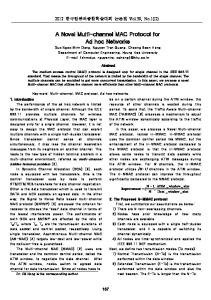
In this section, we have evaluated IEEE 802.11 [1], MMAC [14], DCA-PC [15] and our proposed STPC-MMAC protocol by our developed packet-level simulation tool in Matlab.
Simulation Model
The network consists of 50 nodes placed randomly in a 500m x 500m area. Each node selects the neighboring node in its transmission range to form a transmitter-receiver pair. Source node generates and transmits constant-bit-rate (CBR) traffic to its destination. The other major simulation parameters in our simulations are listed in Table 3. Each simulation was performed for 5 seconds and the simulation results are the average of 40 runs. In the simulation, we use the following metrics to evaluate the TCP performance of different protocols: the aggregate throughput, average delay, Jain’s fairness index [6] and the energy efficiency which is defined as the average power consumption per data packet.
(a) Aggregate throughput, 50 nodes
(b) Average delay, 50 nodes
(c) Fairness index, 50 nodes
250
(d) Energy efficiency, 50 nodes
1
100
20 0.9 200
16 14 12 10 8
0.8 Jain’s fainress index
Average delay (msec)
Aggregate throughput (Mbps)
18
150
100
0.7
0.6
0.5
6
2 0
200 400 600 800 Packet arrival rate per flow (packets/sec)
IEEE 802.11 MMAC DCA PC STPC MMAC
50
IEEE 802.11 MMAC DCA PC STPC MMAC
4
0
IEEE 802.11 MMAC DCA PC STPC MMAC
0
1000
0
200 400 600 800 Packet arrival rate per flow (packets/sec)
0.4
1000
0
200 400 600 800 Packet arrival rate per flow (packets/sec)
1000
Energy consumption per data packet (mJ/packet)
22
IEEE 802.11 MMAC DCA PC STPC MMAC
90 80 70 60 50 40 30 20 10 0
200 400 600 800 Packet arrival rate per flow (packets/sec)
1000
Figure 7: Performance comparison of different protocols.
Table 3: Simulation’s Parameters Parameters Value Number of channels 3 channels Beacon Interval 100 ms ATIM window 10 ms SIFS 16 µs DIFS 34 µs Slot time 9 µs ATIM 28 bytes ATIM-ACK 16 bytes ATIM-RES 16 bytes LATIM-ACK 20 bytes LATIM-RES 20 bytes Basic rate 1 Mbps Data rate 2 Mbps Data packet size 512 bytes Retry limit 4 Path loss coefficient 4 Maximum radio power 250 mW PRXthold -82 dBm PN thold -95.78 dBm SIN Rthold (dB) 6 Transmit power consumption 1.65 W Receive power consumption 1.4 W Idle power consumption 1.15 W Doze power consumption 0.045 W
4.2 Simulation Results Fig. 7 shows the performance comparisons of different protocols versus the packet arrival rate. The aggregate throughput and average delay of different protocols are shown in Fig. 7(a) and (b), respectively. By exploiting multiple channels, the aggregate throughput of the multi-channel MAC protocols are higher than IEEE 802.11 MAC protocol designed for a single channel. And the average delays of multi-channel MAC protocols are lower than that of the IEEE 802.11. However, the DCA-PC uses one channel for control packets and 2 data channels for data transmissions while there is 10% overhead of the ATIM window in the MMAC. Different from the MMAC, the STPC-MMAC allows nodes to exchange data packets during the ATIM window. In addition, more concurrent transmissions are achieved by the power control algorithm. That is why when the network load is high, the STPC-MMAC has higher aggregate throughput and lower delay than the MMAC and DCA-PC.
In the IEEE 802.11, if nodes always exchange data packets, other nodes may not have chance to access the channel due to the starvation problems. But during the ATIM window, after nodes exchanged ATIM messages successfully, other nodes have chances to exchange their ATIM messages in both the MMAC and STPC-MMAC. After the ATIM window, nodes switch to the agreed channel for their data transmissions. By exploiting multiple channels and using power control, the STPC-MMAC offers more concurrent transmissions. As a result, the STPC-MMAC has higher fairness index compared to others as shown in Fig. 7(c). The energy efficiency is also one benefit of the proposed the STPC-MMAC protocol as shown in Fig. 7(d). Although the transmitting nodes adjust their transmitting power in the DCA-PC protocol, the idle nodes stay awake and consume the idle power of 1.15 W. Moreover, the DCA-PC also consumes more power because each node is equipped with 2 transceivers. Both the MMAC and STPC-MMAC adopt the PSM which allows nodes to enter doze mode with a doze power consumption of 0.045 W when there is no need for data exchange. Having the higher throughput and less energy consumption, the STPC-MMAC protocol has better energy consumption per data packet than the others.
5.
CONCLUSION
In this paper, we propose the new MAC protocol (STPCMMAC) by combining the power control algorithm and multichannel MAC protocol. The STPC-MMAC can exploit the multiple channels as well as increase the spatial reuse to mitigate the starvation in wireless ad hoc network. Simulation results showed that the STPC-MMAC protocol improves the aggregate throughput, the average delay, the energy efficiency and especially the fairness among nodes in the network.
6.
ACKNOWLEDGMENT
This research was supported by Next-Generation Information Computing Development Program through the National Research Foundation of Korea(NRF) funded by the Ministry of Science, ICT & Future Planning (2010-0020728). Dr. CS Hong is the corresponding author.
7.
REFERENCES
[1] Wireless lan medium access control (mac) and physical layer (phy) specification. IEEE 802.11 Working Group, 1997.
[2] D. N. M. Dang and C. S. Hong. H-mmac: A hybrid multi-channel mac protocol for wireless ad hoc networks. In Communications (ICC), 2012 IEEE International Conference on, pages 6489–6493, June 2012. [3] D. N. M. Dang, C. S. Hong, S. Lee, and J. Lee. A sinr-based mac protocol for wireless ad hoc networks. Communications Letters, IEEE, 16(12):2016–2019, December 2012. [4] D. N. M. Dang, M. V. Nguyen, C. S. Hong, S. Lee, and K. Chung. An energy efficient multi-channel mac protocol for wireless ad hoc networks. In Global Communications Conference (GLOBECOM), 2012 IEEE, pages 433–438, December 2012. [5] C. Hua and R. Zheng. Starvation modeling and identification in dense 802.11 wireless community networks. In INFOCOM 2008. The 27th Conference on Computer Communications. IEEE, pages 1696–1704, April 2008. [6] R. Jain, D.-M. Chiu, and W. R. Hawe. A quantitative measure of fairness and discrimination for resource allocation in shared computer system. Eastern Research Laboratory, Digital Equipment Corporation, 1984. [7] E.-S. Jung and N. H. Vaidya. A power control mac protocol for ad hoc networks. Wireless Networks, 11(1-2):55–66, January 2005. [8] J. Mo, H.-S. So, and J. Walrand. Comparison of multichannel mac protocols. Mobile Computing, IEEE Transactions on, 7(1):50–65, January 2008. [9] L. Qi and W. Chen. A clock synchronization method for ad hoc networks. In Artificial Intelligence, Management Science and Electronic Commerce (AIMSEC), 2011 2nd International Conference on, pages 3614–3617, August 2011. [10] T. S. Rappaport et al. Wireless communications: principles and practice, volume 2. Prentice Hall PTR New Jersey, 1996. [11] C. Rentel and T. Kunz. A mutual network synchronization method for wireless ad hoc and sensor
[12]
[13]
[14]
[15]
[16]
[17]
[18]
networks. Mobile Computing, IEEE Transactions on, 7(5):633–646, May 2008. K.-P. Shih and Y.-D. Chen. Capc: A collision avoidance power control mac protocol for wireless ad hoc networks. Communications Letters, IEEE, 9(9):859–861, September 2005. K.-P. Shih, Y.-D. Chen, and C.-C. Chang. A physical/virtual carrier-sense-based power control mac protocol for collision avoidance in wireless ad hoc networks. Parallel and Distributed Systems, IEEE Transactions on, 22(2):193–207, February 2011. J. So and N. H. Vaidya. Multi-channel mac for ad hoc networks: handling multi-channel hidden terminals using a single transceiver. In Proceedings of the 5th ACM international symposium on Mobile ad hoc networking and computing, MobiHoc ’04, pages 222–233, May 2004. Y.-C. Tseng, S.-L. Wu, C.-Y. Lin, and J.-P. Sheu. A multi-channel mac protocol with power control for multi-hop mobile ad hoc networks. In Distributed Computing Systems Workshop, 2001 International Conference on, pages 419–424, April 2001. S.-L. Wu, C.-Y. Lin, Y.-C. Tseng, and J.-P. Sheu. A new multi-channel mac protocol with on-demand channel assignment for multi-hop mobile ad hoc networks. In Parallel Architectures, Algorithms and Networks, 2000. I-SPAN 2000. Proceedings. International Symposium on, pages 232–237, December 2000. X. Yang and N. Vaidya. A spatial backoff algorithm using the joint control of carrier sense threshold and transmission rate. In Sensor, Mesh and Ad Hoc Communications and Networks, 2007. SECON’07. 4th Annual IEEE Communications Society Conference on, pages 501–511. IEEE, June 2007. J. Zhu, X. Guo, L. Yang, and W. Conner. Leveraging spatial reuse in 802.11 mesh networks with enhanced physical carrier sensing. In Communications, 2004 IEEE International Conference on, volume 7, pages 4004–4011 Vol.7, June 2004.