Engineer On a Disk Overview: This note set is part of a larger collection of materials available at http://claymore.engineer.gvsu.edu. You are welcome to use the material under the license provided at http://claymore.engineer.gvsu.edu/eod/global/copyrght.html. As always any feedback you can provide will be welcomed.
Copyright © 1993-2001, Hugh Jack email:
[email protected] phone: (616) 771-6755 fax: (616) 336-7215
Copyright © 1993-2001, Hugh Jack
page 2
1. TABLE OF CONTENTS TABLE OF CONTENTS.......................................................................................................... 2 MATERIAL PROPERTIES ..................................................................................................... 4 TERMINOLOGY - - - - - - - - - - - - - - - - - - - - - - - - - - - - - - - - - - - - - - - - - - - - - 4 MICROSTRUCTURES - - - - - - - - - - - - - - - - - - - - - - - - - - - - - - - - - - - - - - - - - 4 IRONS AND STEELS - - - - - - - - - - - - - - - - - - - - - - - - - - - - - - - - - - - - - - - - - - 8 NONFERROUS METALS AND ALLOYS - - - - - - - - - - - - - - - - - - - - - - - - - - - 15 HEAT TREATING - - - - - - - - - - - - - - - - - - - - - - - - - - - - - - - - - - - - - - - - - - - 16 PAUL JOHNSON NOTES FOR EGR 250 - - - - - - - - - - - - - - - - - - - - - - - - - - - 16 PRACTICE PROBLEMS - - - - - - - - - - - - - - - - - - - - - - - - - - - - - - - - - - - - - - - 43
page 3
Materials Information
page 4
2. MATERIAL PROPERTIES • Ideally materials are a microscopic matrix of small balls that form a larger solid. In reality the atoms that make of solids fall into local pockets of well organized matrices. It is very rare to find a solid that is made up of a single structure. • If solids were made of single well organized molecules they would be significantly stronger. But, small deformations and cracks weaken materials to the values we are more accustomed to. • Material properties are a function of multiple factors. Primarily chemistry determines what atoms are available to make up the structure. Also, the atoms are dispersed in a non-homogenous mix. • Solids typically fail because cracks form, and then quickly propagate through solids. It is the chemistry and non-homogenous structure that can slow or stop these cracks. The composition of the solid also determines how stiff it is.
2.1 TERMINOLOGY • A basic list of terms commonly used are, Brittleness - the tendency of a material to break before it undergoes plastic deformation Ductility - the ability of certain materials to be plastically deformed without fracture (pulling). Elasticity - The ability to deform and return to the undeformed shape. This follows Hooke’s law. Hardness - the resistance to deformation and forced penetration Malleability - the ability of a material to take a new shape when hammered or rolled. Tensile Strength - the maximum tensile load that can be applied before a material fractures Toughness - The ability to withstand cracking, as opposed to brittleness Yield Strength - The load at which the material stops elastically deforming, and starts permanently deforming.
2.2 MICROSTRUCTURES • To consider materials properly we must start with the basic atomic structure and then look at the more macroscopic aspects, and how they are related to the microscopic components.
page 5
2.2.1 Atomic Structures • In an atom there are some fundamental ratios, • Each atom is understood to have a basic structure with a nucleus and orbiting electrons. • The nucleus is a combination of neutrons and protons. • The number of protons and neutrons in an atom are equivalent and these determine the atomic number. If there are additional neutrons in the nucleus this is called an isotope. • The mass of the atom is determined by the sum of the neutrons and protons (the electron mass is much smaller). • In a mole of material there are 6.023*10**23 atoms. • How these components fit together is described in models, Bohr model - electrons have quantized energy levels - electrons are discrete and orbit the nucleus - a free electron has a negative energy level Wave-mechanic model - electron waves can behave like particles or waves - an electron is described as an electron cloud - electrons have energy levels including ground levels - valence electrons are the outermost and most likely to be removed first • The valences of electrons are determined with the ’spdf’ numbers. • The basic atomic elements are listed in the periodic table. This is in sequence of the atomic masses, as well as proton counts. It can also be used to determine similarities in properties by proximity in the table.
page 6
1 H 1 .0080
2 He 4.00 26
3 Li 6.939
4 Be 9.01 22
5 B 1 0.811
6 C 12.0 11
7 N 1 4.007
8 O 15.9 99
9 F 1 8.998
10 Ne 20.1 83
11 Na 2 2.990
12 Mg 24.3 12
13 Al 2 6.982
14 Si 28.0 86
15 P 3 0.974
16 S 32.0 64
17 Cl 3 5.453
18 Ar 39.9 48
19 K 3 9.102
20 Ca 40.08
21 Sc 4 4.956
22 Ti 47.90
23 V 5 0.942
24 Cr 51.9 96
25 Mn 5 4.938
26 Fe 55.8 47
27 Co 5 8.933
28 Ni 58.7 1
39 Cu 6 3.54
30 Zn 63.3 7
31 Ga 6 9.72
32 Ge 72.5 9
33 As 7 4.922
34 Se 78.9 6
35 Br 7 9.91
36 Kr 83.8 0
37 Rb 85 .47
38 Sr 87.62
39 Y 88 .91
40 Zr 91.22
41 Nb 9 2..91
42 Mo 95.9 4
43 Tc (9 9)
44 Ru 101.07
45 Rh 1 02.91
46 Pd 106.4
47 Ag 1 07.87
48 Cd 112 .40
49 In 114.82
50 Sn 118 .69
51 Sb 1 21.75
52 Te 127 .60
53 I 1 29.90
54 Xe 131 .30
55 Cs 1 32.91
56 Ba 137.34
rare earth series
72 Hf 178.49
73 Ta 1 80.95
74 W 183.85
75 Re 1 86.2
76 Os 190.2
77 Ir 1 92.2
78 Pt 195.09
79 Au 1 96.97
80 Hg 200.59
81 Tl 2 04.37
82 Pb 207 .19
83 Bi 2 08.98
84 Po (210 )
85 At (2 10)
86 Rn (222 )
87 Fr (2 23)
88 Ra (226)
actinid e series
57 Rare Earth Series La 138.91
58 Ce 140.12
59 Pr 140.91
60 Nd 144.24
61 Pm (145)
62 Sm 150.35
63 Eu 151.96
64 Gd 157.25
65 Tb 158.92
66 Dy 162.50
67 Ho 164.92
68 Er 167.26
69 Tm 168.93
70 Yb 173.04
71 Lu 174.97
89 Ac (227)
90 Th 232.04
91 Pa (231)
92 U 238.03
93 Np (237)
94 Pu (242)
95 Am (243)
96 Cm (247)
97 Bk (247)
98 Cf (249)
99 Es (254)
100 Fm (253)
101 Md (256)
102 No (254)
103 Lw (257)
Actinide Series
• In the periodic table the metals are in the left hand side. They have 1 to 3 valence electrons. They tend to give up electrons when bonding. • In the upper right hand of the periodic table are the non-metals. They typically are 1 to 3 valence electrons short of a full valence level. As a result they tend to consume electrons when bonding. These are, He, N, O, F, Ne, P, S, Cl, Ar, Br, Kr, I, Xe, At, Rn • There is a band of semimetals - including semiconductors. These often consume and give up electrons when bonding. These are B, O, Si, Ge, As, Se, Te.
2.2.1.1 - Crystal Structures • Understanding crystal structures can help understanding of crystalline materials such as metals. • Think of dropping balls into a box. it can fall randomly, but often it will fall into patterns. This is like atoms in a solid. • If all of the balls fall into a single organized pattern then we can say there is a single crystal.
page 7
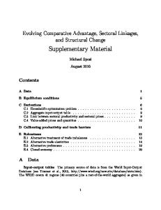
• Three of the basic structure types to consider are, bcc - body centered cubic fcc - face centered cubic hcp - hexagonal close packed
bcc
fcc
hcp
• In a common solid there will be many regions in the crystal, but there will also be boundaries where the crystal properties change. These are known as boundaries. • A common effect that can occur is slippage along one of the planes of the crystal. An example is pictured below,
A shear force results in slippage along the slip plane.
• Different crystal structures will result in different possible slip planes. bcc has 48 possible slip planes fcc has 12 possible hcp has 3 possible • Other slip structures are also possible
page 8
2.3 IRONS AND STEELS • Irons and steels are the most popular metals in use today. The production of iron was at one time a subject of mystic awe. • Any engineer involved with modern engineering should have at least a passing knowledge of steels to understand many of the processes.
2.3.1 Types of Steel • Various steel alloys are commonly identified with the SAE-AISI numbers,
page 9
Steel Alloy Type
Number
Description
Carbon
10xx 11xx 13xx 23xx 25xx 31xx 33xx 303xx 40xx 41xx 43xx 47xx 86xx 87xx 93xx 98xx 46xx 48xx 50xx 51xx 51xxx 52xxx 514xx 61xx 92xx xxBxx xxLxx
plain 0.05-0.90% carbon steels free cutting carbon steels 1.75% Mn 3.50% Ni 5.00% Ni 1.25% Ni and 0.65% Cr 3.50% Ni and 1.57% Cr Corrosion and heat resisting 0.25% Mo, carbon-molybdenum 0.95% Cr, chromium-molybdenum 1.82% Ni, 0.50% Cr, 0.25% Mo 1.05% Ni, 0.45% Cr, 0.20% Mo 0.55% Ni, 0.50% Cr, 0.20% Mo 0.55% Ni, 0.50% Cr, 0.25% Mo 3.25% Ni, 1.20% Cr, 0.12% Mo 1.00% Ni, 0.80% Cr, 0.25% Mo 1.57% Ni, 0.20 Mo 3.50% Ni, 0.25% Mo 0.27-0.50% Cr, low chromium 0.80-1.05% Cr, low chromium 1.02% Cr, medium chromium 1.45% Cr, high chromium corrosion and heat resisting 0.95% Cr, 0.15% V 0.65-0.87% Mn, 0.85-2.00% Si
Manganese Nickel Steels Nickel-chromium
Molybdenum Nickel-chromium-moldb.
Nickel-molybdenum Chromium
Chromium-vanadium Silicon-manganese Boron Leaded
• Typical applications for plain steels (based on the SAE-AISI numbers) are,
page 10
Number Properties
Applications
1006-12 soft and plastic Sheets, stripping, tubes, welding Low Carbon 1015-22 soft and tough rivets, screws, wire, structural shapes 1023-32 medium pipes, gears, shafts, bars, structural shapes 1035-40 Medium 1041-50 Carbon 1052-55
large section parts: forged parts, shafts, axles, rods, gears heat treated parts: shafts, axles, gears, spring wire heavy duty machine parts: gears, forgings
1060-70 shock resistant High 1074-80 tough and hard dies, rails, set screws Carbon 1084-95 shear blades, hammers, wrenches, chisels, cable wire cutting tools: dies, milling cutters, drills, taps, etc.
2.3.1.1 - Alloying Elements • A Short list of elements is given below,
page 11
Element
Effect
Boron Calcium Carbon Cerium Chromium Cobalt Copper Lead Magnesium Manganese Molybdenum Nickel Niobium Phosphorous Selenium Silicon Sulfur Tantalum Tellurium Titanium
hardenability, slight improvement of machinability and formability deoxidant, toughens, slight improvement of machinability and forming hardenability, strength, hardness, wear resistance, lower ductility, weldability, toughness controls inclusions, toughens, deoxidant toughens, hardenability, wear and corrosion resist, high temp. strength, aid carburization high temperature strength and hardness strengthens, resist air corrosion, reduces high temp. workability and surface quality embrittles, machinability like cerium hardenability, strength, abrasion resist, machinability, deoxidant, lower weldability hardenability, wear resist, toughness, high temp. strength, creep resist, hardness strengthens, toughness, corrosion resist, hardenability fine grains, strengthens, toughness, lower transition temp., lower hardenability strengthens, hardenability, corrosion resist, machinability, lower ductility
• Typical elements that are left over from the manufacturing processes leave behind detrimental elements, - antimony - arsenic - hydrogen - nitrogen - oxygen - tin
2.3.2 Making Steels • The basic process is, 1. Iron ore is mined, and crushed. At this point in contains iron, carbon, oxygen, and a variety of other minerals. 2. The ore is heated in a blast furnace with coke. This removes some of the elements, notably oxygen. Pig iron remains, and has high levels of carbon. 3. A refining furnace is then used to burn off the excess carbon, leaving a good quality
page 12
steel.
2.3.2.1 - The Ores • The ores come in a number of forms, - taconite -hermatite - iron oxide mineral - limonite - iron oxide and water • The ores are crushed to ease handling, and speed melting. • After crushing, iron rich ore can be separated using magnets. • the resulting ore is formed into pellets of about 65% iron.
2.3.2.2 - Coke • The classic recipe for Coke begins with bituminous coal. It is then heated to 2100°F and then cooled with water. • Coke will - generate higher level of heat during steel making - generate carbon monoxide which reacts with oxygen in iron oxide and leaves iron
2.3.2.3 - Flux, Slag • Some materials are used as a flux, and to create slag, - limestone - dolomite • By adding a flux material, it will react with impurities, causing them to flow. • After the flux dissolves the impurities, it reacts with them to form a solid called slag. This floats to the top of the melt, where it is removed.
2.3.3 The Blast Furnace - How To Make Pig Iron
page 13
• These furnaces are large heated vessels, and they are lined with bricks of refractory materials. • Iron pellets, limestone, and coke are mixed together and dumped into the top of the furnace. • Air is preheated to 2000°F and this is used to ‘blast’ the mixture into the furnace. The coke ignites, and elevates the temperature of the mixture to 3000°F. This results in a reduction of the iron oxides, and separation of the slags. • After some period of time (a few hours) the furnace is tapped, and the iron is drawn off to large ladles. This ‘pig’ iron typically has a impurity contents of 4% C, 1.5% Si, 1% Mn, 0.04% S, 0.4% P.
2.3.4 How To Make Steel • Making steel is a process of reducing the following impurities in pig iron, - manganese - silicon - carbon - phosphorous - sulphur - etc • This operation is commonly done in one of three furnaces, - open hearth - flames are directly applied to the metal, and can be seen from the open hearth. - electric - basic oxygen - a blast of pure oxygen reacts with impurities • The basic procedures with all of these furnaces is, 1. Charge (pour in) scrap iron 2. Pour in molten (pig) iron 3. Add lime 4. Run the furnace 5. Tap the furnace to remove the steel - care must be used not to pour the slag on the surface 6. Pour off the slag off • Any oxygen left in the steel when solidified will combined with carbon. The result is small voids that are actually pockets of carbon monoxide gas. A killed steel will have all oxygen removed.
page 14
2.3.4.1 - Electric Furnaces • There are two basic types, - induction - arcing • In induction furnaces large coils are wound around the crucible. AC current is applied, and this induces heat in the metal inside. Vacuum can be applied to the melt to increase purities of the final steel. • Arcing furnaces use carbon electrodes at high potentials to create arcs. These act to heat the metal. • The furnaces reach temperatures up to 3500°F.
2.3.5 Forming The Steel • There are options after the steel has been processed, - ingots - the steel is poured into ingots, and stored to be formed later - continuous casting - the steel is poured, and immediately formed to bars, rolls, etc. • Continuous casting uses a slow pour that when running smoothly, 1. Is liquid at the top where it is being poured. 2. It solidifies, still at forming temperatures, and typically moving at 5 fpm. A pulling action keeps a continuous rate. 3. It is rolled, bent, formed, and cut. • The result of continuous casting is a single process that produces final steel sections without any of the intermediate problems that result from remelting ingots.
2.3.6 Stainless Steel • These steels use a high Chromium content(10 to 12%) to form a protective layer of chromium oxide over the surface of the work that is resistant to many forms of corrosion • General families of stainless steels include, Austenitic (2xx, 3xx) Ferritic (4xx) Martensitic (4xx and 5xx) Precipitation Hardened (PH) -
page 15
Duplex •
2.4 NONFERROUS METALS AND ALLOYS
2.4.1 Aluminum
2.4.2 Titanium • silver colored • close packed hexagonal structure (alpha phase) • above 885°C the material undergoes beta phase transition to body centered cubic arrangements • four commercial grades ASTM 1-4
Grade
Properties UTS (ksi) YS (ksi) Elong.
Chemistry N (%) C (%)
H (%)
Fe (%)
O2 (%)
1 2 3
35 50 65
0.03 0.03 0.05
0.015 0.015 0.015
0.20 0.30 0.30
0.18 0.25 0.35
25 40 55
• melts at 1800°C • resistance to corrosion • twice steels strength to density • high affinity for carbon
24 % 20 % 18 %
0.10 0.10 0.10
page 16
• soft and ductile when annealed
2.5 HEAT TREATING
2.6 PAUL JOHNSON NOTES FOR EGR 250 • These notes in this section were copied from Paul Johnson’s web site and placed here.
2.6.1 Atomic Bonding and Structure
2.6.1.1 - Atomic Structure A.Fundamental Concepts 1.Atomic number - # of protons in nucleus 2.Atomic mass - sum of protons and neutrons 3.Atomic weight - weighted average of atomic masses of natural isotopes 4.Atomic mass unit (amu) - 1/12th the mass of 12C 5.Mole - Avogadro's Number (6.023 x 10²³) units (atoms or molecules) of a substance B.Atomic Models 1.Bohr model a.Quantized energy levels for electrons in atom b.Discrete (particle like) electrons in an orbital c.Energy levels are negative with respect to zero energy for a free electron 2.Wave-Mechanical model a.Wave is neither wave nor particle, but can act like either in certain situations b.Electron described as an electron 'cloud' c.Energy levels divided into subshells with discrete states for each pair of electrons given by quantum numbers 1.Principal quantum number n = 1, 2, 3, 4, 5, 6, 7 2.2nd quantum number, subshell, l = s, p, d, f 3.3rd quantum number, energy states in subshell, mi = 1(s), 3(p), 5(d), 7(f) 4.4th quantum number, spin moment, ms = +½, -½ d.Ground state - all electrons in atom filling lowest energy level states e.Valence electrons - electrons in highest energy shell in ground state
page 17
2.6.1.2 - Periodic Table A.Metallic elements 1.1 to 3 valence electrons 2.Electropositive - tend to give up electrons in bonding B.Non-metals 1.1 to 3 electrons short of full valence level 2.Electronegative - tend to add electrons in bonding C.Intermediate elements 1.Metallic and non-metallic characteristics 2.Includes semiconductors 3.May gain or lose electrons in bonding III.Atomic Bonding A.Bonding Reactions 1.Bonding forces a.Attractive force due to bond b.Repulsive force due to electron clouds c.Equilibrium when net force is zero 2.Bonding Energy - Equilibrium when energy is minimum B.Primary (Strong) Bonding 1.Ionic a.Transfer of electrons from electropositive to electronegative atoms b.Coulombic attraction between ions 2.Covalent a.Sharing of electrons between 2 (or a few) atoms b.Number of bonds are those needed to fill valence level c.Bonds between atoms with similar electronegativities 3.Metallic a.Sharing of electrons among many atoms b.Valence electrons 'free' to move c.Weak (Secondary) Bonding 4.Induced Dipole a.Temporary, short term shifts in charge creating dipoles b.Coulombic attraction between dipoles 5.Polar Molecules a.Permanent dipoles b.Large differences in attraction for electrons c.Coulombic attraction between dipoles 6.Hydrogen Bonding a.Special case of polar molecule bonding b.Dipoles formed between Hydrogen and highly electronegative atoms (e.g. H2O)
2.6.2 Ideal Crystal Structure
page 18
I.Crystal Structure Fundamentals A.Crystal structure – atoms arranged in regular, repeating pattern over large distances compared to atomic size B.Solid sphere model of atoms C.Lattice – 3-dimensional array of points arranged in a regular, repeating periodic structure D.Unit cell – the smallest portion of a lattice which represents the symmetry and structure of the entire lattice E.Equivalent sites – points in a lattice which are indistinguishable from other points in the lattice – in a real crystal each equivalent site is associated with an identical atom or group of atoms F.Lattice geometry 1.Crystallographic axes – x, y, z 2.Crystallographic angles – a, b , g 3.Unit cell dimensions a.in +x direction b.in +y direction c. in +z direction II.Crystal Systems and Structures A.Cubic Crystal System 1.a = b = c, a = b = g = 90° 2.Simple Cubic (SC) a.1 equivalent site per unit cell b.no crystals with only 1 atom per equivalent site 3.Face-Centered Cubic (FCC) lattice a.4 equivalent sites per unit cell b.common metals with 1 atom per equivalent site include – Al, Cu, Ni 4.Body-Centered Cubic (BCC) lattice a.2 equivalent sites per unit cell b.common metals with 1 atom per equivalent site include – Fe, Cr, W B.Hexagonal Crystal System 1.a = b ¹ c, a = b = 90° , g = 120° 2.1 equivalent site per unit cell 3.Face-Centered Hexagonal (FCC) a.2 atoms per equivalent site with close packed arrangement b.common metals with HCP structure include – Zn, Mg, Ti C.Tetragonal Crystal System a = b ¹ c, a = b = g = 90° D.Orthorhombic Crystal System a ¹ b ¹ c, a = b = g = 90° E.Rhombohedral Crystal System a = b = c, a = b = g ¹ 90° F.Monoclinic Crystal System a ¹ b ¹ c, a = g = 90° ¹ b G.Triclinic Crystal System a ¹ b ¹ c, a ¹ b ¹ g ¹ 90° III.Crystal Geometry
page 19
A.Points in a crystal 1.Set origin for crystal system 2.Points identified by translation from the origin B.Direction vectors 1.Move origin to tail of vector or draw parallel vector from origin 2.Determine translation to tip point 3.May also use tip minus tail to find translation 4.Convert indices obtained to lowest integer form 5.Place indices into brackets in form [uvw] 6.Negative indices indicated by a bar over the number C.Plane indices 1.Find intercepts of plane with the three crystallographic axes 2.If plane includes the origin, move either the plane or the origin 3.Invert intercept values obtained 4.Convert reciprocals to lowest integer form 5.Place indices in parentheses in form (hkl) 6.Negative indices indicated by a bar over the number D.Families of directions and planes 1.Families refer to directions or planes in a crystal which have exactly the same arrangement and spacing of equivalent sites and atoms 2.Families of directions have the same atomic spacing 3.A family of directions is indicated by placing the indices for any one member of the family in pointed brackets in the form
4.Families of planes have the same planar arrangement of equivalent sites and atoms 5.A family of planes is indicated by placing the indices for any one member of the family in braces in the form {hkl} E.Linear and Planar densities 1.Linear density a.Fraction (or %) of a vector which passes through atoms b.Vector must pass through the center of the atom for the atoms to be counted 2.Planar density a.Fraction (or %) of the plane which is covered by the atoms spheres b.Only atoms whose center lies on the plane are counted 3.Close packed crystals a.Densest possible packing of identical size spheres b.FCC and HCP structures for metals are close packed c.Stacking of close packed layers of atoms 1.FCC - ABCABCABC 2.HCP - ABABABAB F.Structure variations 1.Single crystals - some materials can exist as large (macroscopic) single crystals a.Si in semiconductors b.Turbine blades
page 20
2.Polycrystalline - most materials exist as a set of contiguous small crystals Grain boundary - interface between individual crystals 3.Isotropic vs. anisotropic a.Isotropic materials have randomly oriented polycrystals - thus physical properties are the same in all directions b.Anisotropic materials have non-random orientations of the crystallographic axes - thus physical properties vary with direction in the material 4.Amorphous materials - no long range orientation of the atoms to each other 5.Polymorphic and Allotropic Materials
2.6.3 Crystal Imperfections I.Point Defects - crystal structure irregularities at a single point A.Vacancies 1.Atom missing from crystal lattice 2.Lattice distortions around the vacancy B.Self-interstitials 1.Extra atom squeezed into interstice of the lattice 2.Very rare in normal, densely packed structures 3.Extreme lattice distortions around the extra atom C.Solid Solutions - alloys containing two or more different types of atoms 1.Interstitial Solid Solution a.Small solute atoms in some of the interstices of the larger solvent atoms b.Very dilute solutions due to large stresses involved 2.Substitutional Solid Solution a.Atoms on solvent lattice replaced by solute atoms of a different type b.Solubility limits dependent on 1.Atomic size - must be similar for large solubility 2.Crystal structure - greatest solubility if same lattice 3.Electronegativity - similar or intermetallic or ceramic may form 4.Valence - solute with same or higher valence than solvent for highest solubility 3.Composition specifications a.Atomic - fraction or % of atoms for each component present b.Weight - fraction or % of the weight of each component c.Conversions between wt. % and at. % II.Linear Defects - crystal structure irregularities in one dimension A.Edge dislocation 1.'Extra' half plane of atoms in crystal 2.Burger's Vector perpendicular to line of dislocation 3.Movement of dislocation leads to crystal offset equal to Burger's vector B.Screw dislocation 1.Helical arrangement of atoms around the dislocation line 2.Burger's Vector parallel to line of dislocation
page 21
3.Movement of dislocation leads to crystal offset equal to Burger's vector C.Mixed dislocation - most real dislocations in materials 1.Regions with edge, screw and mixed screw-edge character 2.Movement of dislocation leads to crystal offset equal to Burger's vector III.Interfacial Defects - crystal structure irregularities in two dimensions A.External surfaces 1.Atoms on surface have smaller coordination number than atoms in bulk 2.Coordination number - number of nearest neighbors B.Grain boundaries 1.Region between individual crystals with less perfect bonding than in bulk of crystal 2.Lower coordination number - depends on degree of mismatch between crystals C.Twin boundaries 1.Similar to a grain boundary but occurring within grains 2.Lattice on opposite sides of boundary are mirror images IV.Bulk or Volume Defects - crystal structure irregularities in three dimensions - cracks, voids, porosity, inclusions V.Metallography A.Polish surface of metal to mirror finish B.Etch to preferentially erode atoms with lowest coordination number (weakest bonding) C.Examine microscopically to see grain structure
2.6.4 Diffusion I.Diffusion Processes A.Self-diffusion 1.Random motion of atoms within a 'pure' material 2.Measurable only by radioactive isotope diffusion B.Interdiffusion 1.Random motion of atoms in an alloy 2.Net flux down a concentration gradient 3.Homogenization of alloy II.Diffusion Mechanisms A.Vacancy Diffusion 1.Thermal vibration leading to motion 2.Movement of surrounding atom into vacancy 3.Energy to move in lattice directed toward vacancy B.Interstitial Diffusion 1.Thermal vibration leading to motion 2.Movement of atom from interstice to interstice 3.Energy to move in lattice 4.At low concentrations neighboring interstice usually empty III.Steady State Diffusion A.Flux and concentration gradient assumed NOT to change with time
page 22
B.Fick's First Law 1.J - net flux of atoms down the concentration gradient 2.D - diffusivity depending on energy required to move atoms in lattice and thermal excitation 3.dC/dx - concentration gradient C.Diffusivity 1.D0 - pre-exponential diffusivity - an empirical constant for a given diffusion couple 2.Qd - average energy required to get atom to move in lattice 3.R - gas constant in units appropriate to the energy 4.T - temperature in absolute units - usually degrees kelvin IV.Non-Steady State Diffusion A.Concentration gradient and flux are a function of time (most real situations) B.Fick's second law V.Factors Affecting Diffusion A.Atomic packing B.Temperature C.Atomic size D.Diffusion path 1.Bulk diffusion 2.Grain boundary diffusion 3.Surface diffusion
2.6.5 Mechanical Properties of Metals I.Stress and Strain A.Stress - the loading of a specimen B.Strain - the response of the system C.Tensile Testing 1.Axial loading of a specimen 2.Uniform round or rectangular cross-section 3.Stress 4.Strain a.Linear b.Cross-sectional D.Compression Testing 1.'Squat' specimens needed to avoid bending 2.For brittle materials 3.For materials used under heavy compressive loads E.Shear and Torsion Testing 1.Stress 2.Strain II.
page 23
III.Elastic Behavior A.Hooke's Law 1.Stress proportional to strain in elastic region 2.Followed to considerable extent by most metals 3. 4.E = modulus of elasticity or Young's modulus B.Non-linear materials 1.Tangent modulus Slope of stress-strain curve at point of interest 2.Secant modulus Slope of stress strain from origin to some point on the line C.Anelasticity 1.Time dependent strain under load 2.Not significant for metals 3.High hysteresis for many polymers (pseudoplastic behavior) D.Poisson's Ratio 1.Relation between strain in direction of applied stress and strain in transverse directions 2. where the applied stress is in the z direction 3.n =0.5 indicates no net change in volume IV.Plastic Behavior A.Onset of plastic deformation 1.When dislocations begin moving in most metals 2.Viscous flow in amorphous materials 3.Twinning in some metals B.Yielding 1.Elastic limit - point at which deformation just begins not easily determinable 2.Proportional limit - point at which Hooke's law no longer is followed 3.Yield point phenomenon - abrupt onset of dislocation movement for solute 'pinned' dislocations 4.0.2% Yield Strength - stress at 0.002 strain C.Tensile Strength (Ultimate Tensile Strength) 1.Maximum Engineering Stress Level reached 2.Based on starting cross sectional area D.Fracture Strength 1.Stress at point of sample separation 2.Variable and not often used in engineering design E.Ductility 1.% elongation 2.% reduction in area F.Toughness 1.Amount of energy absorbed up to fracture 2.Equal to area under plastic portion of stress-strain curve G.Resilience 1.Energy absorbed by a specimen in elastic deformation 2.Equal to area under elastic portion of stress-strain curve
page 24
H.True Stress and Strain 1.Based on actual cross sectional area rather than original area 2.Higher values of stress and strain due to non-uniform deformation in neck V.Hardness A.Hardness measurement concepts 1.Resistance to plastic deformation of surface a.Metals b.Ceramics c.Most polymers 2.Resistance to elastic deformation of surface a.Elastomers b.Some other polymers B.Hardness testing 1.Moh's hardness scale - hardness relative to naturally occurring minerals 2.Rockwell hardness scales a.Relative depth of indentation of indenter into surface b.Pre-load of indenter to penetrate surface scale and irregularities c.Loads from 60 kg (soft materials) to 150 kg (hard materials) 3.Superficial Rockwell hardness scales a.Relative depth of indentation into surface b.Light loads (15 to 45 kg) to measure surface properties 4.Brinell hardness scale a.Indentation of hardened ball into surface b.Loads from 500 to 3000 kg 5.Vickers and Knoop microhardness scales a.Very small diamond indenter b.Indented into surface features using microscope on metallographic specimen c.Hardness of individual phase regions of sample 6.Hardness conversions a.Conversions between hardness scales not generally possible since different materials react differently to different types of testing b.Conversion scales available for specific material types VI.Variability of Material Properties A.Repeat testing necessary to determine material properties B.Range of values often used to report strength or hardness in order to represent variability VII.Safety Factors A.Impossible to perfectly analyze stresses and material properties in any design problem B.Safety factor used to account for unknowns in design parameters C.Range of safety factors 1.Low safety factor when over-design may make product unusable a.Select materials with small variability of properties (higher cost) b.Increase inspections to detect incipient failures 2.High safety factor when safety is of ultimate concern and high cost and inspection are not practical
page 25
2.6.6 Dislocations and Strengthening Mechanisms I.Dislocation Slip A.Dislocation on closest packed plane, moving in close packed direction B.Burger's vector offset - 1 inter-atomic spacing C.Dislocation density 1.Usually 105 to 106 dislocations per cm2 (cm dislocations per cm3) 2.Cold worked materials up to 1010 / cm2 3.Dislocation formation due to interaction of dislocations with each other and other defects in the material D.Slip systems 1.Closest packed (or nearly so) planes 2.Close packed directions lying in the plane 3.Number and orientation of slip systems determines ductility E.Single crystal slip 1.Resolved shear stress 2. f = angle between applied force and normal to slip plane l = angle between applied force and slip direction 3.Critical Resolved Shear Stress (CRSS) - t crss - stress on dislocation required to make it move 4.Minimum applied stress when f = l = 45° F.Polycrystalline slip 1.Grain deformation constrained by contiguity with adjoining grains 2.Stress level in each grain not the same 3.Distortion of grain shape due to deformation 4.Crystal 'texture' due to grain rotation 5.Deformation by twinning G.Strengthening mechanisms 1.Grain size reduction 2.Solid solution strengthening 3.Strain hardening a.Cold working b.%CW = ((A0-Ad)/A0) x 100% c.Hot working II.Recrystallization A.Elimination of effects of cold work by heat treatment B.Stages 1.Recovery a.Reduction in strain energy b.Elimination of some point defects c.Improved conductivity
page 26
2.Recrystallization a.Nucleation and growth of new more perfect grains b.Grain refinement c.Recovery of ductility and toughness d.Strength reduced from CW'd state but higher than before CW 3.Grain Growth a.Increase in grain size to eliminate grain boundary defects b.Reduction of strength
2.6.7 Phase Diagrams I.Introduction A.Terminology 1.Phase - a homogeneous portion of a system that has uniform chemical and physical characteristics - i.e., the same crystal structure throughout with no discontinuous changes in composition or dimensions 2.Component - the chemical elements (or occasionally compounds) which compose an alloy 3.Solvent - the component of a solution present in the greatest amount 4.Solute - the component of a solution present in a minor amount (note that the distinction between solute and solvent is sometimes blurred) 5.Solubility Limit - the maximum concentration of solute which can be dissolved in a solvent 6.Equilibrium - a system in its most stable or lowest energy configuration - reaching equilibrium may take a very long time B.Sugar - Water Phase Diagram II.Solid State Phase Diagrams A.Binary Isomorphous Systems (Cu-Ni) 1.Contain a single solid phase 2.Melting point range for all but pure components 3.Phase compositions in 2 phase regions - given by solubility limits of each phase 4.Phase amounts in 2 phase regions - given by position along tie line 5.Inverse Lever Arm Rule a.Amount of given phase proportional to the length of tie line on opposite side of line b.Calculated from phase compositions at solubility limits and composition of overall alloy 6.Equilibrium melting and solidification 7.Non-equilibrium solidification a.Coring - varying composition of solid phase(s) b.Suppression of melting point
page 27
8.Mechanical properties a.Solid solution strengthening due to solute addition b.Ductility reduction usually (but not always) occurs with strengthening B.Binary Eutectic Systems (Eutectic - having a low melting point) 1.Eutectic point (invariant point) - melting at a specific temperature 2.Three phases in equilibrium at eutectic point compositions and temperature 3.L Û a + b a.Written as a cooling reaction b.Phase compositions and temperatures included 4.Terminology a.Terminal solid solutions - phases containing the pure components b.Hypoeutectic - having a composition less than eutectic c.Hypereutectic - having a composition greater than eutectic d.Proeutectic phases - form before (higher T) eutectic e.Liquidus - line above which all of alloy is liquid f.Solidus - line below which all of alloy is solid g.Solvus - boundaries between solid phase regions 5.Eutectic microstructures a.Eutectic alloys - often lamellar b.Precipitation from terminal solid solutions c.Hypo- and Hypereutectic alloy structures C.Phase Diagrams with Intermediate (or Intermetallic) Phases 1.Phases present other than terminal solid solutions a.Intermediate phases - solid solutions at intermediate compositions b.Intermetallic compounds - stoichiometric phases with very small range of solubility 2.Eutectoid reaction (Eutectic like) a.a Û b + g b.Cools from one solid phase to two different solid phases 3.Peritectic reaction a.a + L Û b b.Cools from a mixture of liquid and a solid phase to a different solid phase 4.Peritectoid reaction a.a + b Û g b.Cools from a mixture of two solid phases to a different solid phase 5.Congruent transformations a.L Û a or a Û b b.A transformation with no change in composition of the phases D.Gibb's Phase Rule 1.Determines the number of degrees of freedom of an alloy system with a certain number of phases in equilibrium 2.P + F = C + N P = number of phases in equilibrium F = number of degrees of freedom C = number of components in the alloy system
page 28
N = number of non-compositional variables (e.g., temperature and pressure) III.Iron-Carbon Alloys (Fe-Fe3C phase diagram) A.Phases 1.Ferrite - a iron 2.Austenite - g iron 3.Delta ferrite - d iron 4.Cementite (Iron Carbide) - Fe3C B.Invariant reactions 1.Eutectic transformation - L ® g + Fe3C 2.Eutectoid transformation - g ® a + Fe3C 3.Peritectic transformation - d + L ® g C.Eutectoid microstructures 1.Pearlite from eutectoid composition alloy 2.Hypoeutectoid alloys - proeutectoid ferrite 3.Hypereutectoid alloys - proeutectoid carbide 4.Rapidly cooled alloys a.Bainite b.Martensite
2.6.8 Phase Transformations I.Nucleation and Growth Transformations A.Nucleation time - slow transformation as nuclei form B.Growth time - rapid growth initially followed by slowing growth (Fig 10.1) C.Rate of reaction generally taken as r = 1/t0.5 D.Nucleation process - fastest when old phase(s) most unstable E.Growth rate - fastest at higher temperatures (diffusion) F.Reactions on heating - faster as T increases G.Reactions on cooling 1.Nucleation faster as T decreases 2.Growth rate faster as T increases II.Fe-Fe3C Transformations A.Pearlite transformation 1.Rate increases as T decreases - down to about 550 ° C 2.Higher nucleation rate at lower T gives finer Pearlite 3.Isothermal Transformation Diagrams - transformation from austenite to ferrite and carbide when held at constant T B.Bainite transformation 1.Homogeneous nucleation at lower T produces Bainite 2.Transformation rate decreases as T decreases due to slower growth 3.Rapid cooling required to form Bainite C.Spheroidite production
page 29
1.Coarse carbide particles in a ferrite matrix 2.NOT produced directly from austenite 3.Reheating of some other ferrite and carbide structure to coarsen carbides D.Martensite 1.Rapid cooling of austenite to temperature where austenite is very unstable but transformation rate to ferrite and carbide is very slow 2.Body centered tetragonal lattice produced (BCC ferrite with supersaturation of carbon) 3.Athermal transformation - not time dependent 4.Degree of transformation dependent on temperature (Ms & Mf) E.Tempered Martensite 1.Produced by reheating of Martensite 2.Martensite transforms to very fine ferrite and carbide 3.Structure similar to Bainite but easier to produce 4.Potential for warping and cracking in quench F.Proeutectoid phase formation 1.Phases form only at higher temperatures where diffusion is fast 2.Proeutectoid ferrite for hypoeutectoid alloys 3.Proeutectoid carbide for hypereutectoid alloys III.Isothermal Transformation Diagrams A.Applicability 1.Describe only the transformation of austenite when held at a fixed temperature 2.After austenite has been transformed, IT diagram no longer applies 3.Reheating will not reverse the transformation 4.IT diagrams apply to a.a specific alloy composition b.a specific austenitizing temperature and time c.a specific austenite grain size B.Plain Carbon Steel Alloys 1.Eutectoid Steel IT a.Pearlite produced at higher temperatures - becomes finer as transformation T decreases b.Bainite produced at medium temperatures - becomes finer as transformation T decreases c.Martensite produced when quenched 2.Hypoeutectoid Steel IT a.Proeutectoid ferrite produced if transformed above or just below eutectoid T b.At lower T's, no proeutectoid regions 3.Hypereutectoid Steel IT a.Proeutectoid carbide produced if fully austenitized and transformed above or just below eutectoid T - NOT desirable b.At lower T's, no proeutectoid regions 4.Martensite transformations a.Ms & Mf decrease as carbon content increases b.Higher carbon gives more strained M lattice
page 30
C.Alloy Steels 1.Alloying elements used to slow transformations (more diffusion required) 2.Pearlite transformation slowed more than bainite 3.Slower cooling and bainite formation possible IV.Continuous Cooling Transformation Diagrams A.CCT diagrams shifted to right and down from IT diagrams B.Represent more realistic cooling in manufacturing V.Mechanical Behavior A.Effect of carbon content on mechanical properties 1.Higher C - higher strength and hardness 2.Higher C - lower ductility and toughness B.Effect of microstructure on mechanical properties 1.Finer distribution of carbide - higher strength and hardness 2.Finer distribution of carbide - lower ductility and toughness
2.6.9 Metal Alloys I.Fabrication Processes A.Forming Operations 1.Cold working - deformation at temperature where a deformation structure is created 2.Hot working - deformation at temperature where dynamic recrystallization can occur 3.Forging - forcing metal to take the shape of a die by applying high pressure 4.Rolling - passing metal through restricted rollers to reduce thickness and/or produce a shape 5.Extrusion - pushing metal through a restricted opening to change its dimensions and/or shape 6.Drawing - pulling metal through a die to change its dimensions and/or shape B.Casting Operations 1.Sand casting - pouring molten metal into a cavity formed by packing sand around a pattern 2.Die casting - forcing molten metal under pressure into a permanent cavity in a metal mold 3.Investment casting (lost wax process) - pouring molten metal into a cavity created by a wax pattern surrounded by a ceramic shell 4.Continuous casting - casting of a continuous 'ingot' strand - not normally used to produce a finished product C.Powder Metallurgy 1.Powdered metal compacted under high pressures to produce a 'green' compact 2.Green compact is sintered (heated) to produce fusion of the metal powder II.Ferrous Alloys A.Steels - up to approximately 1.4 % C 1.Low alloy
page 31
a.Low carbon < 0.25 % C 1.Plain carbon a.Low carbon steels - not heat treatable as is b.Inexpensive and easily formable 2.High strength low alloy a.Small amounts of alloying elements to increase strength b.Improved corrosion resistance c.Higher cost b.Medium carbon 0.25 to 0.60 % C 1.Plain carbon a.Difficult to harden except for small parts 2.Low alloy a.Alloying elements added to improve hardenability b.Generally quenched and tempered or cooled to form bainite c.High carbon > 0.60 % C 1.Plain carbon a.Low cost tool steels b.Hardened only by severe quenching c.Soften easily in high speed cutting 2.Alloy tool steels a.Alloying elements added to form stabile carbides b.Hardened by moderate quenching c.Hold edge at high speeds 2.High alloy a.Stainless steels 1.Austenitic a.FCC stabilized by Ni and/or Mn additions b.Not hardenable 2.Ferritic a.BCC stabilized by Cr additions b.Low carbon, not hardenable 3.Martensitic a.FCC and BCC lattices possible b.C sufficient to form martensite 4.Precipitation Hardenable (PH) a.Alloy precipitate formed b.Not hardenable by eutectoid transformation B.Cast Irons - carbon content in eutectic region 1.Gray Iron a.2.5 - 4.0 wt. % C and 1.0 to 3.0 wt. % Si b.Graphite flakes formed on solidification c.High damping capability d.Weak in tension e.Alloy matrix 1.ferrite 2.pearlite
page 32
2.Ductile (Nodular) Iron a.Graphite spheres formed on solidification b.Additions of Mg or Rare Earths to change surface tension of C c.More ductile than gray iron d.Alloy matrix 1.ferrite 2.pearlite 3.martensite (tempered) 3.White Iron a.Based on metastable Fe-Fe3C phase diagram b.Low Si (<1%) and moderate C to alloy metastable Fe-Fe3C alloy c.High hardness and wear resistance, brittle III.Nonferrous Alloys A.Copper and Alloys 1.Copper (nominally pure) a.High conductivity b.Soft and malleable 2.Brass a.Cu-Zn alloys b.alpha-brass 1.single phase FCC lattice 2.soft and ductile c.beta-brass 1.mixture of alpha and beta prime (ordered beta phase) phases 2.heavily strengthened by presence of hard beta prime' phase 3.Bronze a.Cu alloyed with Sn, Al, Si and/or Ni b.Strong with good corrosion resistance 4.Precipitation hardened Be-Cu alloys a.High strength and tough b.Reasonably good conductors c.Electrical contacts and springs d.High strength tools and parts B.Aluminum and Alloys 1.Wrought alloys a.Designed to be formed by working processes b.Heat treatable alloys can form a precipitate c.Non-heat treatable alloys strengthened by solid solution only 2.Cast alloys a.Designed to be formed only by casting - generally brittle if deformed b.Heat treatable alloys are precipitation hardened 3.Temper designations a.Describe heat treatment/cold work processes b.F- as fabricated c.H - strain hardened d.O - annealed (softened)
page 33
e.T - hardened - various subtypes indicating combinations of cold work and aging C.Other Nonferrous Alloys 1.Magnesium alloys a.Used for their light weight b.Chemically reactive, corrode easily 2.Titanium alloys a.High strength, low weight alloys b.Corrosion resistant c.High cost 3.Refractory metals a.High strength strongly bonded metals b.Temperature resistant, but oxidize readily at high temperatures c.Used primarily as alloying elements 4.Superalloys a.Alloys based on Fe, Ni or Co b.High strength, corrosion resistance and temperature resistance c.Often include 10 or more other alloying elements 5.Noble metals a.Expensive, corrosion resistant metals such as Au, Ag, Pd, Pt, etc. b.Used for jewelry, catalysts, etc.
2.6.10 Ceramics I.Ceramic Structures A.Ionic ceramics 1.Ionic character based on difference in electronegativity 2.Charge neutrality required 3.Coordination number based on radius ratios of ions 4.AX Crystals a.Rock salt (NaCl) CN = 6 b.CsCl CN = 8 c.ZnS CN = 4 5.AmXp Crystals CaF2 6.AmBnXp Crystals BaTiO3 B.Silicate ceramics 1.Tetrahedral bonding - highly covalent 2.Crystalline SiO2 3.Silica glasses - amorphous C.Carbon polymorphs 1.Diamond - cubic crystal 2.Graphite - ordered structure in 2-D layers
page 34
3.Fullerenes - "buckyballs" - complex 3-D structures II.Defects in Ceramics A.Schottky defect - ion pair vacancy B.Frenkel defect - cation vacancy/cation interstitial pair C.Vacancies in crystals with polyvalent ions e.g., FeO with Fe+2 and Fe+3 D.Interstitial solute E.Substitutional solute III.Phase Diagrams Components often stable compounds IV.Mechanical Behavior A.Flexure testing B.Brittle fracture C.Viscous flow in amorphous ceramics (creep) Chapter 15 - Polymer Structures I.Hydrocarbons and Polymers A.Saturated Hydrocarbons (CnH2n+2) 1.Covalent bonds in molecules 2.Weak van der Waals bonds between molecules 3.Melting point and strength increase with molecule size B.Isomers - same chemical formula but different structure II.Thermoplastic vs. Thermosetting A.Thermoplastic polymers 1.Large molecules bonded to each other with weak bonding forces 2.Soften on heating B.Thermosetting polymers 1.3-D network of strong (usually covalent) bonds throughout polymer structure 2.Smaller molecules may be trapped in the 3-D network 3.Will NOT soften on heating once 3-D structure is created III.Common Polymers A.Vinyls 1.Polymers based on mer C2H3X 2.Polyethylene 3.Polyvinyl chloride 4.Polypropylene 5.Polystyrene B.Vinylidenes - Polymethyl methacrylate C.Teflon - PTFE D.Bakelite (Phenyl-formaldehyde) - thermoset E.Other thermoplastics 1.Nylon 6,6 2.PET 3.Polycarbonate IV.Polymerization A.Monomer - basic building block of the polymer
page 35
B.Mer - the smallest repeating unit of a polymer C.Addition polymerization 1.Active radical (such as HO· ) breaks bond in monomer 2.Active site breaks bond in additional monomer and adds it to chain V.Molecular Weight A.Polymer properties partially based on average molecular weight B.- the number average molecular weight C.- the weight average molecular weight D.Degree of polymerization - average number of mers per molecule VI.Polymer Structures A.'Random walk' arrangement for linear polymer mers able to rotate freely B.Branched polymers C.Crosslinked polymers (vulcanized) D.Network polymers (thermosets) E.Isomers 1.Stereoisomers - same bonds but different positioning of side groups on adjoining mers a.isotactic b.atactic c.syndiotactic 2.Geometrical isomers - side groups bonded to same atoms but different positions within the mer a.cis-isoprene 1.natural rubber 2.elastic material due to 'arched' mer b.trans-isoprene 1.gutta percha 2.hard brittle material due to linear mer F.Copolymers - more than one mer in a linear polymer 1.Random - random arrangement of mers in chain 2.Alternating - alternating arrangement of mers in chain 3.Block - blocks of each type of mer in chain 4.Graft - backbone of one mer and chains of other mer grafted into backbone G.Crystallinity 1.Mers must have a regular arrangement in linear chain 2.Regions of crystallinity - never completely a crystal
2.6.11 Electrical Properties I.Electrical Conductivity A.Ohm's Law - V = I R B.Resistivity (Conductivity) C.Conduction by electrons or by ions II.Band Structures in Solids
page 36
A.Discrete energy levels in isolated atoms B.Energy bands for valence electrons as the atoms come close together and bond C.Valence band - energy band containing valence electrons in lowest energy state D.Conduction band - energy band with next highest energy levels beyond valence band - no electrons at lowest energy state E.Fermi energy - highest filled energy state at 0K (lowest energy state) F.Energy band gap - energy difference between energy of highest energy electron at 0K and the next empty state III.Conduction Models A.Metallic Materials 1.Very small energy band gap - highest filled state and next state adjacent to each other 2.Partially filled valence band 3.Overlapping valence and conduction bands B.Insulators 1.Strong ionic or covalent bonding holds electrons tightly 2.Large energy band gap between filled valence band and conduction band 3.High amount of activation energy required to boost electron from valence to conduction band C.Semiconductors 1.Weaker covalent bonding 2.Small energy band gap between filled valence band and conduction band 3.Small amount of activation energy required to boost electron from valence to conduction band D.Mobility 1.Ability of an electron to move under the force of an applied electric field 2.Conductivity given by number of carriers, charge of carrier and mobility of carrier E.Electrical Resistivity 1.Metallic materials a.Temperature effects 1.Resistivity increases with temperature 2.Change approximately linear for metals in normal temperature range of application b.Alloying effects 1.Adding alloying elements to a pure material increases resistivity 2.Multiphase materials have net resistivity approximately proportional to resistivity and amount of each phase c.Deformation effects - Cold work increases resistivity due to distorted lattice IV.Semiconduction A.Intrinsic Semiconduction 1.Conduction due to excitation of valence electrons into conduction band 2.Equal number of electron carriers in conduction band and empty sites (holes) in valence band
page 37
3.Hole - treated as a positive carrier with charge magnitude same as electron (electrons actually move) 4.Conductivity due to sum of conductivity of electrons and holes where n = p for intrinsic conduction B.Extrinsic Semiconduction 1.Conduction primarily due to either electrons or holes 2.n-type extrinsic semiconduction a.Addition of impurity with extra valence electron b.Donor electron will have energy close to conduction band c.n >> p at operating temperatures, 3.p-type extrinsic semiconduction a.Addition of impurity with one less valence electron b.Acceptor site will have energy close to valence band c.p >> n at operating temperatures, C.Effects of Temperature on Conduction 1.Electron mobility decreases with temperature 2.Number of carriers increases with temperature in a semiconductor 3.Intrinsic semiconductors a.Equal numbers of n and p carriers b.Carriers increase faster than mobility decreases 4.Extrinsic semiconductors a.p-type semiconductors 1.more holes than electrons 2.saturation level for normal operation b.n-type semiconductors 1.more electrons than holes 2.exhaustion level for normal operation V.Hall Effect A.Moving carriers subjected to a magnetic field B.Positive and negative carriers deflected in opposite directions C.Voltage induced perpendicular to current flow VI.Semiconductor Devices A.Diodes 1.p-n junction 2.movement of charge carriers from junction leads to rectification a.forward bias - carriers pushed to junction region and combine b.reverse bias - carriers pulled away from junction - few carriers to combine and carry current 3.I-V characteristics of a diode a.large forward current b.small reverse current c.breakdown at high reverse voltages B.Transistors 1.Bipolar Junction Transistors (BJT's)
page 38
a.3 semiconducting regions - NPN or PNP b.emitter-base junction forward biased c.base-collector junction reverse biased d.pnp operation 1.narrow base region allows holes to pass from emitter to collector through the base 2.small base-emitter current controls larger emitter-collector current e.npn operation 1.narrow base region allows electrons to pass from emitter to collector through the base 2.small base-emitter current controls larger emitter-collector current 2.Metal Oxide Silicon Field Effect Transistor (MOSFET) a.single charge carrier active but controlled by a narrow channel which carriers must pass through b.very small gate current can control large source-drain current (high input impedance) c.p-channel FET 1.positive charge on gate will reduce hole carriers in p-type Si 2.negative charge on gate will allow passage of holes d.n-channel FET 1.negative charge on gate will reduce electron carriers in n-type Si 2.positive charge on gate will allow passage of electrons VII.Conductivity in Ceramics and Polymers A.Ionic Ceramics 1.Conduction primarily due to ion motion 2.Generally insulating materials until at or near melting B.Polymers 1.Generally insulating due to covalently bonded electrons 2.Conduction possible by doping with appropriate compounds (sometimes filled with conducting elements) VIII.Dielectric Behavior A.Dielectric Materials - insulators with internal dipoles capable of aligning with an external field B.Capacitance 1.Relative ability of a device to store charge C = Q/V (units of farads or coulombs/volt) 2.Parallel plate capacitor C = e (A/l) a.e is the permittivity of the material between the plates b.A is the area of the plates c.l is the distance between the plates 3.Permittivity a.in a vacuum - e 0 = 8.85 x 10⁻¹² F/m b.relative permittivity (dielectric constant) - e r = e /e 0 c.dielectric strength - resistance to breakdown in presence of an electric field
page 39
2.6.12 Thermal Properties I.Background for interest in thermal properties A.Thermal expansion variations in circuit parts B.Thermal conductivity for energy removal from circuits C.Component property variation with temperature II.Heat Capacity A.Measure of the amount of thermal energy which can be absorbed 1.C = dQ/dT in J/mol-K 2.Specific heat equals heat capacity per unit mass (J/kg-K) 3.May be measured as heat capacity at constant volume, Cv, or heat capacity at constant pressure, Cp. For solids they are approximately equal B.Vibrational Heat Capacity 1.Quantized vibrational energy in atoms (electrons) 2.Phonon - quantum of vibrational energy 3.Scattering of electrons due to vibration C.Temperature Dependence 1.Cv = AT3 at low temperatures, i.e., increases rapidly with temperature up to the Debye temperature 2.Cv approximately constant at higher temperatures Cv @ 3 R = 25 J/mol-K above q d (Debye Temperature) D.Other Factors 1.Electron excitation - small contribution by free valence electrons 2.Randomization of electron spins at Curie temperature III.Thermal Expansion A.Linear Thermal Expansion Coefficient 1.D l/l0 = a l D T where a l is the thermal expansion coefficient at room temperature (usually about 25 ° C) 2.Thermal expansion varies slightly with temperature - correction needed far from room temperature 3.Related to average atomic spacing as temperature increases - refer to atomic bonding curves B.Bulk Thermal Expansion Coefficient av@3al IV.Thermal Conductivity A.Steady State Heat Flux 1.Analogous to diffusion - flow of heat from high temperature region to low temperature region 2.Flux proportional to temperature gradient B.Conduction mechanisms 1.Lattice vibration waves (phonons) - primarily in insulators 2.Electron motion - primarily in conductors 3.Thermal conductivity, k, related to electronic conductivity in metals by WiedemannFranz Law - k = Ls T
page 40
V.Thermal Stresses A.Stresses can be created by thermal expansion (contraction) of a restrained object B.Stresses can be created by differential thermal expansion (contraction) C.Thermal shock 1.Stresses due to rapid temperature change 2.Resistance improved by a.High fracture strength b.High thermal conductivity c.Low moduli of elasticity d.Low thermal expansion coefficients (often at odds with c.)
2.6.13 Magnetic Properties of Materials I.Magnetic Induction A.Magnetic field induced by electrical current 1.Magnetic Field Strength H - magnetic field strength (amperes/meter) N - number of turns in coil I - current in coil l - length of coil 2.Magnetic Flux Density - indicates response of material subjected to a Magnetic Field B - Magnetic Flux Density (teslas - webers/square meter) m - magnetic permeability (Wb/A-m) 3.Magnetic Field Strength in a vacuum given by where m 0 is the permeability of a vacuum (4p x10-7 H/m) 4.Relative permeability - indicates the relative ability of a material to be magnetized by an external magnetic field. 5.Magnetization - M - represents the magnetic field strength contributed by the magnetization of the medium in the magnetic field or where c m is the magnetic susceptibility which is also given by c m = m r - 1 B.Material Response to a Magnetic Field 1.Diamagnetism a.No permanent magnetic dipoles b.Induced magnetic dipoles in atoms align in a direction opposite to the applied field c.The magnetic flux density is thus slightly less than it would be in a vacuum, m r < 1 2.Paramagnetism a.Permanent magnetic dipoles randomly arranged when no field applied - thus no mag-
page 41
netism observable b.Magnetic dipoles in atoms align in the same direction as the applied field c.The magnetic flux density is thus slightly greater than it would be in a vacuum, m r > 1 3.Ferromagnetism a.Strong permanent magnetic dipoles b.M >> H, thus B @ m 0M c.Atomic dipoles tend to align over relatively large areas even without an applied field (magnetic domains) d.Saturation magnetization (Ms) occurs when all dipoles align with external field e.Contribution of individual atoms to magnetization sums to total Ms 4.Antiferromagnetism a.Permanent magnetic dipoles naturally align in opposing orientations b.No net magnetic moment results 5.Ferrimagnetism a.Ceramics may exhibit permanent magnetization b.Magnetization depends on crystallographic orientation of atoms in lattice II.Temperature and Magnetization A.Saturation magnetization decreases with increased temperature B.Curie Temperature - Tc - temperature at which ferromagnetism ceases, 768° C for iron III.Magnetic Domains and Hysteresis A.Domains 1.Magnetic dipoles in a domain aligned 2.Dipole arrangement varies from domain to domain 3.Domains usually smaller than grain size 4.Dipole orientation transition across domain wall boundary 5.Random domain orientation gives unmagnetized material B.Hysteresis 1.Magnetization curve a.Applied H field causes domains to align b.Reducing H field to zero leaves permanent magnetization in ferromagnetic material (Remanence - Br) c.H field required to reduce B to zero is the Coercivity, Hc d.Energy absorbed in cycling through hysteresis loop - proportional to area inside curve e.Demagnetization by cycling hysteresis curve from large amplitude down to zero C.Soft vs. Hard Magnetic Materials 1.Hard magnetic materials a.High Remanence and Coercivity (large hysteresis) b.Difficult to demagnetize c.High energy loss in cyclic field d.Good for permanent magnets 2.Soft magnetic materials a.Low Remanence and Coercivity (small hysteresis) b.Easy to demagnetize c.Low energy loss in cyclic field
page 42
d.Good for motor and solenoid cores
2.6.14 Optical Properties of Materials I.Electromagnetic Radiation A.Spectrum 1.Radio 2.Microwave 3.Infrared 4.Visible 5.Ultraviolet 6.X-rays 7.g -rays B.Propagation 1.Wave Model a.Electric field component b.Magnetic field component c.Speed of propagation 3x10⁸ m/sec in a vacuum 1.e 0 - electric permittivity of a vacuum 2.m 0 - magnetic permeability of a vacuum d.Relationship of frequency (n ) and wavelength (l ) - c = l n 2.Particle Model a.Quantized photons of energy b. where h = Planck's constant II.Interactions with Matter A.Electron excitation 1.Photon energy transferred to electron if change of energy D E puts the electron at an allowable energy state 2.D E = hn B.Reemission of photon 1.Excited electron will fall back to lower energy state with emission of photon 2.Emission in visible range can be created by excitation from electron or other particle (CRT) C.Interaction with semiconductors 1.Electron - hole pair created if hn > Eg 2.Recombination of electron and hole emitting photon of radiation III.Applications in Electrical Devices A.Luminescence 1.Excited electrons dropping back to a lower energy state emitting photon of light
page 43
2.Electroluminescence (LED) a.Electron - hole recombination at p-n junction can produce photon of light b.Optical range of emission 1.1.8 eV - red LED's (GaAs) 2.3.1 eV - blue/violet LED's (Diamond) 3.Photoconductivity a.Activation of electrons from valence band to conduction band b.Increase in carriers increases conductivity
2.7 PRACTICE PROBLEMS 1. Are anisotropic properties important in a material? Can a manufacturing process change whether a material is anisotrpoic? 2. Some materials (such as lead and tin) will recrystalize near room temperature. How does this affect design and manufacturing considerations? 3. A bimetallic cable is made of two types of wire strands. The 1” dia. cable is 40% mild steel, 50% aluminum, and the remainder is empty air. What is the combined stiffness of the cable? 4. The amount of heat generated when working a metal is proportional to the plastic deformation. Show how the work can be found using a stress strain diagram. 5. Describe how the cooling rate of steel affects the phases of metal structures. Why does cooling slowly result in a larger grain structure? What do phase structures contain dissimilar types of material? 6. What components will increase the strength of aluminum?