MAKING OVERLAY COGNITIVE RADIOS PRACTICAL Liangping Ma?
Weimin Liu†
Ariela Zeira?
?
†
InterDigital Communications, Inc., San Diego, CA 92121, USA InterDigital Communications, Inc., King of Prussia, PA 19406, USA ABSTRACT
The overlay approach to dynamic spectrum access recently proposed in information theory allows both primary users (PUs) and secondary users (SUs) to simultaneously access the same spectrum with comparable power levels while ensuring no degradation to the performance of PUs. However, this approach is based on a number of idealized assumptions that are difficult to satisfy in practice, and existing efforts to address this issue fall outside physical layer processing. In this paper, we propose a number of physical layer mechanisms to make the overlay approach practical. In particular, we leverage the broadcast nature of the wireless medium and the latest breakthrough in full-duplex radios to resolve the synchronization problem and to get around the non-causal assumption while naturally offering delay diversity. Index Terms— Overlay dynamic spectrum access, cognitive radios, Tomlinson-Harashima precoding, full-duplex radios 1. INTRODUCTION Dynamic spectrum access can take three approaches: interweave, underlay, and overlay [1]. In the interweave approach and the overlay approach, typically Secondary Users (SUs) are cognitive radios and Primary Users (PUs) are noncognitive radios. In the interweave approach, SUs access the “spectrum holes” opportunistically, i.e., SUs transmit only when PUs do not transmit. This approach was the original motivation for dynamic spectrum access, and it is the approach taken in the vast majority of work on cognitive radios. Example schemes include those surveyed in [2]. In the underlay approach, SUs transmit over a wide band at low power spectrum density such that disruptions to PUs operating in a narrow band are negligible, and example schemes include Ultra Wide Band techniques. In the overlay approach, an SU and a PU transmit simultaneously in the same spectrum, and the SU’s transmission power can be comparable to or even greater than the PU’s. It is shown in [3] that it is possible for SUs to achieve fairly good performance while satisfying the coexistence conditions: (i) SUs do not negatively affect PUs, and (ii) PUs use the same decoder that they would use in the absence of SUs. Roughly
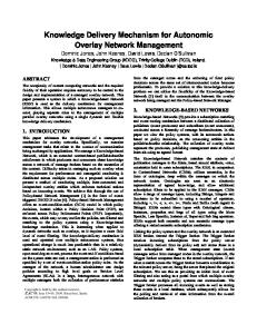
speaking, an SU transmitter splits its transmission power into two parts: one for transmitting its own message, and the other for assisting the transmission of a PU message. The power is split such that at the PU receiver, the quality of the PU signal is not worse than the quality in the absence of SU transmissions. Dirty Paper Coding (DPC) [4] is used to achieve the optimal performance of SUs. However, a number of idealized assumptions are made in [3], which are difficult to satisfy in practice. To see this, consider the system in Fig. 1. For convenience, the PU transmitter, the PU receiver, the SU transmitter, and the SU receiver are called nodes 1 through 4, respectively. The gain of the channel from node i to node j is denoted as hij and is assumed to be deterministic. The noise at node i is assumed to be circular Gaussian with variance Ni and is denoted as Zi ∼ CN (0, Ni ). Node 1 wishes to send message mp to Node 2. Message mp is encoded by encoder Epn () to form codeword Xpn (mp ), a vector of length n. Node 3, which has non-causal knowledge of message mp , wishes to send message ms to Node 4. The SU encoder Esn () encodes mp and ms jointly to form codeword Xsn (mp , ms ). The two codewords Xpn (mp ) and Xsn (mp , ms ) are sent on the interference channel simultaneously. The signals received at Node 2 and at Node 4 are Ypn and Ysn , respectively. The PU decoder Dpn () decodes Ypn to get an estimate m ˆ p for mp , and the SU decoder Dsn () decodes Ysn to get an estimate m ˆ s for ms . PU TX (non-cognitive) Xpn(mp) mp
Enp( )
Z2
PU RX (non-cognitive) Ynp
h12
Node 1
Dpn( )
mp
Node 2
h32 h14
ms
Yns
Ens( )
S2 Xsn(mp,ms)
SU TX (cognitive) Node 3
Dsn( )
ms
h34 Z4
SU RX(cognitive) Node 4
Fig. 1. The overlay approach proposed in [3]. The signal Xsn sent by the SU transmitter is q n Xsn = Xss + (h∗32 /|h32 |)(h12 /|h12 |) ρPs /Pp Xpn ,
(1)
where Pp is the average power of Xpn , Ps is the average power of Xsn , ρ is a constant in [0, 1] representing
the fraction of power used for the PU signal, the factor (h∗32 /|h32 |)(h12 /|h12 |) implements transmit beamforming, n and Xss is the codeword generated by DPC and is circular Gaussian with average power (1 − ρ)Ps . It can be shown that, to not degrade the SNR at the PU receiver, ρ must be at least
ρ∗ =
|h12 |2
�2 �p |h32 |2 Ps (|h12 |2 Pp + N2 ) + N22 − N2 Pp |h32 |2 (|h12 |2 Pp + N2 )2 Ps
(2) An interesting result is that in the “low-interference-gain” √ √ regime, i.e., when |h32 |/ N2 ≤ |h34 | N4 , the capacity of PUs in the presence of SUs is the same as the capacity of PUs in the absence of SUs, and the capacity of SUs in the presence of PUs is the same as the capacity of SUs in the absence of PUs with the SU transmission power being (1 − ρ∗ )Ps . To make the above scheme work, the following idealized assumptions are made, which are difficult to be satisfied in practice: 1. Non-causal knowledge of Xpn at the SU transmitter. To apply DPC, the SU transmitter needs to obtain the PU message Xpn before Xpn is transmitted. 2. Synchronization of the SU transmission and the PU transmission, i.e., the SU signal Xsn and the PU signal Xpn must be aligned in phase precisely. This is difficult to do in practice and turns out to be unnecessary. 3. Knowledge of the channels seen by the PU receiver. From (2), we see that the SU transmitter needs to know channel gains h32 and h12 and noise power N2 . To accurately estimate these parameters, feedback from the PU receiver is needed, which requires modifications to the PUs. Efforts have been made to address these assumptions. In [5], where PUs are DTV systems and SUs are cellular networks, to address the first two assumptions, a DTV distribution network is used to deliver the codewords and transmission timing information to both the TV transmitter and the cellular network, assuming the availability of GPS. However, the use of a DTV distribution network with cellular networks increases system complexity and traffic load in the cellular core network, and the assumption of the availability of GPS may not always hold in practice. The third assumption is partially addressed in [5] by ensuring no degradation in the performance of the critical TV receiver (the one most severely affected by the SU transmission). In [6], solutions above the physical layer are used to circumvent these assumptions in designing an overlay flavored cognitive radio protocol. In this paper, we address the first two assumptions by using techniques at the physical layer. In particular, we leverage the broadcast nature of the wireless medium and the latest advancement in full-duplex radios [7]. The broadcast nature of the wireless medium allows us to use a PU transmission as
a synchronization message. In practice, the effective channel perceived by the PU receiver is multi-tap. To limit the delay spread within the equalization capability of the PU receiver, the SU transmitter needs to send the assisting signal before receiving the entire PU message, which may call for the use of a full-duplex radio. The critical TV (or more generally PU) receiver technique of [5] can be applied on top of our scheme to address the third assumption. The remainder of the paper is organized as follows. Section 2 describes the details of our scheme with analysis. Section 3 provides numerical results, and Section 4 concludes the paper. 2. THE PROPOSED SCHEME The system architecture of our proposed scheme is shown in Fig. 2. Unlike [3][5], our scheme considers fading and does not assume Gaussian codebooks. Also, our scheme does not need a non-causal signal path from the PU transmitter to the SU transmitter or the use of an auxiliary system such as a DTV distribution network. To capture fading, the channel gains hij are now assumed to be circular Gaussian with vari2 2 ance σij and denoted as hij ∼ CN (0, σij ). The propagation delay between node i and j is denoted as τij . The desired message for node 4, ms , is encoded via a causal encoder Es˜n () into Xdn . Our scheme is as follows: 1. The PU transmitter starts sending the PU signal Xpn . 2. Upon overhearing the PU transmission, the SU transmitter demodulates to get the received symbol, performs Tomlinson-Harashima (T-H) precoding [8] (which can be used as a causal interference cancelation scheme) instead of DPC on Xdn (ms ) assuming slow fading, and modulates and transmits the quantization signal. 3. The PU receiver processes the superposed signal as if the SUs were absent in terms of performance, and the SU receiver applies the decoding procedure of T-H precoding to obtain the desired signal. Practical considerations may call for the use of a full-duplex radio at the SU transmitter. The SU transmitter acts as a relay for the PU packet. If the SU transmitter decodes the entire PU packet and then relays the PU packet, the delay spread seen by the PU receiver may be too large to handle. To avoid this problem, the SU transmitter needs to significantly reduce the relay delay. One potential solution is proposed in [9]: if the relay (the SU transmitter in our case) has a 10-dB path loss advantage over the transmitter (the PU transmitter), the relay can decode and then relay the PU packet without waiting for the entire PU packet to be received [9]. However, such 10-dB path loss advantage may not always be available. Besides, many practical systems employ interleaving and CRC of the whole packet which prevents such operation without modifying the PUs. Therefore, the SU transmitter needs to
start relaying while still receiving the PU packet, which calls for the use of a full-duplex radio if the SU transmitter is limited by a small form factor. Although full-duplex radios are traditionally considered infeasible, a two-antenna wideband full-duplex radio is recently demonstrated [7]. PU TX (non-cognitive) Xp
PU RX (non-cognitive)
Z2
Yp
h12
Node 2
Node 1 h13
n
ms
n
ES~( )
h14
Node 3
Xd T-H Precoding etc.
where PTX is the transmit power, N0 is the noise power, h is the channel of any taps, H represents Hermitian, and the expectation E is on h. When h consists �of 1 tap h[0], from (6) � p (1) we have the familiar result Pb = 12 1 − γ0 /(2 + γ0 ) ,
h32
Z3
Ys
h34
Node 4
Xs
SU TX (cognitive, full-duplex)
Z4
SU RX (cognitive)
Fig. 2. System architecture of our proposed scheme. Our scheme naturally introduces delay diversity [10] to the PU receiver. The delay difference ∆τ is τ13 + Tp + τ32 − τ12 , where Tp is the PU symbol interval and accounts for the demodulation delay at the SU transmitter. Note that τ13 + τ32 − τ12 ≥ 0 because the sum of two sides of a triangle is greater than the third side. Thus, ∆τ ≥ Tp and the channel perceived by the PU receiver is two-tap. Also, extra delay can be intentionally added at the SU transmitter. When the channel taps experience independent fading, not only a power gain but also a delay diversity gain can be achieved. In contrast, the work in [5] considers only the power gain. Let lij be τij in number of PU symbol intervals, i, j = 1, ..., 4. For simplicity, lij ’s are assumed to be integers. The signal transmitted by the SU transmitter at time i is Xs [i] = Xss [i] + α(h13 Xp [i − l13 − 1] + Z3 [i])
(3)
where Xss [i] is the quantization signal generated in T-H precoding, and α determines the power split ratio 2 ρ = α2 (σ13 Pp + N3 )/Ps .
(4)
Note that, since the SU transmitter does not decode the primary signal, noise Z3 will be carried on when the SU transmitter performs relay, as shown in (3). The signal received at the PU receiver at time i is Yp [i] =
is obtained by detecting a symbol that is the only transmitted symbol. This lower bound is shown to be within 1dB from the Maximum Likelihood Sequence Estimation (MLSE) performance for QPSK and a two-tap fading channel with equal channel gains. For QPSK, the BER can be shown to be � �q �� Pb = Eh Q hH hPTX /N0 , (6)
h12 Xp [i − l12 ] + αh13 h32 Xp [i − l0 ]
+h32 Xss [i − l32 ] + αh32 Z3 [i − l0 ] + Z2 [i](5) where l0 = l13 + l32 + 1. The delay spread k := l0 − l12 ≥ 1 because ∆τ ≥ Tp . The assisting signal is αh13 h32 Xp [i − l0 ], and the noise is boosted from Z2 [i] to Z2 [i]+αh32 Z3 [i−l0 ]+ h32 Xss [i − l32 ], and we need to determine α and hence the power split ratio ρ so as not to degrade the PU performance. The SU transmitter needs to know the effect of the assistance to the PU receiver in order to determine the power split ratio. We focus on the probability of a bit error (BER) performance, and use the matched filter lower bound [11], which
where γ0 = σ02 PTX /N0 is the average received SNR for the single-tap channel. When h consists of two taps h[0] and h[k], since |h[0]|2 and |h[k]|2 are both exponential and independently distributed, we have the probability density function of v := hH h, fv (v) = (exp(−v/σ02 )−exp(−v/σk2 ))/(σ02 −σk2 ) for v ≥ 0. The BER now becomes � � r �� r 1 1 γ0 γk (2) Pb = 1− γ0 − γk 2 γ0 − γk 2 + γ0 2 + γk (7) where γi = σi2 PTX /N0 , i = 0, k, for γ0 6= γk . When γ0 = (2) γk , the BER is given by the limit limγ0 →γk Pb . At high (2) SNRs, i.e., γ0 , γk � 1, we have Pb ≈ 3/(4γ0 γk ), which clearly shows the delay diversity gain. For the problem at hand, when overlay is not used at all, the channel is one-tap h[0] = h12 , and the BER is � � p (1) P˜b = 1 − γ0 /(2 + γ0 ) /2, (8)
2 where γ0 = σ12 Pp /N2 . When our overlay scheme is used, the channel is two-tap with h[0] = h12 and h[k] = αh13 h32 and the received quantization signal h32 Xss is Gaussian and serves as interference, and the BER becomes s s !! 1 1 γ ˜ γ ˜ 0 k (2) P˜b = 1− γ˜0 −˜ γk 2 γ˜0 − γ˜k 2 + γ˜0 2 + γ˜k
(9)
2 2 2 where γ˜0 = σ12 Pp /(N2 + σ32 (1 − ρ)Ps + α2 σ32 N3 ), γ˜k = 2 2 2 2 2 2 α σ13 σ32 Pp /(N2 + σ32 (1 − ρ)Ps + α σ32 N3 ), and α is defined in (4). When the scheme in [5] is used, where the two taps now collapse into one and the noise Z3 is not present in the relay signal, we have the BER � � p (1) Pˆb = 1 − γˆ0 /(2 + γˆ0 ) /2, (10) 2 2 2 where γˆ0 = (σ12 Pp + ρσ32 Ps )/(N2 + σ32 (1 − ρ)Ps ). (1) The SU transmitter now calculates ρ for which P˜b = (2) P˜b . Such ρ may not exist because the received PU signal h13 Xp at the SU transmitter could be much weaker than the
noise Z3 . If such ρ does not exist, the SU transmitter cannot use our proposed overlay scheme. If such ρ exists, denoted as ρ∗ , the SU transmitter sets ρ ≥ ρ∗ and applies our proposed overlay scheme. The SU transmitter now performs T-H precoding. In particular, the SU transmitter determines the quantization signal Xss [i] in (3) which depends on the ”known interference” S[i] = h34 α(h13 Xp [i − l13 − 1] + Z3 [i]).
(11)
Since the PU TX, the SU TX and the SU RX form a triangle, i + l34 − l14 > i − l13 − 1. The SU TX cannot know the PU signal directly transmitted by the PU TX and received at the SU RX at time i + l34 − l14 early enough for T-H precoding and thus signal h14 Xp [i + l34 − l14 ] is not part of the ”known interference”. T-H precoding [8] is then applied to obtain Xss [i]. The received signal at the SU RX is Ys [i] = S[i − l34 ] + h34 Xss [i − l34 ] + Z4 [i]. Let the constellation of the desired received QPSK signal at the SU RX be A(±1 ± j). If S[i − l34 ] is totally random (i.e., 2-dimensional uniform distributed), then A is determined by Pss = (1 − ρ)Ps = 2A2 /(3||h34 ||2 ). 3. NUMERICAL RESULTS We compare the BER performance of our scheme and that of the one in [5]. The power split ratio ρ is determined for the scheme in [5] by solving ρ for which γ0 = γˆ0 . The same value of ρ is then applied to our scheme. The PU receiver uses the Viterbi algorithm to perform MLSE. We set Pp = 2 Ps , σij = σi20 j 0 , Ni = Ni0 for all i, j, i0 , j 0 and vary γ0 = 2 σ12 Pp /N2 . The performance for the scheme in [5] is the same as Rayleigh fading. Figure 3 shows that our scheme (red solid line with triangles) offers a delay diversity gain, which is able to compensate for the penalty due to its use of the amplifyand-forward relay approach. In addition, at high SNR, our scheme significantly outperforms the one in [5]. 0
10 BER at the PU receiver
−1
10
posed in information theory by leveraging the broadcast nature of the wireless medium and the latest advancement in full-duplex radios. In addition, our scheme naturally offers delay diversity which can significantly improve the performance of the PU receiver. 5. REFERENCES [1] S. A. Jafar, S. Srinivasa, I. Maric, and A. Goldsmith, “Breaking spectrum gridlock with cognitive radios: An information theoretic perspective,” Proceedings of the IEEE, vol. 97, no. 5, pp. 894–914, May 2009. [2] I. F. Akyildiz, W.-Y. Lee, and K. R. Chowdhury, “CRAHNs: Cognitive radio ad hoc networks,” Ad Hoc Networks, vol. 7, no. 5, pp. 810–836, July 2009. [3] A. Jovicic and P. Viswanath, “Cognitive radio: An information-theoretic perspective,” in IEEE ISIT, Seattle, WA, July 2006, pp. 2413 – 2417. [4] Max H. M. Costa, “Writing on dirty paper,” IEEE Trans. Info. Theory, vol. IT-29, no. 3, pp. 439–441, May 1983. [5] J. Sachs, I. Maric, and A. Goldsmith, “Cognitive cellular systems within the tv spectrum,” in IEEE DySPAN, Singapore, April 2010. [6] L. Ma, C. C. Shen, and C. Xin, “CONI: Credit-based overlay and interweave dynamic spectrum access protocol for multi-hop cognitive radio networks,” in IEEE Globecom, Houston, TX, Dec. 2011. [7] M. Jainy, J. Il. Choiy, T. M. Kim, D. Bharadia, S. Seth, K. Srinivasan, P. Levis, S. Katti, and P. Sinha, “Practical, real-time, full duplex wireless,” in MobiCom, Las Vegas, Nevada, Sept. 2011. [8] H. Harashima and H. Miyakawa, “Matchedtransmission technique for channels with intersymbol interference,” IEEE Trans. on Comm., vol. Com-20, no. 4, pp. 774–780, Aug. 1972.
−2
10
[9] P. Mitran, H. Ochiai, and V. Tarokh, “Space-time diversity enhancements using collaborative communications,” IEEE Trans. on Info. Theory, vol. 51, no. 6, pp. 2041–2057, June 2005.
−3
10
−4
10
−5
10
−6
10
0
Theoretical for the scheme in [5] Simulation for the scheme in [5] Matched filter lower bound for our scheme Simulation for our scheme 5
10
15 γ0 (dB)
20
25
30
Fig. 3. The BER performance at the PU receiver.
4. CONCLUSION We address the non-causal and the synchronization assumptions of the overlay cognitive radio approach originally pro-
[10] N. Seshadri and J. H. Winters, “Two signaling schemes for improving the error performance of frequencydivision-duplex (fdd) transmission systems using transmitter antenna diversity,” in IEEE VTC, 1993. [11] J. E. Mazo, “Exact matched filter bound for two-beam rayleigh fading,” IEEE Trans. on Comm., vol. 39, no. 7, pp. 1027–1030, July 1991.