Computer Communications 29 (2006) 611–617 www.elsevier.com/locate/comcom
Macro/micro-mobility fast handover in hierarchical mobile IPv6 M.H. Habaebi* Computer Engineering, Faculty of Engineering, Alfateh University, Afurnaj Campus—Tripoli, P.O. Box 83416, Tripoli, Libyan Arab Jamahiriya Received 27 February 2003; revised 29 November 2004; accepted 7 December 2004 Available online 21 December 2004
Abstract Mobile Internet Protocol version 6 (MIPv6) has been proposed to solve the problem of mobility in the new era of Internet by handling routing of IPv6 packets to mobile nodes that have moved away from their home network. Users will move frequently between networks, as they stay connected to the Internet. Thus, as mobility increases across networks, handovers will significantly impact the quality of the connection and user application. However, MIPv6 only defines means of managing global (macro)-mobility but does not address micro-mobility separately. Instead, it uses the same mechanism in both cases. This involves long handover delay and signaling load. The Hierarchical Mobile IPv6 (HMIPv6) protocol has been proposed as an extension of basic MIPv6 to solve this problem by splitting the handover management into macro-mobility and micro-mobility schemes. HMIPv6 introduced a new protocol agent called Mobility Anchor Point (MAP) to manage mobility and serve as a local entity to aid in mobile handover. The handover (or registration) operation is the operation when MN registers its presence to its Home Agent (HA) and Correspondent Node (CN). This paper proposes a mechanism to perform fast handover in HMIPv6 by adopting the multicast technique to the MAP for both macromobility and micro-mobility management. Our proposal is designed to minimize service disruption that occurs during the registration operation. We simulate the performance using network simulator (NS-2) and we present and analyze the performance testing for our proposal by comparing it with the basic hierarchical mobile IPv6. The results show that our scheme allows the MN to receive packets faster than the basic HMIPv6. q 2005 Elsevier B.V. All rights reserved. Keywords: Mobility anchor point; Correspondent node; Micro-mobility
1. Introduction There has recently been almost universal recognition that Mobile IP [1], the current standard for IP-based mobility management, needs to be enhanced to meet the needs of future cellular environment. Mobile IP supports user mobility in the network layer that allows mobile IP to be transparent to other layers. However, Mobile IP has several drawbacks. IETF introduced Mobile IPv6 as the successor of Mobile IPv4 and every drawback in Mobile IPv4 are solved in Mobile IPv6 [2]. Although Mobile IPv6 supports mobility, several mobility requirements have not been achieved. The list of main requirements specific to an IPbased mobility management protocol are as follows [3]:
* Tel.: C218 91 3725514; fax: C218 21 3340761. E-mail address:
[email protected] 0140-3664/$ - see front matter q 2005 Elsevier B.V. All rights reserved. doi:10.1016/j.comcom.2004.12.004
† Hierarchical structure—to localize scope of location updates, † Support seamless Handover—Packet redirection with minimal delay, and † Provides compatibility with QoS such as support for real time applications Mobile IPv6 faces some problems due to its handover management. The problems occurs when a mobile node moves from one access point to another access point in a small coverage area (micro-mobility), which reduces frequent handover, such that MIPv6 will not be suitable for such scenario under that circumstances. MIPv6 generates significant amount of signaling traffic in the core network, even for local movement, followed by long interruption during the handover. Hierarchical Mobile IPv6 (HMIPv6) [4] proposed as an extension to the basic Mobile IPv6 in order to solve these
612
M.H. Habaebi / Computer Communications 29 (2006) 611–617
List of acronyms HMIPv6 hierarchical mobile internet protocol version6 MAP mobility anchor point HA home agent CN correspondent node NS-2 network simulator version 2 MN mobile node
problems in mobile IPv6. It does this by splitting the mobility management into macro- and micro-mobility. Even though it may reduce the handover delay and overhead in term of bytes or packets but it still suffers from long delays. In this paper we describe a modification to hierarchical mobile IPv6 to support fast handover by adopting the multicast mechanism in HMIPv6 protocol. The remainder of this paper is organized as follows: Firstly, the nature of the problems pertinent in Mobile IPv6 is discussed. Secondly, a brief review of Mobile IPv6 and HMIPv6 is presented. Thirdly, a description of our proposed solution for HMIPv6 macro/micro-mobility management is introduced. Fourthly, simulation results and performance testing is presented. And finally the paper is concluded in Section 5.
2. Mobility management in MIPv6 Mobile IPv6 protocol consists of a home agent (HA) that serves the mobile node (MN) when it is within home network and access router (AR) advertises the address every time an MN moves into its network. When the MN wants to roam to foreign network, the MN will acquire a new care of
Fig. 1. Registration operation in mobile IPv6.
AR BU DAD LcoA RcoA
access router binding update duplicate address detection local care of address regional care of address
address (CoA) advertised by AR. The MN then register its new CoA to its HA and CN. This is done as follows: 1. MN sends binding update message (BU) to HA and CN through the new access router (AR). 2. The new AR begins to act as proxy so that it can perform the duplicate address detection (DAD) checks. If DAD check is successful, the new AR must send binding acknowledgement (B_ack) to MN, confirming the address validation. 3. After MN receives B_ack, it sends BU to CN and HA. The problem arises when the HA or CN is located geographically far away from the MN (see Fig. 1). The message exchange transmission time for MN to send BU to HA/CN will become very high causing long delays or service disruptions. HMIPv6 improves the handover management of basic Mobile IPv6 by introducing the new protocol agent MAP. MAP splits the management of the handover process into macro-mobility and micro-mobility and deals with them separately. HMIPv6 improvement over Mobile IPv6 is noticeable especially in the micro-mobility where the coverage area is small and the handover is frequent. HMIPv6 reduces the signaling over radio interface and supports more efficient handover. Macro-mobility handover happens when MN moves globally from one MAP to another MAP that is located far away from each other while micro-mobility handover
Fig. 2. Mobility management in HMIPv6 network.
M.H. Habaebi / Computer Communications 29 (2006) 611–617
happens when MN moves locally between access router within one MAP domain. In HMIPv6, MN is assigned two addresses, regional care of address (RCoA) and on-link care of address (LCoA). These two addresses are very useful for managing macro-mobility and micro-mobility (see Fig. 2).
3. Proposed macro/micro-mobility management scheme To further reduce the handover delay in HMIPv6 protocol, we propose two separate modifications for both handover mobility schemes. 3.1. Macro-mobility management The HMIPv6 macro-mobility management is explained by modeling the routing scheme for every message exchange between MN and its correspondent agent (CN). The over-all delay is dependent of the time required for each step in the registration operation which in-turn depends mainly on the transmission time between the nodes. The message exchange for this operation is shown in Fig. 3. We assume the scenario that the MN is currently receiving packets from CN and starts to move to a new MAP domain. After the MN receives router advertisements, it acquires two new addresses, the RCoA and LCoA. The description for each message exchange is as follows: 1. Mobile node sends binding update (BU) to mobility anchor point (MAP) through access router (AR). MN needs to configure two care of addresses: An RCoA and LCoA, 2. AR receives BU and sends to MAP,
Fig. 3. Macro-mobility handover routing scheme (dotted line represents wireless connection).
613
3. MAP receives the BU and will perform duplicate address detection (DAD) check. During this time MN must wait for the check, 4. MAP sends binding acknowledgement (B_ack) to MN through AR. B_ack is used to indicate that it has successfully received MN’s BU and the address is not duplicated, 5. AR sends B_ack and MN received it, 6. Subsequently MN sends BU to CN through AR and MAP. This BU is used to inform the CN or HA to change their destination address for the packets belongs to MN, 7. AR receives BU and send to MAP, 8. MAP receives and send BU to CN, 9. CN receives the BU and changes the destination address from the old RCoA to new RCoA CN sends the packets to MN through MAP based on MN’s new RCoA, 10. MAP receives packets addressed to the MN’s RCoA. Packets will be encapsulated and tunneled from the MAP to MN through AR based on MN’s LCoA. 11. AR sends packet to MN. After the MN receives packets from CN, it de-capsulates the packets and then process them in the normal manner (this means the registration operation is done). 3.2. Proposed multicast scheme in macro-mobility management In HMIPv6, the delay comes from the DAD check and the message exchange transmission time during the process of the registration operation. We propose a multicast technique that is designed to minimize the service disruption delay occurring during the registration operation. Now assume the scenario depicted in Fig. 4. The MN is within MAP1 specifically within AR3 and has an RCoA1 and LCoA3 and CN is currently sending packets to MN. When MN reaches the edge of MAP1 coverage area, MN sends control message to MAP1 requesting it to build a multicast group for the MN. MAP1 receives the control message and constructs a multicast group for the MN and then send a message to the adjacent AR (in this case are AR2 and AR4) to join multicast group. Thus when there are on-going packets, addressed to MN, in the network, MAP1 will multicast the packet to AR2 and AR4. If there is any request messages from the MN, the ARs forward the packets based on MN’s unique interface identifier. When MN examines that it receives the router advertisement from AR4, the MN acquires two addresses, e.g. RCoA2 and LCoA4. Then MN must register its presence with the HA and CN. And similar to HMIPv6, we can explain the registration operation (see Fig. 5) as follows: 1. MN sends binding update (BU) and request message to AR4 to request AR4 to forward the packets
614
M.H. Habaebi / Computer Communications 29 (2006) 611–617
Fig. 4. Proposed multicast scheme for HMIPv6 macro-mobility management.
2. AR4 receives request message and BU. AR4 forward the multicast packets based on MN’s unique interface identifier. Simultaneously AR4 sends BU to MAP for DAD check. MN receives temporary multicast packet from AR4 until registration operation completes. 3. MAP2 receives BU, perform DAD check. 4. MAP2 finishes the DAD check and then changes the destination address of MN from (RCoA1, LCoA3) to (RCoA2, LCoA4) and sends binding acknowledgement (B_ack) to MN. 5. AR4 receives B_ack and sends to MN 6. MN receives B_ack, containing the validation of RCoA2 and LCoA4, and sends BU to CN to inform CN about its new addresses. 7. AR4 receives BU and sends it to MAP2 8. MAP2 receives BU and send to CN 9. CN receives and changes the MN’s old RCoA (RCoA1) to MN’s new RCoA (RCoA2) and send the packets to MN. 10. MAP2 receives packets addressed to the MN’s RCoA2 and sends to MN through AR4 based on MN’s LCoA4. 11. AR4 receives the packets and sends to MN. Consequently with this scheme, the new AR will have a copy of the on-going packets when the MN is still within old MAP. When the MN moves to a new MAP, the new AR starts forwarding the packets to MN during the registration operation.
3.3. Micro-mobility management In this case, MN moves locally between AR within the same MAP domain. MN only changes its LCoA but its RCoA remains unchanged and it does not have to send BU to CN/HA to inform it about its new address (see Fig. 6). The registration process is performed as follows: 1. MN sends BU to MAP through AR, 2. AR sends BU to MAP,
Fig. 5. Proposed multicast scheme for macro-mobility.
M.H. Habaebi / Computer Communications 29 (2006) 611–617
615
3.4. Proposed multicast scheme in micro-mobility management
Fig. 6. Micro-mobility handover routing scheme.
3. MAP performs duplicate address detection (DAD) check, 4. DAD finished, MAP sends B_ack to MN through AR. If there is any packet addressed to MN’s RCoA, MAP will encapsulate and tunnel the packets and sends to MN through the new AR based on MN’s new LCoA. 5. AR sends packets to MN. The MN de-capsulates the packets and then process the packets in the normal manner. When the MN moves locally within MAP domain, MN does not have to send binding update to CN or HA since CN/HA sends packets based on MN’s RCoA, and subsequently, MAP sends packets to the MN as described before. Unlike basic Mobile IPv6, where MN roaming in a small coverage area (micro-mobility) still needs to send BU to CN/HA that could be located far away from it.
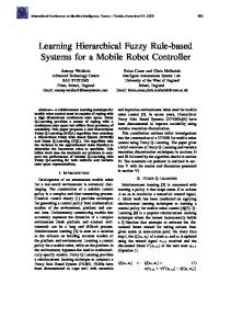
Assume the scenario for our proposed multicast scheme as depicted in Fig. 7. Currently the MN is within MAP2, specifically within AR5 and having a address pair, e.g. RCoA2; LCoA5, and CN is sending packets to MN. When MN is on the edge of AR5 coverage area, MN sends control message to MAP2 requesting it to build a multicast group for the MN. After receiving control message, MAP2 constructs a multicast group for the MN and sends a request message to AR4 and AR6 to join the multicast group. When the on-going packets addressed to MN arrive, MAP2 will multicast these packets to AR4 and AR6. If there is any request message from MN, the ARs will forward the packets based on MN’s interface identifier. When the MN examines the beacon of the router advertisement from AR6, the MN acquires new address, e.g. LCoA6. Then the MN performs the registration operation for registering its presence to HA and CN. We can explain the registration operation by modeling the routing scheme for every message exchanged between MN and its correspondent agent (HA/CN). The detailed scheme is shown in Fig. 8. 1. MN sends binding update (BU) and request message to AR6 2. AR6 forwards the multicast packets to MN based on MN’s interface identifier and simultaneously send BU to
Fig. 7. Proposed multicast scheme for hmipv6 micro-mobility management.
616
M.H. Habaebi / Computer Communications 29 (2006) 611–617
Fig. 8. Proposed multicast scheme for HMIPv6 micro-mobility.
3. 4.
5. 6.
MAP2. MN will receive the multicast packets from AR6 until the registration operation completed. MAP2 perform DAD check MAP2 finishes the DAD check and then changes the destination address of MN from (RCoA2, LCoA5) to (RCoA2, LCoA6), MAP2 sends Binding Acknowledgement (B_ack) to MN with address validation and packet addressed to MN AR6 receives the B_ack then stop sending the multicast packet and start to send packets to MN using MN’s address (LCoA6).
4. Simulation setup and performance testing The simulation study presented in this paper uses the Columbia IP Micro-mobility Software [4], which supports separate models including Hierarchical Mobile IP together
Fig. 9. Handover delay for HMIPv6 networks for different bandwidths and link delays in a macro-mobility network.
Fig. 10. Handover delay for proposed multicast scheme for different bandwidths and link delays in a macro-mobility network.
with detailed description, online source code and documentation. We have implemented the proposed multicast schemes for macro/micro-mobility management extensions into the HMIPv6 described in [4] using the NS-2 network simulator version 2.1b [5]. NS-2 allows the user to configure the parameters of the topology that is already supported by NS-2 flexibly. We have modified the AR source codes to accommodate the extension changes described in the proposed schemes above. All simulation scenarios are based on Figs. 4 and 7. The registration operation process of the mobile IPv6 handover starts when the MN sends binding update to its new access router until MN receives any packet addressed to it. The objective of these simulations is to find out the time for the MN to re-establish the communication that it has started from the time the MN sends the BU message until the time when the MN receives packets from its new AR. This time difference is defined as the handover
Fig. 11. Handover delay for HMIPv6 for different bandwidths and link delays in a micro-mobility network.
M.H. Habaebi / Computer Communications 29 (2006) 611–617
Fig. 12. Handover delay for proposed multicast scheme for different bandwidths and link delays in a micro-mobility network.
delay. We used NS-2 to test the performance of the four proposed multicast schemes. In order to simulate the real traffic, we set up the Correspondent Node (CN) as a traffic source of a Constant Bit Rate (CBR) source over a User Datagram Protocol (UDP), producing fixed length packets of 200 bytes each every 20 ms. This simulates a host that is streaming audio or Voice Over Internet Protocol (VoIP) traffic. Then the mobile node acts as a sink receiving packets from CN. The setup link topology consists of a wired link and a wireless link. The wired link is fixed and used to connect the CN to the mobility anchor point (MAP) and MAP to the access router (AR). The bandwidth of the wired link is set to 100 Mbps and its link propagation delay is set to 2 ms. To gauge the handover delay performance of our scheme for different possible wireless networks, we performed our simulation using wireless networks of different link delays and different bandwidths. Our simulation uses the IEEE 802.11 2.4 GHz standard that is already supported by Ns-2 for the wireless links with various bandwidth levels from 1; 2; to 5.5 Mbps. This allows for bandwidth guarantee for all mobile Node using standard models such as diffserv and dynamic QoS. The access scheme of the mobile hosts to connect to the Access Points in our simulation is the carrier sense multiple access with collision avoidance (CSMA/CA) wireless link model were each AP operates on a different frequency band. We have assumed a seamless migration from 3G to 4G using IPv6 Protocol therefore the coexistence issues of 3G and 4G were not considered in this paper. For macro-mobility network we vary the link delay from 10 to 50 ms for link delay and for micro-mobility network we vary it from 1 to 10 ms and the bandwidth for both macro and micro-mobility scenarios were set each time at a different level such as 1, 2 and 5.5 Mbps, respectively.
617
Figs. 9 and 10 represent the performance of handover delay for a macro mobility network for HMIPv6 and our proposed multicast scheme, respectively. We can see from the graphs that for a typical wireless network of 2 Mbps and 20 ms link delay, in HMIPv6, MN must wait for about 300 ms to start receiving the packets from the correspondent node since MN sends BU to its new access router. For our proposed multicast scheme, MN must wait for about 100 ms only to start receiving the packets, a savings of 200 ms. Figs. 11 and 12 represent the performance of handover delay in a micro-mobility network for HMIPv6 and our proposed multicast scheme, respectively. As shown in the Fig. 11, for a typical wireless network of 2 Mbps bandwidth and 10 ms link delay, in HMIPv6 micro-mobility, the MN must wait for about 160 ms to start receiving the packets from its correspondent node while for our multicast scheme, MN only must wait for about 43 ms. We can also see from the figures that the handover delay results that for HMIPv6 macro-mobility and HMIPv6 micro-mobility, with the typical wireless link delay of 10 ms, the HMIPv6 network can minimize the handover delay for an MN lying within small coverage area.
5. Conclusion In this paper we have proposed a scheme to perform fast handovers for hierarchical mobile IPv6 networks in the macro-mobility and micro-mobility management. Fast handover performance is achieved by forwarding the multicast packets from the mobility anchor point to every adjacent access router. We have simulated the performance in NS-2 network simulator. From the simulation results, we have shown that our proposal allows the MN to receive packets faster than the HMIPv6 scheme. Issues like how could our proposed mechanisms support coexistence between legacy and future networks and provide bandwidth guarantees were not considered in this paper but it is proposed for future work.
References [1] C. Perkins, IP Mobility Support for IPv4, revised draft-ietf-mobileiprfc2002-bis-08.txt, IETF, September 2001. [2] J.D. Solomon, Mobile IP—the Internet Unplugged, Prentice Hall, Englewood cliffs, NJ, 1998. [3] P. de Silva, H. Sirisena, A mobility management protocol for IP-based cellular networks, Proceedings of IEEE ICCCN, Scottsdale AZ, October, 2001. [4] H. Soliman, C. Castellucia, K. Elmalki, L. Bellier, Hierarchical MIPv6 Mobility Management (HMIPv6), Internet Draft, July 2001, draft-ietfmobileip-hmipv6-05.txt, work in progress. [5] http://www.ISI.edu/nsnam/ns