652
IEEE JOURNAL OF SOLID-STATE CIRCUITS, VOL. 35, NO. 4, APRIL 2000
Low-Power CMOS Digital Design with Dual Embedded Adaptive Power Supplies Tadahiro Kuroda and Mototsugu Hamada
Abstract—A low-power CMOS design methodology with dual embedded adaptive power supplies is presented. A variable supply-voltage scheme for dual power supplies, namely, the dual-VS scheme, is presented. It is found that the lower supply voltage should be set at 0.7 of the higher supply voltage to minimize chip power dissipation. This knowledge aids designers in decision of the optimal supply voltages within a restricted design time. An MEPG-4 video codec chip is designed at 2.5 and 1.75 V for internal circuits that are generated from an external power supply of 3.3 V by the dual-VS circuits. Power dissipation is reduced by 57% without degrading circuit performance compared to a conventional CMOS design. Index Terms—Adaptive power-supply system, clustered voltage scaling, low-power CMOS design, multiple supply voltages.
I. INTRODUCTION
L
OWERING the supply voltage is an effective way to reduce power dissipation, but it causes two design problems. One problem is that chip throughput is degraded due to increased circuit delay at reduced voltages. Employing only for noncritical multiple supply voltages to lower circuits is one approach to maintain the chip throughput. A clustered voltage scaling (CVS) scheme has been proposed [1] in order to minimize area and delay penalties caused by insertion of level-converters at boundary from lower to higher ’s. The other problem in lowering is that many power supplies are required on a board, because optimal voltages vary chip by chip depending upon performance requirements and circuit types, and they change even with time as workload changes. Furthermore, interface between chips under different supply voltages requires complicated and expensive circuits and device structures. One solution is to employ a universal supply voltage for the interface circuits, while generating the individual optimal voltages for internal circuits by an embedded dc–dc converter [2], [3]. A variable supply-voltage (VS) scheme [3] monitors circuit speed using a critical path replica and generates the lowest supply voltage by a feedback control so as to adjust the monitored circuit delay to the cycle time of an input clock. In theory, the VS scheme and the CVS scheme should be able to be applied together to yield a multiplier effect, but in practice, design issues may arise. For instance, in the CVS scheme, a critical path may consist of circuits under multiple supply voltages. If a critical path replica is implemented with a combination of the multiple supplies, the feedback control Manuscript received December 11, 1998; revised November 30, 1999. The authors are with the System ULSI Engineering Laboratory, Mobile & Network LSI Development Group, Toshiba Corp., Kawasaki 210-8520 Japan (e-mail:
[email protected]). Publisher Item Identifier S 0018-9200(00)02869-9.
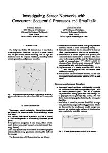
Fig. 1. Dual-VS scheme.
in the VS scheme may be unstable because increased delay caused by lower voltage of one of the supplies may be offset by higher voltage of another supply. Even with multiple different replicas, interaction may occur between the multiple supplies due to delay in the feedback control. Another issue in the CVS scheme is that design cannot start until supply voltages are decided, and it takes a long time to determine optimal supply voltages. In using dual supply voltand , for example, the lower the , the lower ages of the power dissipation per gate under , but the fewer the gates due to the slower circuit speed. It is therefore considfor for minimizing total power ered that there exists an optimal dissipation. In order to find the optimal , all the design tasks should be performed repeatedly, changing , characterizing library, partitioning circuits, designing layout, and monitoring the power dissipation. In this paper, a low-power CMOS design methodology is presented where dual supply voltages are adaptively generated and optimally provided to internal circuits. The VS scheme for dual power supplies, namely, the dual-VS scheme, is proposed. A is presented, which aids designers theory about the optimal in deciding on the optimal supply voltages. In Section II, the dual-VS scheme is proposed. The theory of is presented in Section III. An MPEG-4 video the optimal codec chip is developed, and its evaluation results are reported in Section IV. Section V is dedicated to conclusions. II. DUAL-VS SCHEME The dual-VS scheme is illustrated in Fig. 1. There are two ( cell) and the other circuit clusters: one operating under ( cell). and are generated by an embedded under
0018–9200/00$10.00 © 2000 IEEE
IEEE JOURNAL OF SOLID-STATE CIRCUITS, VOL. 35, NO. 4, APRIL 2000
653
When
, the power dissipation is given by (1)
where is the operating frequency and is the capacitance. under dual power supplies, the power dissipaWhen tion becomes (2) is total capacitance of the cells and is total where cells. The power dissipation ratio is then capacitance of the given by Fig. 2.
Level-conversion flip-flop.
(3) power supply and , respectively. Each of them monitors circuit speed of a critical path replica under its generating voltage for an adaptive control. Both flip-flops and clock circuits to reduce power dissipation. It is thereare operated under fore necessary to insert level-converters between the flip-flops cells. and the A circuit that functions as both the flip-flop and the level converter, the level-conversion flip-flop (LC-F/F) in Fig. 2, is developed [4]. When a clock CLK is high ( ), n-channel transistors and are turned off, and the slave is equivalent to a conventional level-conversion circuit. At this time, the master is holding data that passes to the level-conversion circuit. When CLK is low, and are turned on, and the slave is equivalent to a latch. At this time, the master is transparent but disconnected from the slave. Therefore, data when CLK was high are stored in the slave and output. In this way, at the rising CLK edge, -swing data -swing are captured which will be stored and converted to the signal for output till the next CLK edge. Power, delay, and area of LC-F/F are smaller than those of the conventional flip-flop plus level-converter by 14, 41, and 26%, respectively. For stable control, consider two virtual critical paths, each of cells or the cells and whose which is composed of only the delay is equal to or a little slower than the real critical path. Now consider controlling the virtual critical paths by putting them and . The dual supplies can in the replica circuits in be controlled independently and hence stably. The critical path and are implemented by a gate chain. The replicas in number of the stages of the gate chains is designed such that delay of the two critical path replicas is equal to (in practice a little bigger for safety margin than) the cycle time at the optimal and . In other words, the ratio of the number of the stages of the gate chains is inversely proportional to the ratio of the gate and . Consequently, the gate delay delay at the optimal is proportional to the gate delay under , and thus the under relative delays of all the real paths are maintained. It is, therefore, guaranteed that no new critical path appears that is slower than the virtual critical path. The stability and error of this control scheme are examined through chip evaluation in Section IV. III. THEORY should be chosen to minimize power dissipation of circuits. In this section, a theory that deals with optimal is studied.
From an observation that the slower path may often contain many more cells, it can be assumed as a first-order approximation that capacitance in a path is proportional to the delay of the is given by path. Consequently,
(4)
is a path-delay distribution function and is a ratio of the total delay of the cells ( ) to . represents the normalized the total path delay at . The path number of path whose delay is when ), and is delay is normalized by the cycle time ( normalized as
where
(5) At
,
is slower, and the total path delay becomes (6)
is a representative delay function of the supply where voltage and can be obtained by measurement or simulation. cells As many cells as possible should be assigned as the to minimize the power dissipation within a budget of the cycle ). Given in (6), is given by time ( (7)
From (3) to (5) and (7), the power ratio can be calculated as when is provided. a function of The power ratio is calculated for five artificial examples depicted in Fig. 3. Interestingly, becomes minimum of for all the examples, even though at ’s between 0.6–0.7 . This means that the minimum value of depends on should always be set at around 0.6–0.7 to minimize the power dissipation. In order to verify this theory, a discrete cosine transform (DCT) block composed of 5466 cells in an MPEG-4 video codec [4] is designed by using a proprietary electronic design
654
IEEE JOURNAL OF SOLID-STATE CIRCUITS, VOL. 35, NO. 4, APRIL 2000
Fig. 3. Power reduction ratio versus V =V
Fig. 4.
Fig. 5. Path-delay distribution before and after dual-VS scheme in MPEG-4 video codec submodules. calculated from theory.
Simulated power dissipation dependence on V =V
in DCT block.
automation (EDA) tool [5] for the CVS scheme at various ’s, and the power dissipation is monitored. As shown in Fig. 4, the experimental result shows a good agreement with the theory of lambda-shape is assumed. when IV. MPEG-4 VIDEO CODEC CHIP An MPEG-4 (Moving Picture Experts Group phase 4) video codec chip [4] has been designed by employing the dual-VS of 2.5 scheme. The dual-VS scheme typically generates 5% V and of 1.75 5% V for 30-MHz operation from 10% V. All the memories an external power supply of 3.3 . Threshold voltage is controlled by the are operated under of 0.1 VTCMOS technology [6]. The chip is fabricated for 0.1 V, and the VTCMOS technology adjusts to 0.2 0.05 V in the active mode and 0.5 0.05 V in the standby mode. The control circuits for the dual-VS scheme and the VTCMOS technology are placed at four corners of the chip. A cell row cells in the standard cell layout is dedicated either for the row) or the cells (called the row). The (called the row. level-conversion flip-flops (LC-F/F’s) are placed in the for power supply, which The master latch of LC-F/F requires
is provided from the adjacent row by a signal interconnection. Since LC-F/F can receive a -swing clock, clock buffers row to reduce power dissipation for the are placed in the clock distribution. The layout result of the MPEG-4 chip for the dual-VS scheme is only 5% larger than that for the conventional layout. Details of chip design and design methodology may be found in [4] and [5]. Cell number, cell area, and row number in the logic layout of the chip are summarized in Table I. 68% of the cells are recells. The number of the cells is about placed with the cells, which agrees with the simulation result in 1/3.5 of the Fig. 4. Since relatively large LC-F/F’s are also placed in the rows, total cell area in the rows is about the same as that rows. Accordingly, the total number of the row in the row. If they differ much in number, inbalances that of the terconnection length between them will be increased. From the of 0.7 layout viewpoint, it is more desirable to choose rather than 0.6 . Power dissipation of the MPEG-4 chip is simulated by a transistor-level power analysis tool with test vectors for practical operations. With the VS scheme and the VTCMOS technology, the power-supply voltage can be lowered to 2.5 from 3.3 V so that power dissipation is reduced by 43% in all the circuits. When the dual-VS scheme is applied to further lower the supply voltage of noncritical circuits to 1.75 V, power dissipation is further reduced by 25%. The breakdown of the power reduction is: 30% in logic gates, 37% in flip-flops, and 51% in clock distribution. The fabricated chips are measured by a tester with test vectors for practical operations. The average power dissipation is 62 mW in the chip with the VS scheme and 45 mW in the chip with the dual-VS scheme, excluding power penalties of dc–dc converters. The power penalty is 10 and 15 mW for the VS scheme and the dual-VS scheme, respectively. In order to investigate how much a surplus of timing in the noncritical path is exploited to reduce power dissipation, path delay distribution is investigated by a static timing analyzer in nine submodules in the MPEG-4 chip, and the result is depicted in Fig. 5. The horizontal axis is path delay normalized by the cycle time, and the vertical axis is the normalized number of paths. The average path delays increase from 0.31–0.51 to 0.41–0.69 of the cycle time by the dual-VS scheme. It can be
IEEE JOURNAL OF SOLID-STATE CIRCUITS, VOL. 35, NO. 4, APRIL 2000
655
TABLE I MPEG-4 LAYOUT RESULT. F/F: SLLC-F/F; LC: LEVEL CONVERTER
aids designers in deciding on the optimal supply voltages, which is essential for short design time. An MEPG-4 video codec chip is designed at 2.5 and 1.75 V for internal circuits that are generated from an external power supply of 3.3 V. Sixty-eight percent of the cells, which occupy 50% in area, are operated under . Half of the total power dissipation is therefore reduced to 0.7 , which results in 25% power reduction compared to a design at 2.5 V with the conventional VS scheme. The power is 57% less than that for a conventional CMOS design at 3.3 V. The chip area overhead is only 5%. ACKNOWLEDGMENT
Fig. 6.
Shmoo plot of DCT module in MPEG-4 video codec.
understood that the amount of the shift of the path delay distribution is utilized for power reduction by lowering the supply voltage. and in A shmoo plot in Fig. 6 is obtained by changing the DCT module. It is shown that the minimum supply voltages and with safety margin for 30-MHz are generated for operation. No problem in terms of stability and error of the is lowered dual-VS scheme has been observed. When to around 0.5, function error occurs. This function error may be to . As long as caused by crosstalk noise from is around 0.7, the function error does not occur. It is true, how, the bigger the crosstalk noise ever, that the lower the and its influence on signal propagation delay. Maximum operating speed may be degraded to some extent. V. CONCLUSIONS The dual-VS scheme is presented. Implementation of a critical path replica for stable control of dual power supplies is investigated. A level-conversion flip-flop is developed. It is found in theory, by simulation, and through a real design that the lower should be set at 0.7 of the higher supply supply voltage to minimize chip power dissipation. This knowledge voltage
The authors would like to thank H. Takahashi, H. Arakida, T. Nishikawa, T. Fujita, F. Hatori, K. Suzuki, S. Mita, H. Hara, M. Ashino, F. Sano, A. Chiba, S. Kitabayashi, T. Terazawa, and Y. Watanabe for help with the chip design and evaluation; T. Ishikawa, M. Kanzawa, M. Igarashi, and K. Usami for EDA tool support; T. Sakurai for technical advice and discussion; and T. Furuyama, M. Saito, S. Nishio, T. Mitsuhashi, and Y. Unno for encouragement. REFERENCES [1] K. Usami and M. Horowitz, “Clustered voltage scaling technique for low-power design,” in Proc. ISLPD’95, Apr. 1995, pp. 3–8. [2] V. Gutnik and A. Chandrakasan, “An efficient controller for variable supply-voltage low power processing,” in Symp. VLSI Circuits Dig. Tech. Papers, June 1996, pp. 158–159. [3] T. Kuroda, K. Suzuki, S. Mita, T. Fujita, F. Yamane, F. Sano, A. Chiba, Y. Watanabe, K. Matsuda, T. Maeda, T. Sakurai, and T. Furuyama, “Variable-supply voltage scheme for low-power high-speed CMOS digital design,” IEEE J. Solid-State Circuits, vol. 33, pp. 454–462, Mar. 1998. [4] M. Takahashi, M. Hamada, T. Nishikawa, H. Arakida, T. Fujita, F. Hatori, S. Mita, K. Suzuki, A. Chiba, T. Terasawa, F. Sano, Y. Watanabe, K. Usami, M. Igarashi, T. Ishikawa, M. Kanazawa, T. Kuroda, and T. Furuyama, “A 60-mW MPEG4 video codec using clustered voltage scaling with variable supply-voltage scheme,” IEEE J. Solid-State Circuits, vol. 33, pp. 1772–1779, Nov. 1998. [5] K. Usami, M. Igarashi, T. Ishikawa, M. Kanazawa, M. Takahashi, M. Hamada, H. Arakida, T. Terazawa, and T. Kuroda, “Design methodology of ultra low-power MPEG4 codec core exploiting voltage scaling techniques,” in Proc., DAC’98, June 1998, pp. 483–488. [6] T. Kuroda, T. Fujita, S. Mita, T. Nagamatu, S. Yoshioka, K. Suzuki, F. Sano, M. Norishima, M. Murota, M. Kako, M. Kinugawa, M. Kakumu, and T. Sakurai, “A 0.9 V 150 MHz 10 mW 4 mm 2-D discrete cosine transform core processor with variable-threshold- voltage scheme,” IEEE J. Solid-State Circuits, vol. 31, pp. 1770–1779, Nov. 1996.