Product Manual
LED Plug [v2]
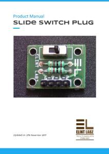
Updated on: 27th November 2017
Product Manual: LED Plug
Index Index
1
About Elint Labz
2
Introduction
3
Specification
3
Operating voltage: 5V
3
Variants
3
Supported cables:
4
Details
4
How to interface?
5
Example Codes
6
Code 1: Arduino
6
Code 2:8051
7
Elint Labz (www.elintlabz.in)
Page 1 of 6
Product Manual: LED Plug
About Elint Labz Elint Labz (usually abbreviated as EL) is an electronics design & development tools designer & manufacturer with headquarters in Bengaluru, India. We design, develop & manufacture development boards based on micro-controller & microprocessors, breakout boards for various sensors & actuators. Our domain & expertise is in the area of Electronics & Embedded Systems. Elint Labz was founded in 2014 however the actual operations started from 2015 when it became a full time subsidiary of Hogst Innovative Solutions Pvt. Ltd. & is presently a part of Ajaramara Group a conglomerate of various domains of industries, registered in India as Ajaramara Dynamics Pvt. Ltd. under Companies Act of 2013. As in the name company (Elint Labz) – Electronic intelligence (ELINT) is intelligence gathered by the use of electronic sensors, Laboratories (LABZ) are facilities that provides controlled conditions in which scientific or technological research, experiments and measurement may be performed. EL is an enterprise built to develop smart & intelligent electronics & EL is committed to help achieve electronics literacy in India. No matter the vision or skill level, our products and resources are designed to make electronics & programmable development hardware more accessible. Elint Labz as a platform helps developers & young engineers from prototyping to product development. We provide open source hardware solutions and small quantity manufacturing services using a design from manufacturing framework. We are a strong promoter of the maker movement in India, most of the manufacturing happens with support of our various Indian partners & couple of our collaboration partners who have manufacturing & sourcing facilities in Germany, Korea & Shenzhen. To know more visit the about us section on our website: http://elintlabz.in/about-us/ Elint Labz (HQ) 📮 #200 1st main Arekere MICO layout 2nd stage Bengaluru 560076 KA [Marked on Google Maps] ✆ +91 855 377 2525 📧
[email protected]
Elint Labz (www.elintlabz.in)
Page 2 of 6
Product Manual: LED Plug
Introduction This version of LED plug has an LED, SMD resistors and a transistor. In this plug CTBC 547B transistor is used, It has a small strip pasted on the back of the PCB , which can be used as indicator.This plug is available in different colors.
Specification
● Operating voltage: 5V ●
Size: 22mm x 22mm
Variants 1.
Diffused a. Red b. Yellow c. Green
2. Clear a. IR b. UV c. White d. Red e. Yellow Elint Labz (www.elintlabz.in)
Page 3 of 6
Product Manual: LED Plug
f.
Green
g. Blue
Supported cables: 1.
3-3 A
2. 4-3 A
Details This version of LED plug has a CTBC 547B transistor that is NPN bipolar transistor mounted on LED plug using which output can be obtained even with low input current, unlike other LED plug which require high input current. It has one SMD transistor and two resistors. The white strip pasted on the back of PCB can be used as indicator to specify the name , component code.....etc. It has a interfacing port with three pins named as G, V & D. Here G represents Ground , V represents VCC and D represents Data pin through which LED is controlled.
Elint Labz (www.elintlabz.in)
Page 4 of 6
Product Manual: LED Plug
How to interface? Use either of the supported interfacing cables to connect LED plug to the controller board. ● If 3-3 A cable is used then connect any end of the 3-3 A cable to the LED plug and another end to Controller board. Always ensure that black wire of the cable is connected to the G pin on both ends. ● If 4-3 A cable is used then 4 pin end of the cable is connected to the Controller board and 3 pin end of the cable must be connected to the LED plug. In the below given pictures one can see 4-3A cable is used to connect LED plug to the Pluguino Board. The data pin D of LED plug is connected to the GPIO pin 11 of the controller board. By controlling the voltage at the 11th GPIO pin of the controller board one can control the LED.
Elint Labz (www.elintlabz.in)
Page 5 of 6
Product Manual: LED Plug
Objective- This example demonstrates the working of an LED plug. Here the LED turns on with the delay of one second and turns off with the delay of one second.
Example Codes
Code 1: Arduino #define led_pin 11 void setup() { pinMode(led_pin,OUTPUT); pin }
// define 11th GPIO pin as OUTPUT
void loop() { digitalWrite(led_pin,HIGH);// making 11th pin HIGH so that LED turns ON
Elint Labz (www.elintlabz.in)
Page 6 of 6
Product Manual: LED Plug
delay(1000); // wait for 1 second delay so that LED stays ON for 1 second digitalWrite(led_pin,LOW); // making 11th pin LOW so that LED turns OFF delay(1000); // wait for 1 second delay so that LED stays OFF for 1 second }
Output video: https://youtu.be/dhYkOb9JinY
Code 2: 8051 // Program to blink an LED at Port pin P0.0 #include
// special function register declarations for 89s52 #include // prototype declarations for I/O functions sbit LED = P0^0; // defining pin P0^0 as LED void delay(void); //delay function prototype declaration void main (void) { LED = 0; // Make LED pin as Output while(1) //indefinite loop { LED = 0; // LED Off delay(); LED = 1; // LED ON delay(); } } void delay(void) { int j; int i; for(i=0;i<500;i++) { for(j=0;j<1000;j++) { } } }
Elint Labz (www.elintlabz.in)
Page 7 of 6
Product Manual: LED Plug
Output video:
Elint Labz (www.elintlabz.in)
Page 8 of 6
![Bi-colour LED Plug â [v2]](https://p.pdfkul.com/img/300x300/bi-colour-led-plug-a-v2_5accbf507f8b9ae9278b456b.jpg)

![THERMISTOR PLUG [v2]](https://p.pdfkul.com/img/300x300/thermistor-plug-v2_5b6c0a0a097c473e418b4567.jpg)


![Buzzer plug [v 1.1]](https://p.pdfkul.com/img/300x300/buzzer-plug-v-11_5b0169958ead0ef3158b456d.jpg)