Jigsaw Image Mosaics Junhwan Kim Dept. of Computer Science, Cornell University
Fabio Pellacini Program of Computer Graphics, Cornell University
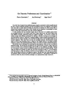
Figure 1: The Jigsaw Image Mosaic (JIM) algorithm takes as input an arbitrarily-shaped container image and a set of image tiles of arbitrary shape (left) and generates a mosaic (right); it then packs the container as compactly as possible with tiles of similar color to the container taken from the input set while optionally deforming them slightly to achieve a more visually-pleasing effect.
ABSTRACT This paper introduces a new kind of mosaic, called Jigsaw Image Mosaic (JIM), where image tiles of arbitrary shape are used to compose the final picture. The generation of a Jigsaw Image Mosaic is a solution to the following problem: given an arbitrarily-shaped container image and a set of arbitrarily-shaped image tiles, fill the container as compactly as possible with tiles of similar color to the container taken from the input set while optionally deforming them slightly to achieve a more visuallypleasing effect. We approach the problem by defining a mosaic as the tile configuration that minimizes a mosaicing energy function. We introduce a general energy-based framework for mosaicing problems that extends some of the existing algorithms such as Photomosaics and Simulated Decorative Mosaics. We also present a fast algorithm to solve the mosaicing problem at an acceptable computational cost. We demonstrate the use of our method by applying it to a wide range of container images and tiles. CR Categories: I.3.8 [Computer Graphics]: Application; I.3.5 [Computational Geometry and Object Modeling]: Geometric algorithms, languages, and systems; J.5 [Arts and Humanities]: Fine arts Keywords: Mosaics, Morphing, Optimization
1. INTRODUCTION Mosaics are a form of art in which a large image is formed by a collection of small images called tiles. Various mosaics can be created for an image depending on the choice of tiles and the
restriction in their placement. Tile mosaics, for example, are images made by cementing together uniformly colored polygonal tiles carefully positioned to emphasize edges in the composite picture; Simulated Decorative Mosaics [Hausner 2001] is an algorithm that can generate tile mosaics. Photomosaics [Silvers and Hawley 1997] are a different kind of mosaic where a collection of small images is arranged in a rectangular grid in such a way that when they are seen together from a distance they suggest a larger image. Finally, Arcimboldo, a Renaissance Italian painter, was the self-proclaimed inventor of a form of painting called the composite head where faces are painted, not in flesh, but with rendered clumps of vegetables and other materials slightly deformed to better match the human features [Strand 1999]. Inspired by Arcimboldo, we propose a new kind of mosaic where image tiles of arbitrary shape are used to compose the final arbitrarily-shaped picture. We called this new kind of mosaic Jigsaw Image Mosaic (JIM). Figure 1 illustrates the process of creating a JIM. Our algorithm takes as input a container image of arbitrary shape and a set of image tiles of arbitrary shape; it then packs the container as compactly as possible with tiles of similar color to the container taken from the input set while optionally deforming them slightly to achieve a more visually-pleasing effect. We can formally define the problem as follows: Problem (Jigsaw Image Mosaic): Given an arbitrarilyshaped container image and a set of arbitrarily-shaped tiles {Ti}, find a set of shapes {Sj} such that • the union over the Sj resembles the container image as closely as possible; and • each Sj is a translated and rotated copy of one of the Ti, possibly incorporating a small deformation. In order to compute a JIM, we introduce a general energy-based framework for mosaicing problems, where a mosaic is defined as the tile configuration that minimizes a weighted sum of energy terms. By changing the weights in the energy formulation, various kinds of mosaics can be generated. Our framework generalizes
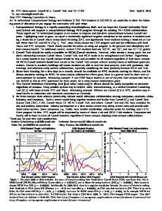
a) Input image
c) Jigsaw Image Mosaic (JIM)
d) Photomosaic
e) Simulated Decorative Mosaic
roughly 400 tiles from a database of 900 tiles
roughly 400 tiles from a database of 1100 photographs
roughly 400 tiles
b) JIM tile contours
Figure 2: Comparison of different mosaicing algorithms. some of the existing mosaicing techniques previously presented in the computer graphics literature such as Photomosaics [Silvers and Hawley 1997] and Simulated Decorative Mosaics [Hausner 2001]. A comparison of the images obtained by the three algorithms is presented in Figure 2. As with Photomosaics, our algorithm uses tiles containing smaller images. As in Simulated Decorative Mosaics, the Jigsaw Image Mosaics maintain important edges found in the container image; while the first algorithm does so by reorienting the tiles, our approach uses oriented tiles of the best-fitting shape as shown, for example, by the wedge-shaped tiles used in the sharp corners of the drops in Figure 2b and Figure 2c. The two algorithms use a segmentation of the original image in order to specify important edges. Our framework has three major advantages. First, a user can easily control the result image by changing the weights in the energy formulation. Second, we can introduce new mosaicing generation rules by introducing additional energy terms in the energy formulation. Finally, the mosaic generation and tile preparation is completely automatic requiring no user intervention. Since the Jigsaw Image Mosaic problem can be cast as an instance of an energy minimization problem, various algorithms such as simulated annealing could be employed to find a solution. Unfortunately, due to its high dimensional search space, most of the standard minimization techniques would demand too many resources to be run. This paper also presents a fast minimization algorithm tailored to solve the generalized mosaicing problem. We believe that the two major contributions of this paper are • an energy-based framework for the mosaicing problem which generalizes on known algorithms • an energy-minimization algorithm that solves the mosaicing problem at an acceptable computational cost Also, since our framework presents a general solution to ‘soft’ packing problems, where small deformations are acceptable, our framework can be applied to feature-based texture synthesis and to various instances of product manufacturing. Mosaics are just one application. The rest of this paper is organized as follows: Section 2 summarizes related work. In Section 3, we describe how to automatically prepare the required inputs. Sections 4 and 5 address the energy minimization framework of the mosaicing problem, and the basic algorithm for the framework respectively. Section 6 presents optimization techniques on top of the basic algorithm. We present our results in Section 7, and close with discussion and future work in Section 8.
2. RELATED WORK In the computer graphics literature, the works most closely related to our approach are the various mosaicing algorithms that can be categorized by the choice of tiles and the restriction on their placement. Photomosaics [Finkelstein and Range 1998; Silvers and Hawley 1997] are a collection of small images arranged in a rectangular grid in such a way that when they are viewed together from a distance they suggest a larger image (e.g. Figure 2d). For each rectangular block of pixels in the input image, the photomosaic algorithm searches a large database of tiles to find the one that most closely resembles the original block. The algorithm gives impressive results using only small resources, but unfortunately it is limited to square tiles on a rectangular grid. Simulated Decorative Mosaic [Hausner 2001] approaches the problem of aligning square tiles with varying orientations to preserve input image edges while maximizing the area covered by the colored tiles (e.g. Figure 2e). Our algorithm resembles that approach since it tries to maintain edges in the input image while maximizing coverage. Unfortunately, since we use tiles of different shapes, we cannot directly apply the Simulated Decorative Mosaic method for finding low-energy configurations. Our technique can compute the same results as these two algorithms, although its generality exacts a penalty in speed. Kaplan and Salesin [2000] presented a solution to the “Escherization" problem that finds a regular tiling using a closed figure that is as similar as possible to the original figure. Their work resembles our approach in that they slightly distort the original tile if necessary, but is different in that they seek regular tilings whereas we allow small gaps and overlaps. Haeberli [1990] randomly chose the tile positions, found the voronoi diagram of these positions, and filled each voronoi region with a color sampled from the underlying image. While his approach tessellates the main image using tiles of different shapes and completely arbitrary placements, the shapes are arbitrary and may not fit any of the given input tiles as required in our formulation. Another body of work related to our approach is the packing problem. The packing problem has been extensively studied in operations research and computational geometry with application to a broad spectrum of layout problems, such as for cloth, leather and glass. Since the packing problem is NP-hard [Milenkovic 1999], numerous heuristics have been developed: boundary matching, database driven layout, or leftmost placement policy (See [Dowsland and Dowsland 1995] for an extensive survey). Recent work of Milenkovic and his colleagues [1999] combined
Container
Trying 1st tile…
Trying 2nd tile…
Trying 3rd tile…
Trying 4th tile…
Trying 5th tile…
Legend
…high color energy Æ discard
… high gap energy Æ discard
…high overlap energy Æ discard
…high deformation energy Æ discard
…lowest energy Æ Accept
Container to be filled Container filled Tiles
Color mismatch
Gap region
Overlap region
Shape mismatch
Accepted tile
Figure 3: Illustration of mosaicing energy terms. computational geometry and mathematical programming for dense packing of polygons. Their approach applied to marker layout problems achieves packing efficiencies comparable to those of human experts. Our problem differs from the standard packing problem in that our aim is not to achieve maximumdensity packing, but to reach aesthetically pleasing packing. Inspired by Arcimboldo, we allow a small user-specified deformation of the tiles when necessary, which is not allowed in the standard packing problem formulation.
3. PREPARING INPUTS The JIM algorithm takes as input a container image of arbitrary shape and a set of tiles of arbitrary shape. The shape of tiles and container is represented by a polygon. Since we require a fairly high number of tiles, we need to be able to extract the shape of the tiles directly from the images themselves. We do so using active contours [Kass et al. 1987]. All of the 900 tiles used to generate the images in this paper are segmented completely automatically from clip art harvested from the Web. Active contours are also used to extract the container shape. Hausner [2001] showed the importance of preserving important edges in the input image when generating a mosaic. Following his approach, we segment the input image to generate a set of disjoint arbitrarily-shaped containers. Since we preserve the edge of each container, the final composite will preserve the important edges on the input image. Figure 2c shows this behavior. Within each part of the segmentation, the algorithm runs independently. By allowing the user to input arbitrary segmentations, we can also introduce edges that are not present in the input image, but are important to maintain for the user.
4. MOSAICING FRAMEWORK 4.1 Problem formalization In order to achieve user controllable and extensible framework, we cast the problem of generating a mosaic in an energy minimization framework. We define a “tile configuration” as a subset of the input tiles with repetition, along with their associated transformations (translation, rotation, deformation). We say that a tile configuration is a Jigsaw Image Mosaic when it minimizes the energy E defined as E = w C ⋅ E C + w G ⋅ E G + wO ⋅ E O + w D ⋅ E D . (1) The energy is a weighted sum of various terms. Figure 3 illustrates the behaviors of each of these energy terms in a simple example. The color energy term EC penalizes configurations that do not maintain the color of the input image. The gap energy term EG penalizes configurations that have too much empty space in the final image, called gap, while a big overlap between tiles gives large overlap energy EO. Finally, the deformation energy ED penalizes configurations where tiles are highly deformed. Inspired by Arcimboldo, we allow small deformations for each tile since we may not find a configuration where gaps or overlaps
are small enough to achieve a pleasing visual effect. This is more likely to happen for smaller tile databases. Since collecting a large number of tiles may be a long process, we believe that allowing the user to specify the amount of deformation necessary makes the algorithm more usable. In order to compute a Photomosaic in our formulation, we can simply restrict the tile database to rectangular tiles and set the weights for gap, overlap and deformation to infinity. To compute a Simulated Decorative Mosaic, we restrict the database to square tiles with uniform color, where the colors are chosen from the palette of the input image, and segment the container to preserve edges. We then set the deformation weight to infinity and a very high overlap weight (note that Simulated Decorative Mosaics results have sometimes very small overlaps [Hausner 2001]) and moderately high gap weight. We believe that our formulation is fairly intuitive to use, since the user can easily adjust the weights in the energy function to obtain different results. It is also easily extensible, since we can add new energy terms in order to introduce additional rules for image generation.
4.2 Energy terms evaluation
The color energy EC is estimated by taking the average of the L2 differences of the colors of the final image and the input container at random locations on the surface of the container. We evaluate this term for each tile separately to ensure a good sampling of the tile area. We evaluate gap EG and overlap EO energies using the spring energy formulation as originally employed to prevent bodies in resting contact from penetrating in rigid body simulations [Moore and Wilhelms 1988]. More specifically, each vertex of a tile is attached with a spring to the nearest edge of the other tiles or the container. If the signed distance d between the vertex and the anchor is positive, i.e. there is a gap between them, we add d2/2 to EG. On the other hand, if d is negative, i.e. the vertex penetrates the nearest edge, we add d2/2 to EO. The deformation energy ED is the sum of the deformation energies for each tile, which measures the difference in shape between the deformed tile and the original one. We evaluate ED in a similar way to the active contour model, given by 1 2 2 E D = ∑ik=1 ∫01α Di′′( s ) − Ti′′( s ) + β Di′′′( s ) − Ti′′(′ s ) ds , (2) 2 where Ti(s) and Di(s) are the original shape and the deformed shape of the i-th tile in the current solution, parameterized by s∈ [0,1]. The first term and the second term inside the integral measure the difference between the original tile and the deformed tile with respect to the stretching and flexing respectively, where α and β are sensitivity parameters. Among numerous shape metrics such as [Arkin et al. 1991], we choose the above one, since it provides good results in our case and it is easily integrated in our algorithm.
a) Initial container image
b) Tile contours after tile placement
Phase 1: Placing tiles
c) Tile contours after tile refinement
Phase 2: Refining tiles
d) Final Jigsaw Image Mosaic
Phase 3: Adjusting images
Figure 4: Jigsaw Image Mosaic algorithm phases.
5. BASIC MOSAICING ALGORITHM 5.1 Overview To efficiently compute a Jigsaw Image Mosaic, we propose an effective algorithm organized in three phases shown in Figure 4. In the first phase, we choose and roughly place the tiles, ignoring deformation. In the second phase, we refine the placement of each tile and deform them if necessary. Finally in the third phase, we assemble the final mosaic by placing each tile in its position and warping each image to its final deformed shape using the image warping technique presented in [Arad et al. 1994]. Intuitively, this three-phase approach works in our case because the deformations we allow are always much smaller than the smallest tile in the database.
5.2 Packing The first phase of the algorithm finds an approximately good configuration ignoring the deformation term, i.e. the configuration that minimizes the gap and overlaps in the image while maintaining the color, as measured by E = w C ⋅ E C + w G ⋅ E G + wO ⋅ E O . (3) To do so, we use a best first search [Russell and Norvig 1994]. Our algorithm places one tile at a time. For each new tile to place, we find a roughly suitable position in the container. We then search the database to determine which tile we should use, and determine the exact position and orientation of the tile in such a way that the tile is maximally aligned to the boundary of container, i.e., E in Equation 3 is minimized. This is a typical registration problem except that we register the tile to a part of the container, rather than the container itself. We will explain in more detail in Section 6 how to efficiently find a suitable spot using a centroidal voronoi diagram (CVD) [Lloyd 1982] and how to search the database using geometric hashing. After we place a tile, a new container is computed by subtracting the tile shape from the original container, as shown in Figure 5. The new container is used to place the next tile. We keep placing tiles until either the tiles completely fill out the container or we cannot find a suitable tile to fill a container. If this happens, we backtrack to the configuration that has minimal energy so far. Figure 6 illustrates the algorithm sequence. a
Initial container
Tile
b
Container with placed tile
5.3 Refinement Even after finding the best possible tile arrangement, too much gap or overlap may remain and be aesthetically displeasing, especially when using a small number of tiles. Sometimes we can obtain a better looking result by slightly deforming the tiles to reduce gaps and overlaps significantly, as long as the deformation does not alter the original tile too much. While this generally produces better looking images, the user has the option to define the amount or skip deformation. The refinement phase of our approach solves this issue by deforming the tiles obtained from the packing stage, while balancing between maintaining the original tile shape as closely as possible and minimizing the gap, overlap and color differences (i.e. minimizing the full energy equation). We compute the final configuration using a set of active contours [Kass et al. 1987] interacting with each other. Intuitively, each vertex of a contour is subject to forces that tend to maintain the contour’s original shape and to repulse two contours if they penetrate, or attract them if there is gap between them. The tile configuration that minimizes E in Equation 1 must satisfy the following euler equation: wC ⋅ ∇E C + wG ⋅ ∇E G + wO ⋅ ∇E O + w D ⋅ ∇E D = 0 . (4) ∇EC is close to zero for our case since the deformations are much smaller than the smallest tile. For each vertex, ∇EG=2d⋅n if the vertex is in a gap (0 otherwise), where n is the unit vector perpendicular to the nearest edge, d is the signed distance to the nearest edge. ∇EO=2d⋅n if the vertex penetrates another tile (0 otherwise). ∇EO makes the tile shrink if it is too big while ∇EG expands it if too small. The deformation term can be computed by differentiating Equation 2 for each vertex: (5) ∇E D = α (Di′′( s ) − Ti′′( s ) ) + β (Di′′′( s ) − Ti′′(′s ) ) . a
Container
c
Place 1st tile
b
Available Tiles
Cannot place next
Backtrack
c
Container for next iteration
Figure 5: Container update.
Try again 1st tile
Place next
Figure 6: Tile placement.
Done
Notice that Equation 5 is exactly the same energy formulation used for standard snakes but the ‘relaxed’ state is defined as the original tile shape rather than a simple straight line. Also, external forces are determined not by an image (as in the standard snake), but by gap and overlap between tiles and with the container. The solution to the above equation can still be found by solving the discrete system iteratively [Amini 1990]. Figure 7 shows the evolution from the original tiles to the deformed ones.
6. ALGORITHM OPTIMIZATIONS In the previous section, we presented the basic algorithm for tile placement. A naïve implementation would be too resource demanding so we present several optimization techniques in this section. The time complexity of the algorithm is roughly given by O (Vtile ⋅ N tile ⋅ Vcontainer ⋅ N tileInContainer ⋅ (1 + b )) . (6) where Vtile is the number of vertices per tile, Ntile is the number of tiles in the database, Vcontainer is the number of vertices in container, NtileInContainer is the number of tiles in the container, and b is the overhead due to branching in the search tree (backtracking). In the following subsections we will introduce optimization for each of the factors in Equation 6.
6.1 Placing a tile When placing a tile in a container of arbitrary shape, it would be prohibitive to try every possible location. As we mentioned before, we update the container after placing every tile. In order to reduce the branching overhead b, we try those locations that are most likely to make the container shape easier to fill after updating. Unfortunately this depends on which tile we place. Nevertheless, we can guess how the container would look after we put an “average” tile. A container will be easier to fill if it does not have a protrusion and is as convex as possible. Before placing a new tile, we construct a CVD, where each site has an area roughly equal to the average size of tiles (a similar technique has been previously used in [Hausner 2001]). We then select a random site among the ones that have the least number of neighbors, thus making the container as easy as possible to fill. Figure 8 shows the selection process. Notice that placing one tile at a time allows us to handle tiles with different sizes. Figure 2c, for instance, contains tiles that differ in size by 7 times.
6.2 Branch-and-bound with look-ahead Every time we cannot find a suitable tile to fill a container, we need to backtrack to the configuration that has minimal energy so far. To reduce this branching overhead b, we use a look-ahead technique [Russell and Norvig 1994]. When placing a new tile, we penalize tiles that will make it harder to fill the container in the next iteration. To do this we add a term to the energy formulation that takes into account how the container will look after tile placement. Thus, the energy in Equation 3 becomes: (7) E = wG ⋅ EG + wO ⋅ EO + wC ⋅ EC + wLA ⋅ E LA . The container shape term advocates for containers with a small area and short circumference, or (8) E LA = wA ⋅ area + (1 − wA ) ⋅ length 2 , where area is the container’s area, length is its boundary length, a) Initial contours
b) Intermediate contours
c) Converged contours
Legend CVD connected graph CVD cells Selected position: only two neighbors in the CVD graph
Figure 8: Selecting a tile position by CVD. and wA controls the weight of area in relation to the weight of length. Adding the container shape term in the energy evaluation prevents the algorithm from placing a tile that fits well but that leads to a harder-to-fill updated container.
6.3 Container cleanup After we place a tile in a container, we update the container by subtracting the tile from the container. However, the new container can be very jagged, or even have disjoint regions. If these fragments are shallower than the shallowest tile, we know it can never be filled with any existing tile. In that case, it is safe to separate those fragments and consider them as a gap. This cleanup process reduces the running time by cutting the number of vertices in the container Vcontainer. It also reduces the branching overhead b, since it prevents the algorithm from wasting time attempting to fill unpromising fragments of the container.
6.4 Geometric hashing Given a container and a location in the container, we need to try each tile in the database and their positions and orientations. Since the number of tiles is fairly high, a linear search would be prohibitive. To this end, we employ geometric hashing, a technique originally developed in computer vision for matching geometric features against a database of such features [Wolfson and Rigoutsos 97]. We use geometric hashing to select a few tiles that will suit to a particular position in the container. We then evaluate the energy term for them and pick the best fitting one. Intuitively we use geometric hashing as a pruning technique to reject bad tiles. In order to use geometric hashing, we will create a grid of squares in the plane in a preprocessing phase. Each square corresponds to a hash table entry. If a shape boundary crosses a square, we will record the tile ID and its orientation as an entry in the list attached to that hash table entry. In the preprocessing phase we place all tiles with all possible discrete orientations in the grid to build the hash table. Every time we need to place a new tile in a specific position in the container during the packing stage we register the container boundary segment to the hash table and access the hash table entries of the squares that the container passes through; for every entry found there, we cast a vote for the (tile ID, tile orientation) pair. We proceed to determine those entries that received more than a certain number of votes. Each such entry corresponds to a potential candidate. See Figure 9 for an illustration. This hashing technique reduces the time complexity of the algorithm from O(Ntile) to O(hgrid), where hgrid is the grid granularity. Legend
a) Bad tile: 15 votes
b) Good tile: 22 votes
Container contour Tile contour Container and tile contour overlap: cast a vote
Figure 7: Evolution of active contours.
Figure 9: Geometric hashing for the 3rd and 5th tile in Figure 3.
a) Base case
b) Lower color weight
c) Lower overlap weight
d) Tiles of finer scales
Figure 10: Mosaics for various parameters.
7. RESULTS We have used our algorithm to produce a number of Jigsaw Image Mosaics using various container images. The images contained in this paper were generated from a database of 900 tiles, some of which are from the Columbia Coil-100 dataset and Coolarchive.com. Size of the tiles varies by up to 8 times. It took about 10 minutes to 2 hours to generate the results. Figures 1 and 2 show that our algorithm faithfully reproduces colors and boundaries of letters and logos. Figure 10 shows three variations of the “J” mosaic in Figure 10a obtained by changing the parameters in the energy formulation. Figure 10b shows the result for a very low color weight. Figure 10c was computed allowing a large overlap between tiles. Figure 10d is a picture generated with tiles in different scales. These variations show how simply changing the weights in the energy function can generate different looking images that an artist can easily tweak. Figure 11 shows the result for a photograph of a panda. Given the container image and its segmentation, our algorithm reproduces the container image in a visually pleasing way. As in [Hausner 2001], we used the different scales of tiles to faithfully reproduce fine details of the containers, such as the mouth of the panda. Figure 12 shows a different example where the user draws additional edges to emphasize features of the picture, in this case the feathers of the parrot. As a result, our algorithm clearly reproduces the user-supplied features. Figure 13 shows an artistic picture of a kabuki, generated by preserving the edges of the original picture, but assigning different colors associated to each segment and a texture to the background.
8. CONCLUSIONS AND FUTURE WORK In this paper, we have presented a general energy-based framework for mosaicing problems that generalizes some of the existing algorithms. We also introduce a new kind of mosaic, the Jigsaw Image Mosaic (JIM), where tiles and container are arbitrarily-shaped images. Finally we presented an effective algorithm to quickly compute a JIM. Our method produces good results, and is general enough to be applied to other ‘soft’ packing problems such as texture synthesis and product manufacturing. This research suggests a number of directions for further study. Our current approach uses a search algorithm for packing. Even though it is effective because of the elaborate use of look-ahead technique and other optimizations, it is difficult to formally prove bounds on the energy of the final configuration. Approaches based on mathematical programming or computational geometry as in [Milenkovic and Daniels 1999] could be fruitful. Our framework could also be extended to 3D mosaic, where the container is a 3D object and the tiles can be 2D to fill out the surface of the container, or 3D to fill out the container itself.
9. ACKNOWLEDGEMENTS We would like to thank Eva Tardos, Klara Kedem, Paul Chew, Shimon Edelman, James E. Cutting, Vladimir Kolmogorov, and Amy Gale for their insights and comments and to Ramin Zabih and Donald P. Greenberg for their encouragement. Peggy Anderson, Parag Tole, and Steven Westin carefully read the manuscripts. We would also like to thank Alejo Hausner for providing us his software and to the anonymous reviewers for their constructive critiques. Some of the tiles in Figure 2d were obtained from the MIT VisTex web page (Copyright © 1995 MIT. All rights reserved). Junhwan Kim was supported by NSF grants IIS-9900115 and CCR0113371 and a grant from Microsoft Research, while Fabio Pellacini was supported by NSF Science and Technology Center for Computer Graphics and Scientific Visualization (ASC-8920219).
10. BIBLIOGRAPHY AMINI, A. A. 1990. Using Dynamic Programming for Solving Variational Problems in Vision. IEEE Trans. on PAMI, Vol. 12, no 9, pp. 855-867, Sept. 1990. ARAD, N., DYN, N., REISFELD, D., AND YESHURUN, Y. 1994. Image warping by Radial Basis Functions: Application to Facial Expressions. Computer Vision, Graphics, and Image Processing. GMIP, 56 (2), 161--172, 1994. ARKIN, M., CHEW, P., HUTTENLOCHER, D. P., KADEM, K., AND MITCHELL, J.S.B. 1991. An Efficiently Computable Metric for Comparing Polygonal Shapes. IEEE Trans. on PAMI, Vol. 13, No. 3, 209-216, Mar. 1991. DOWSLAND, K. A. AND DOWSLAND, W. B. 1992. Packing Problems. European Journal of Operational Research, 56:2 - 14, 1992. DOWSLAND, K. A. AND DOWSLAND, W. B. 1995. Solution Approaches to Irregular Nesting Problems. European Journal of Operational Research, 84:506--521, 1995. FINKELSTEIN, A. AND RANGE, M. 1998. Image Mosaics. In Roger D. Hersch, Jacques André, and Heather Brown, Ed., Artistic Imaging and Digital Typography, LNCS, No. 1375, Heidelberg: Springer-Verlag 1998. HAEBERLI, P. 1990. Paint by Numbers. In Computer Graphics (Proceedings of ACM SIGGRAPH 90), 24(4), ACM, 207-214. HAUSNER, A. 2001. Simulating Decorative Mosaics. In Proceedings of ACM SIGGRAPH 2001, ACM Press / ACM SIGGRAPH, New York, E. Fiume, Ed., Computer Graphics Proceedings, Annual Conference Series, ACM, 573-580. KAPLAN, C.S. AND SALESIN, D.H. 2000. Escherization. In Proceedings of ACM SIGGRAPH 2000, ACM Press / ACM SIGGRAPH, New York, K. Akeley, Ed., Computer Graphics Proceedings, Annual Conference Series, ACM, 499-510. KASS, M., WITKIN, A., AND TERZOPOULOS, D. 1987. Snakes: Active Contour Models, International Journal of Computer Vision, 1:321--331, 1987. LLOYD, S. 1982. Least Square Quantization in PCM. IEEE Transactions on Information Theory, 28(1982): 129-137. MILENKOVIC, V.J. 1999. Rotational Polygon Containment and Minimum Enclosure using only Robust 2D Constructions, Computational Geometry, 13(1):3-19, 1999. MILENKOVIC, V. J. AND DANIELS, K. 1999. Translational Polygon Containment and Minimal Enclosure using Mathematical Programming. Transactions in Operational Research, 6:525-554, 1999. MOORE, M. P. AND WILHELMS, J. 1988. Collision Detection and Response for Computer Animation, In Computer Graphics (Proceedings of ACM SIGGRAPH 88), 22(4), ACM, 289--298. RUSSELL, S AND NORVIG, P. 1994. Artificial Intelligence: A Modern Approach, Prentice Hall, 1994. SILVERS, R AND HAWLEY, M. 1997. Photomosaics, New York: Henry Holt, 1997. STRAND, C. 1999. Hello, Fruit Face! : The Paintings of Guiseppe Arcimboldo, Prestel, 1999. WOLFSON, H. J. AND RIGOUTSOS, I. 1997. Geometric Hashing: An Overview. IEEE Computational Science and Engineering, Vol. 4, No. 4, pp. 10-21.
Figure 11: Panda mosaic with 1367 tiles. Inset: segmentation. Different scales of tiles are used to faithfully reproduce the fine details of the mouth of the panda.
Figure 12: Parrot mosaic with 1812 tiles. Inset: segmentation. Additional edges are introduced to reproduce the parrot feathers and add leaves.
Figure 13: Kabuki mosaic with 4200 tiles. Inset: segmentation. Colors are arbitrarily assigned for each segment.