Electrochemical and Solid-State Letters, 9 共8兲 G272-G275 共2006兲
G272
1099-0062/2006/9共8兲/G272/4/$20.00 © The Electrochemical Society
Influence of TaN Gate Electrode Microstructure on Its Dry Etch Properties D. Shamiryan,z V. Paraschiv, Z. Tőkei, S. Beckx, and W. Boullart IMEC, Leuven 3001, Belgium The etch properties of physical vapor deposited TaN used as a metal gate electrode have been found to be dependent on its crystalline microstructure. As found by X-ray diffraction, the initially amorphous TaN crystallizes at temperatures above 500°C. The crystallization results in lower resistivity 共decreased by 13%兲, and lower etch rate in BCl3 plasma 共decreased by 24%兲. The different crystalline microstructure can manifest itself in different etch results when the same etch process is applied for gate stacks that contain the same TaN but were subjected to different thermal budget. © 2006 The Electrochemical Society. 关DOI: 10.1149/1.2208010兴 All rights reserved. Manuscript submitted January 27, 2006; revised manuscript received April 14, 2006. Available electronically June 6, 2006.
The trend toward higher density devices brought new challenges that might be solved by introduction of new materials. Replacement of conventional poly-Si gate by metal gates is driven by issues associated with poly-Si such as gate depletion and carrier mobility decrease, if conventional SiO2 gate dielectric is replaced by the new high-k materials. Refractory metal nitrides such as tantalum nitride 共TaN兲, hafnium nitride 共HfN兲, or titanium nitride 共TiN兲 are considered potential candidates for metal gate applications1,2 being more chemically and thermally stable as compared to pure metals and binary alloys. Tantalum nitride is one possible candidate as metal gate electrode3 because it allows, for example, tuning of the work function by doping.4 One of the advantages of TaN is the fact that it is already used in semiconductor manufacturing, particularly in back-end-of-line as a diffusion barrier in Cu-based metallization schemes.5 In particular, because the crystallinity of the barrier has a profound effect on its diffusion blocking properties, the crystallization of both Ta and TaN was extensively studied. X-ray diffraction 共XRD兲 showed that Ta and TaN can be polycrystalline already as deposited6,7 or crystallize upon anneal at temperatures of 450–550°C.8,9 It was also observed that with addition of nitrogen to tantalum, the film crystallization is less pronounced.10,11 TaN can be amorphized by exposure to O2 or N2 plasma.8 The crystalline structure of TaN manifest itself on XRD spectra in the range of 30–40° 2 where peaks of TaN 共110兲, TaN 共200兲, TaN 共111兲 andTa2N are present. However, none of the papers dealing with crystalline properties of TaN refers to its etch properties since dry etch is not required for diffusion barrier manufacturing. The dry etch of TaN became necessary as this material started to be used as a gate electrode for the front-end-of-line applications. Halogens are used for TaN etch as Ta forms volatile compounds: TaF5 共boiling point 229.2°C兲, TaCl5 共b.p. 239.35°C兲 and TaBr5 共b.p. 349°C兲.12 There are number of reports of etching TaN with SF6,13 Cl2 /SF6 /Ar,14 Cl2,15 SiCl4-NF316 and Cl2 /O2 or HBr/O217 chemistries. These studies are mostly dealing with etch rates, plasma composition during etch, and post-etch surface characterization. None of the aforementioned papers described the crystallinity of the TaN films and its influence on the dry etch process. We selected chlorine among other halogens to etch TaN. Flourine-based chemistries have poor selectivity over silicon oxide hard mask that is used for gate patterning in our process flow, while HBr has significantly lower etch rate compared to chlorine.17 It should be pointed out that chlorine is sensitive to the crystallographic orientation of the etched material, this is the case, for example, for etching of silicon with molecular chlorine.18 However, in the case of Si this dependence can be easily overcome by application of bias 共thus providing ion bombardment兲 during plasma etch-
z
E-mail:
[email protected]
ing and the crystalline structure was not reported to play a key role in silicon gate patterning 共e.g. amorphous or polycrystalline Si gates exhibit almost no difference in etch behavior兲. However, the crystallographic dependence of chlorine plasma etch is reported to be more pronounced for metals, in particular for copper etching with chlorine.19 In this work we show that influence of the TaN crystalline structure on its etch behavior in a chlorine-based plasma is not negligible and should be taken into account during development of the metal gate patterning. The first obvious choice for TaN etch is a Cl2-based plasma that has reasonable selectivity toward most of the new high-k dielectric candidates. However, Cl2 plasma has a considerable disadvantage, it has no selectivity toward Si substrates because Si is easily etched by it. Also we should mention that TaN easily forms Ta2O5 in contact with any oxygen source 共e.g., air exposure after the deposition兲 and the oxide cannot be etched by Cl2. An oxide removing breakthrough step is needed before switching to Cl2. High selectivity of Cl2 toward metal oxides turns out to be a disadvantage in this case. One possible candidate for metal gate etch is a BCl3-based plasma. It has at least two advantages: high selectivity toward Si substrate 共due to Si surface passivation by B兲,20 and capability to etch metal oxides 共O is easily removed as volatile BOCl compound兲 that eliminates the need of a breakthrough step. Inherently all these benefits makes BCl3 a promising candidate also for high-k removal. BCl3 might be also combined with Cl2 to achieve required etch properties. In this paper we are analyzing the influence of the TaN microstructure 共determined by exposure to elevated temperatures during different integration steps兲 on its etch characteristics. Experimental Two types of test material were used: blanket TaN wafers and patterned wafers containing TaN in the gate stack 共200 mm Si wafers were used兲. For the experiments carried out on blanket wafers, a physical vapor deposition 共PVD兲 TaN layer of 70 nm thick was deposited on 50 nm of oxide. After the deposition some of the blanket TaN wafers were subjected to anneal in nitrogen ambient. Two types of patterned wafers were used referred to as TiN/TaN and poly/TiN/TaN stacks. The stack descriptions are shown in Table
Table I. Composition of the TiN/TaN and poly/TiN/TaN stacks. Layer thickness 共nm兲 Layer in the stack 共top to bottom兲 193 nm resist Organic BARC Oxide hard mask Poly Si 共dep at 650°C兲 PVD TiN 共dep at 350°C兲 PVD TaN ALD HfO2
TiN/TaN
Poly/TiN/TaN
200 55 120 N/A 70 15 3
200 55 60 100 10 15 3
Electrochemical and Solid-State Letters, 9 共8兲 G272-G275 共2006兲
G273
Table II. Specific resistivity of the studied TaN before and after anneal. Specific resistivity, ⍀·cm
Material
205 178
As deposited TaN TaN annealed at 650°C
= Rsh · d
关1兴
where Rsh is the sheet resistance and d its thickness measured by cross-sectional scanning electron microscope 共X-SEM兲. The thickness can be determined using an equation obtained by transformation of Eq. 1 to d=
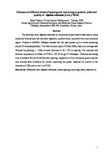
Figure 1. XRD spectra of TaN annealed at various temperature in N2 ambient.
Rsh
关2兴
Note that Eq. 2 is valid only if is constant across the film thickness. To verify the validity of Eq. 2 the film thickness after etch was measured by X-SEM as well as calculated from the sheet resistance measurement; the two values were found in good agreement. Results and Discussion
I. It is very important to note that for both stacks the TaN is encapsulated by the same materials, HfO2 at the bottom and TiN at the top. However, the temperature budget of the two stacks is substantially different: the highest temperature seen by the TiN/TaN stack is 350°C 共during the TiN deposition兲 while the highest temperature seen by the poly/TiN/TaN stack is 650°C 共during the poly-Si deposition兲. The plasma etch was performed in a LAM Versys2300 etch chamber configured for 200 mm wafers. This is a transformercoupled plasma 共TCP兲 reactor that allows separate control of the plasma power and substrate bias. The etch of TaN in the patterned stacks was performed in two steps: main etch 共ME兲 using BCl3 /O2 chemistry 共small amount 3 to 5% of O2 was added for TaN profile control兲 followed by over etch 共OE兲 by pure BCl3 chemistry. The blanket TaN wafers were inspected by XRD after various anneals to determine temperature influence on TaN crystalline structure. Etch rates were determined using sheet resistance measurements. First, the specific resistivity of TaN was determined using the formula
It was found that after deposition TaN is amorphous, as no crystalline peaks were found in the XRD spectrum. However, upon anneal TaN crystallizes exhibiting a peak at about 38–39° as it is shown in Fig. 1 that corresponds to reported TaN peaks.6-11 One can see that the crystallization process occurs at temperatures as low as 500°C. After the crystallization, TaN specific resistivity calculated using Eq. 1 decreases. The sheet resistance measured by a four-point probe and thickness measured by X-SEM. While no decrease in thickness was observed by X-SEM, the sheet resistance decreased by about 20% upon anneal at 650°C 共well above the crystallization temperature兲 as shown in Table II. The observed decrease can be attributed to the known fact of the lower resistivity of amorphous phase of a material as compared to a polycrystalline one. Exposure of the TaN layer at temperatures above its crystallization point influences its etch behavior, Fig. 2, where the amount of TaN removed is plotted vs etch time. The as-deposited TaN has shown an induction period of ⬃15 min. The delay might be attributed to the oxidation of TaN surface in the atmosphere and Ta2O5 formation which, apparently, has lower etch rate. The annealed TaN shows no delay and its removal rate is linear from the very beginning. One possible explanation might be that native Ta2O5 is converted to TaN in the N2 annealing ambient. Also, we have to count on the fact that the oxidation rate of the polycrystalline TaN might be lower than that of the amorphous TaN. These speculations, however, have to be confirmed by further studies of the TaN surface composition, e.g., by XPS. It is well known that crystalline phase of a material is usually etched slower than the amorphous one, and as expected, the asdeposited 共amorphous兲 TaN was etched faster than the annealed one 共polycrystalline兲. The etch rates 共determined from the slopes兲 are shown in Table III. Changing TaN crystallinity during device fabrication, from amorphous to crystalline is reflected in different etch results of patterned stacks containing TaN. In both stacks studied in this work the TaN layer is sandwiched between the same materials: HfO2 at the bottom and TiN at the top. Therefore, the main parameter that can influence TaN properties is the different thermal budget
Table III. Etch rate of as deposited and annealed TaN in BCl3 plasma. Figure 2. Amount of removed TaN as a function of etch time. Plasma etch parameters are: BCl3 100 sccm, TCP power 450 W, substrate bias 55 V, pressure 5 mT.
Material As deposited TaN TaN annealed at 650°C
Etch rate, nm/min 52.2 39.6
G274
Electrochemical and Solid-State Letters, 9 共8兲 G272-G275 共2006兲
Figure 3. Tilted X-SEMs after etching of TaN with the same etch recipe in TiN/TaN 共a兲 and poly/TiN/TaN 共b兲 stacks: ME: BCl3 95 sccm, O2 5 sccm, TCP power 450 W, substrate bias 30 V, pressure 5 mT, time 12 s; OE: the same recipe without O2 for 15 s.
Figure 5. Cross-sectional SEMs 共full 关a兴 and tilted 关b兴兲 of poly/TiN/TaN stack after TaN etch with the modified recipe: ME: BCl3 97 sccm, O2 3 sccm, TCP power 450 W, substrate bias 55 V, pressure 5 mT, time 20 s; OE: the same as ME but with pure BCl3 共no O2兲 for 15 s at 30 V.
Figure 4. X-SEM micrographs after etching of TiN/TaN 共a兲 and poly/TiN/TaN 共b兲 stacks with the same two-step TaN etch recipe as described in the caption of Fig. 3.
seen by these layers. In the case of TiN/TaN stack the highest temperature to which TaN was exposed is 350°C, that is not enough to crystallize TaN as can be seen from Fig. 1. The poly/TiN/TaN stack, however, is exposed to temperatures as high as 650°C during poly-Si deposition. According to the results presented in Fig. 1, this temperature is high enough to induce TaN crystallization. Therefore, we might expect different etch properties of TaN layer in the poly/TiN/TaN stack as compared to the TiN/TaN stack. Indeed, the etch recipe developed to pattern TaN in the TiN/TaN stack produces different results when it is applied to etch TaN in poly/TiN/TaN stack. Figures 3 and 4 show SEMs of the patterned lines for TiN/TaN and poly/TiN/TaN stacks, respectively. Tilted view shows that while the TiN/TaN stack is smoothly etched 共Fig. 3a兲 a lot of TaN residues are still present in poly/TiN/TaN stack. Most likely these are a reflection of the granular structure of TaN, 共Fig. 3b兲. The cross-sectional view of a TiN/TaN gate stack shows straight TaN profile 共Fig. 4a兲 while in the poly/TiN/TaN stack TaN shows substantial “footing” 共Fig. 4b兲. We might speculate that the polycrystalline structure of the annealed TaN in the poly/TiN/TaN stack is responsible for the observed etch results, especially when the recipe contains O2and is operating at low bias. To overcome the encountered problems in the poly/TiN/TaN stack the TaN etch recipe had to be modified: substrate bias was increased from 30 to 55 V to make the plasma less selective to different crystallites, O2 content was decreased from 5 to 3% to get rid of the footing and etch time was increased to compensate the lower etch rate. These changes allowed us to clear all TaN, selectively to the substrate, with an acceptable gate profile for the poly/TiN/TaN stack as shown in Fig. 5.
Electrochemical and Solid-State Letters, 9 共8兲 G272-G275 共2006兲 Conclusions PVD TaN used for metal gate application changes its properties upon anneal. Exposure to the temperatures higher than 500°C results in crystallization of amorphous TaN. As a consequence the TaN has 24% lower etch rate in BCl3 plasma, 13% lower resistivity and exhibits micro-non-uniformity during the etching, attributed mainly to the crystalline structure. Attention should be paid to the thermal budget after TaN deposition since amorphous and polycrystalline TaN require different etch recipes. Acknowledgments We thank Mikhail Baklanov for fruitful discussions and the IMEC pilot line for preparing the test wafers. References 1. D.-G. Park, Z. J. Luo, N. Eldeman, W. Zhu, P. Nguyen, K. Wong, C. Cabral, P. Jamison, B. H. Lee, A. Chou, M. Chudzik, J. Bruley, O. Gluschenkov, P. Ronsheim, A. Chakravarti, R. Mitchell, V. Ku, H. Kim, E. Duch, P. Kozlowski, C. D’Emic, V. Narayanan, A. Steegen, R. Wise, R. Jammy, R. Rengarajan, H. Ng, A. Sekiguchi, and C. H. Wann, in Proceedings of the VLSI Symposium, p. 186 共2004兲. 2. H. Y. Yu, J. F. Kang, J. D. Chen, C. Ren, Y. T. Hou, S. J. Whang, M.-F. Li, D. S. H. Chan, K. L. Bera, C. H. Tung, A. Du, and D.-L. Kwong, Tech. Dig. - Int. Electron Devices Meet., 2003, 99. 3. X. F. Yu, C. X. Zhu, M. F. Li, A. Chin, M. B. Yu, A. Y. Du, and D. L. Kwong,
G275
IEEE Electron Device Lett., 25, 501 共2004兲. 4. C. Ren, D. S. H. Chan, X. P. Wang, B. B. Faizhal, M.-F. Li, Y.-C. Yeo, A. D. Trigg, A. Agarwal, N. Balasubramanian, J. S. Pan, P. C. Lim, A. C. H. Huan, and D.-L. Kwong, Appl. Phys. Lett., 87, 073506 共2005兲. 5. K. Holloway, P. M. Fryer, C. Cabral, Jr., J. M. E. Harper, P. J. Bailey, and K. H. Kelleher, J. Appl. Phys., 71, 5433 共1992兲. 6. M. T. Wang, Y. C. Lin, and M. C. Chen, J. Electrochem. Soc., 145, 2538 共1998兲. 7. M. Takeyama, A. Noya, T. Sase, A. Ohta, and K. Sasaki, J. Vac. Sci. Technol. B, 14, 674 共1996兲. 8. K.-L. Ou, W.-F. Wu, C.-P. Chou, S.-Y. Chiou, and C.-C. Wu, J. Vac. Sci. Technol. B, 20, 2145 共2002兲. 9. G. S. Chen, S. T. Chen, L.-C. Yang, and P. Y. Lee, J. Vac. Sci. Technol. A, 18, 720 共2000兲. 10. S. W. Hong, C.-H. Shin, and J.-W. Park, J. Electrochem. Soc., 149, G85 共2002兲. 11. K.-H Min, K.-C. Chun, and K.-B. Kim. J. Vac. Sci. Technol. B, 14, 3263 共1996兲. 12. D. R. Lide, CRC Handbook of Cchemistry and Physics, 85th ed., CRC Press, Boca Raton, FL 共2004兲. 13. B. W. Smith, C. Fonseca, L. Zavyalova, Z. Alam, and A. Bourov, J. Vac. Sci. Technol. B, 15, 2259 共1997兲. 14. M. H. Shin, S.-W. Na, N.-E. Lee, T. K. Oh, J. Kim, T. Lee, and J. Ahn, Jpn. J. Appl. Phys., Part 1, 44, 5811 共2005兲. 15. K. B. Jung, E. S. Lambers, J. R. Childress, and S. J. Pearton, J. Electrochem. Soc., 145, 4025 共1998兲. 16. H. Shimada and K. Maruyama, Jpn. J. Appl. Phys., Part 1, 43, 1768 共2004兲. 17. W. S. Hwang, J. Chen, and W. J. Yoo, J. Vac. Sci. Technol. A, 23, 964 共2005兲. 18. R. J. Madix and J. A. Schwarz, Surf. Sci., 24, 264 共1971兲. 19. S. Park, T. N. Rhodin, and L. C. Rathbun, J. Vac. Sci. Technol. A, 4, 168 共1986兲. 20. L. Sha and J. P Chang, J. Vac. Sci. Technol. A, 22, 88 共2004兲.