INFLUENCE OF INCIDENT ANGLE ON LASER DRILLING Paper (#1205)
Matthieu Schneider, Laurent Berthe, Maryse Muller, Rémy Fabbro Laboratoire pour l’Application des Lasers de Puissance (UPR CNRS 1578) 16 bis Avenue Prieur de la Côte d’Or 94114 Arcueil France
Abstract To drill sub-millimeter holes, laser percussion drilling has been a well-established industrial process for tens years. However, physical understanding is still quiet difficult because laser source can be instable with low pulse reproducibility, correlation between experimental parameters and hole morphology are not clearly identified. This paper deals with the study of hole morphology in function of peak power and incident angle. Holes are drilled with a millisecond laser source, their morphologic characteristics are essentially diameter, recast layer thickness, and depth. Results are based on a new and very fast hole analysis method (called DODO for Direct Observation of Drilled hOle). The influence on hole morphology of incident angle and peak power in a string of pulse are shown (drilled depth, diameter, recast layer thickness,…). Results reveals incident angle is not a determinant parameter in percussion drilling. The influence of peak power is fitted in the string pulse to eliminate the recast layer cracking. It comes from a solidification of a melt layer on a previous recast layer. To eliminate it from the hole, it is essential to melt the previous recast layer with higher peak power pulse than the previous one. With this drilling method, hole drilled has only one single recast layer at the end of the drilling, so hole cannot present some decohesion. Keywords : laser drilling, percussionnal regime, hole analysis, DODO method, recast layer cracking Introduction Laser with pulse duration of millisecond are useful tool to drill holes whose diameter is sub-millimetric (0.3 to 0.5 mm) and depth can reach up to 20 mm. Usual configuration is the percussion regime. It consists in irradiating the target with a static laser until the hole breakthrough. According to the depth, multi-pulse laser can be performed. However, poor quality as decohesion is often produced along the wall of holes due to the accumulation of recast layers generated by each pulse [1, 2].
Recently, we have demonstrated that specific chain of laser pulses can suppress co-lateral effects induced by multi-pulse laser. For example, second high intensity pulse can suppress affected zone produced by a first low intensity pulse. Following these results, this paper presents the case of multi-pulse laser drilling with three pulses. Besides, paper extends the study for these drilling as function of incident angle (0°, 60°, 70°) more representative of applications in aeronautic aircraft engine [3]. Drilling with high incident angle opposes two physical effects. On one hand, the Fresnel absorbtivity decreases for highest incident angle. The target absorption is generally considered solid or liquid whose the temperature is close to the fusion one Absorptivity is quiet well-known in function of temperature until the fusion temperature. However, one the other hand, the surface temperature during drilling is higher than the vaporization one. For this higher temperature the absorptivity, this time, increases and is not known. So, showing the correlation degree between incident angle and hole morphology allows to deduce if this experimental parameter is determinant for physical understanding and quality of the drilling. The first part presents experimental set ups including HL201P laser and ultra fast camera. Direct hole analysis method (called DODO for Direct Observation of Drilled hOle) is also used for morphology analysis of holes. The second part, presents and discusses results concerning video acquisition and hole morphology as function of laser parameters. Besides, specific discussions on the vapor pressure in the hole, revealed by the presence of a stationary shock wave are presented. Experimental Set Up Source characteristic & analysis method The laser used for this study is the HL201P from TRUMPF (LALP’ laser facility). The laser pulse duration is in the range from 0.1 to 1 ms and the peak
Fig 1: video acquisition of laser drilling with gas with 45° incident angle. power from 1 to 18 kW. The laser beam diameter in the focal plan, equals to 330 µm. Previous article [4, 5] demonstrate that the laser source characterization has a very good pulse reproducibility (statistical dispersions are below to 1 %), a top hat distribution and a numerical aperture equals to 0.03 radian. In the range of its parameters, this laser allows any configuration of string of pulse (intensity, pulse duration, frequency). Previous papers [1, 2] described a new analysis method called DODO for Direct Observation of Drilled hole. It consists in locating the drilling axis in the analysis plane. To do it, two polished samples are tightly assembly. Holes are drilled in such manner that their axis are in the interface plane of samples. After drilling, the samples are easily separated and reveal half hole shape on each one. Consequently, DODO ensures the observation analysis plane and so measurements associated to morphology analysis (depth (E), diameter (D), conicity,….). Camera Set Up Fig 1 shows a video image sequence records with a 100 000 frames per second speed camera (Photron, Ultima APX RS). For this video acquisition, no external lighting is used because the drilling process is very shining. The sequence presented begins 10 µs before the first luminosity, and stop at 550µs The target is titled of 45°.
Experimental procedures In experiments, drillings are made with laser focused on the target surface for one or several incidence angles (θ) with different peak powers (Ppeak). The pulse duration is 1 ms. An argon shield gas (Psurface<1bar) is used to only protect optics. The hole depth (E) is measured one the laser axe and The hole diameter (D) is measured near the entrance. Results & Discussion Hydrodynamic of the drilling Results Fig 1 shows a video acquisition of laser drilling with gas at 105 frames per second with 45° incident angle. The scale on each image is the millimeter. The first images line is recorded every 10 µs and the second one every 50 µs. At the beginning, vapor expansion is normal to the target surface. Until 500 µs the flow becomes parallel to the laser axis, when the drilling penetrates in the target. Clearly, the assistant gas used does not deflect the vapor flow. As, the recoil pressure is responsible of the drilling phenomena [6], the axe of expansion vapor is also the drilling axe. Consequently, the sequence of drilling can be separated in two parts. First at the beginning, the drilling axe is normal to the target surface. Second,
when the laser penetrates the target, the drilling is parallel to the laser axe. The melt pool start to be ejected from 50 µs. its direction is parallel to the drilling axe. At the beginning it is normal to the target surface and from 500 µs until the end of the drilling the direction of the ejection is parallel to the laser axe. Scories go up straight toward the optics. The assistant gas used, slows down the scories and protects the optics from them.
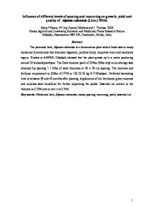
Fig 2: A schematic of a standing shock wave with the mach number (M) and the pressure (P) in each region.
Discussion At the beginning of the drilling sequence, the irradiated area target temperature goes to the vaporization temperature. Then the vapor pressure is above atmospheric pressure [7]. The vapor pressure increases with longer irradiation time. As shown in previous paper [8, 9], the flow becomes supersonic and the jet is very directional. With the approximation of an isentropic flow [10, 11] for a monoatomic gas, the vapor expansion is supersonic when the pressure inside the hole (Phole) is 2.05 bars, see Tab 1. Criteria of supersonic Monoatomic jet
Phole >2,05 Pamb
Monoatomic
Diatomic
Phole >2,91 Pamb
Phole >2,80 Pamb
γ
Phole 1−γ 2 γ −1 >1− Pamb 2γ
Tab 2: Phole is static pressure in the hole, Pamb is the ambient pressure, γ is the adiabatic constant. Tab 2 shows that a Mach Shock Disk (MSD) can appear in the flow when the pressure inside the hole is above to 2.91 bars.
Phole >1,89 Pamb
So, as long as MSD is visible from 50 µs, the pressure inside the hole reaches or is higher than 2.91 bars.
Tab 1: Phole is static pressure in the hole, Pamb is the ambient pressure, γ is the adiabatic constant. Through a shock wave, see Fig 2, the pressure increases and the Mach number decreases [9, 10] by the relation:
P2 2γM 12 −γ +1 > = X >1 γ +1 P1 γ +1 M 22 = 1 γ −1+ <1 2γ X
Criteria of shock wave existence
Diatomic
γ
Phole 2 γ −1 > Pamb 1+γ
With equation 1, 2 and 3, a criteria of shock wave existence can be deduce, see Tab 2.
(1) (2)
The difference in the hydrodynamic description between laser drilling with normal incidence and with 45° is visible from the beginning of the drilling until 500 µs, when the drilling axe becomes along the laser axis, see article [9]. For a laser drilling with a normal incidence the vapor expansion is vertical from the beginning. Whereas the vapor expansion starts normally to the target surface for a drilling with 45° incident angle. Morphology of hole drilled Results
In this analogy, P2 is the ambient pressure (Pamb). M1 is the Mach number at the hole entrance, and is related to the ration between Phole and Pamb by: γ −1 Phole γ 2 M hole = 1 − 1−γ Pamb
(3)
Tab 3 presents typical hole profiles drilled at 10kW peak power (Ppeak), 1ms pulse duration (τ),with multi pulse and two incident angles (θ) 0 and 60°. The incident angle is reminded on Fig 2.
The depths drilled (D) are 2.3, 4.3, and 6.4 mm for 1, 2 and 3 pulses respectively. The diameter is constant at 0.64 mm. Ppeak (kW) τ(ms) N θ (°)
5-16
0
1 2 60
70
Fig 3: Schematic representation of the incident angle. Ppeak (kW) τ (ms) N θ (°)
10
10-10
10-1010
10
10-10
1
2 60
10-1010
1 1
2 0
3
3 E(mm) 4.4 4.5 4.5 D(mm) 0.52 0.48 0.55 a) b) c) Tab 4: Hole profiles obtained with three incident angles at different peak power by pulse. Hole profile on Tab 3.d), e) and f) are drilled respectively with 1, 2 and 3 pulse at 60° incident angle. Hole profiles looks like those drilled with normal incident angle. Tab 4 and 5 present some hole profiles drilled with multi-pulses at different peak power. Holes profiles presented in Tab 4 are drilled with two pulses at respectively 5 then 16 kW for different incident angles. Tab 5 present three hole profiles drilled with 3 pulses at respectively 5 then 10 then 18 kW for the same incident angles.
E(mm) 2.3 4.3 6.4 2.1 4.5 6.5 D(mm) 0.64 0.64 0.64 0.57 0.67 0.61 a) b) c) d) e) f) Tab 3: Hole profiles obtained with two incident angles at constant peak power. Hole profile presented on Tab 3.a), b) and c) are drilled respectively with 1, 2 and 3 pulses at normal incident angle. As previously showed in ref [1, 2], a multi-pulse drilling at constant peak power produced holes with recast layer cracking. This phenomena is due to the superposition of recast layer pulse after pulse.
Contrary with the previous hole profiles on Tab 3, recast layer cracking are missing. Hole profile presented in Tab 4 and 5 have only one recast layer whose the thickness is in the range of 10 µm whatever the incident angle. Hole depth is about 4.5 mm with two pulses in Tab 4, and 7 mm three pulses Tab 5. The diameter is in the range from 0.51 to 0.54 µm.
Ppeak (kW) τ(ms) N θ (°)
higher than the one to drill V profile. Consequently, hole, can be drilled deeper with a U profile.
5-10-18
0
1 2 60
Summary 70
E(mm) D(mm)
7.0 7.0 7.1 0.56 0.56 0.50 a) b) c) Tab 5: Hole profiles obtained with three incident angles at different peak power by pulse. Discussion The recast layer thicknesses are not correlated with the incident angles tested (0°, 60° and 70°). For any wall holes, the recast layer thickness is in the range of tens micron. The depths drilled are not dependent with the incident angle. The depths drilled are 2.3 mm for 1 pulse hole drilled, 4.5 mm for 2 pulses and 7 mm for a hole drilled with 3 pulses. The hole diameter is conserved with the incident angle, from 0 to 70°. Hole morphology is constant with the incident angle. Results confirm the two ways to eliminate the recast layer cracking. First, when the drill is realized with one single pulse, On Tab 3 a) and d). The other way is to use several pulses with increasing peak power pulse after pulse, see Tab 4 and 5. All the hole profiles obtained in this study are U profiles [1, 2]. So, intensity at the bottom of the hole is
In summary, results allow to conclude that: •
With 3 pulses and fitted peak powers, holes are drilled until 7 mm depth with 10 µm recast layer thickness everywhere along the hole profile.
•
The incident angle has no influence onto the recast layer thickness, the hole diameter and to the depth drilled for the angles tested (0°, 60° and 70°).
•
The hydrodynamic observation of the induced vapor with an ultra-fast camera, shows an expansion normal to the target surface at the beginning and then along the laser axe.
•
When a MSD is visible, the pressure inside the hole is higher than the pressure of shock wave existence, 2.91 bars from atmospheric ambient pressure.
Hole morphology (diameter, depth, recast layer structure) is conserved with the incident angle. So, drilling with high incident doesn’t modify the absorptivity because of the very high temperature reaches. Acknowledgements The authors gratefully acknowledge the support of the ANR, (National Research Agency), for its financial support with the PERLE project. References [1] M. SCHNEIDER, R. FABBRO, L. BERTHE, M. MULLER, (2006), New experimental approach to study laser matter interaction during drilling in percussion regime, Proc. LAMP’06, Kyoto, Japon, HPL17. [2] M. SCHNEIDER, R. FABBRO, L. BERTHE, M. MULLER, (2006), Study of hole properties in percussion regime with a new analysis method, Proc. ICALEO’06, Scottsdale, USA, 396-403. [3] M. NAEEM (2006), Laser percussion drilling of aerospace material using high peak power fiber delivered lamp-pumped pulsed ND YAG laser, Proc. ICALEO’06, Scottsdale, USA., 540-546.
[4] M. SCHNEIDER, R. FABBRO, L. BERTHE, L. LANDAI, M. NIVARD AND P. LAURENS (2004), Parametric study of drilling with new innovative laser source: application to percussion regime, Proc. ICALEO’04, San Francisco, USA, 540-546. [5] L.BERTHE, M. SCHNEIDER, R. FABBRO, M. NIVARD, General study of laser-matter Interaction in laser drilling in percussion régime, Laser in manufacturing 2005, Munich, Allemagne. [6] V.V. SEMAK AND A. MATSUNAWA (1997) The role of recoil pressure in energie balance during laser materials processing, J. PHYS D: APP PHY 30, 25412552. [7] S. I. ANISIMOV AND V. A. KHOKHLOV, (1995) Instabilities in Laser-Matter Interaction, CRC Press, Boca Raton. [8] J. FIERET, M.J. TERRY AND B.A. WARD (1986), aerodynamic interaction during laser cutting, SPIE laser processing: Fundamentals, Applications, and Systems Engineering, Vol 668, 53-62. [9] M SCHNEIDER, R. FABBRO, L. BERTHE, M. MULLER, M. NIVARD (2005), Gas investigation on laser drilling, Proc. ICALEO’05, Miami, USA, 10941099. [10] L.D. LANDAU, AND E.M. LIFSHITZ (1989), Mecanique des fluides 2EME ED T6. [11] E.A. BRUN, A. MARTINEAU LAGARDE AND J. MATHIEU (1968), Mecanique des fluides 2EME Ed.