Implementing Register Files for High-Performance Microprocessors in a Die-Stacked (3D) Technology Kiran Puttaswamy† and Gabriel H. Loh‡ Georgia Institute of Technology School of Electrical and Computer Engineering† College of Computing‡ Email: [email protected], [email protected]
Abstract— 3D integration is a new technology that will greatly increase transistor density while providing faster on-chip communication. 3D integration stacks multiple die connected with a very high-density and low-latency interface which provides increased device density and the ability to place and route in the third dimension. While past studies have explored 3D integrated onchip caches, this research explores the implementation of register files, which have very different capacity and bandwidth requirements. Partitioning the register file across multiple die reduces the lengths of many critical wires, which provides both latency and energy benefits. In particular, a 3D implementation of 256-entry physical register file in a two-die stack achieves a 24.1% latency improvement with a simultaneous energy reduction of 58.5%, while a four-die version achieves a 36.0% latency improvement with a 58.2% energy reduction. Our results demonstrate that 3D integration is a promising approach for improving both the performance and power of wire-dominated circuits.
I. I NTRODUCTION The semiconductor industry faces an increasing number of challenges and obstacles that must be overcome to keep pace with Moore’s Law [1] and industry projections [2]. Some challenges include poor scaling of wire RC delays [3–6], increasing power consumption [7–10], limits in manufacturing techniques, and others. Three-dimensional stacked-die integration has the potential to address many of these problems. The current rate of transistor density increase is a doubling in the number of devices approximately every eighteen months. Unfortunately, the performance of many high-end microprocessors are increasingly limited not by computation delay, but rather by communication delay [5, 6]. Although transistor size and speed continue to improve, the relative speed of wires has not improved at the same rate. 3D integration can greatly reduce the impact of wire delays. Two functional unit blocks connected by a long global route in a planar implementation can instead be vertically stacked to drastically reduce the communication distance by routing in the third dimension. Wire-dominated functional unit blocks can be folded on top of themselves to reduce the effects of intra-block wiring. Reducing the amount of wire can also have a significant impact on power consumption as interconnect power is already estimated to consume about one half of a chip’s power. Since many of a high-performance processor’s critical circuits are dominated by wire delay [11], 3D integra-
tion may have significant power and performance benefits for future microprocessors [12]. While previous research has studied the 3D implementation of on-chip cache structures [13–15], this study focuses on the physical register file. Although both the caches and the register file are SRAM structures, the register file presents different challenges and opportunities for optimization in a 3D organization. In particular, the high port-count of physical register files found in modern superscalar processors exacerbates the wire delay problem. Products using 3D integration are already available in the embedded market, including SRAM stacked on a small microprocessor [16] and 3D-stacked DRAM [17]. However, the focus of this research is on using 3D for implementing highperformance microprocessors, which have different targets and constraints for performance, clock speed, area and power. The rest of the paper is organized as follows. Section II provides a short background on 3D integration technology. Section III describes register files implemented in a conventional 2D (planar) process. Section IV explains our designs for register files implemented in 3D. Section V details our experimental methodology. Section VI presents the results and analysis of our 3D register files. Section VII summarizes our contribution. II. 3D D IE -S TACKING T ECHNOLOGY There are currently several proposed methods for vertically integrating multiple die. All of these must address how the die are bonded, how the die are aligned, how the die are electrically connected, and how the die are thinned. Cu-Cu bonding takes two die and deposits stub vias on the top metal layer of each die, and then aligns the two die [18, 19]. Figure 1(a) shows a “face-to-face” organization. Under proper heat and pressure (thermocompression), the via stubs fuse together providing both the die-to-die interconnects as well as the physical mechanism for holding the die together. After the bonding, the bottom die is thinned with chemicalmechanical polishing (CMP) down to only ∼10µm, which allows low impedance backside vias to be etched through providing I/O and power/ground connections. When stacking two separate die, there are three possible organizations. Figure 1(a) already showed a face-to-face (F2F)
(a) A 2-die face-to-face (F2F) 3D structure, (b) a 4-die face-to-back 3D structure, and (c) a 4-die alternating F2F 3D structure.
organization. The other two topologies are face-to-back (F2B) and back-to-back (B2B). In a F2F organization, the vias are simply masked and deposited on top of the top metal layer using conventional metal deposition technologies. Therefore, the vias can be as dense as regular on-die interconnects, and the realizable pitch is only limited by the accuracy of aligning the two die. If vias must be etched through the back side of a die, then the pitch will be less dense due to the need to etch through ∼5-10µm of the backside silicon. The advantage of a F2B organization is that an arbitrary number of die can be stacked; Figure 1(b) shows a four-die F2B stack. With a F2F topology, after stacking two die, the only available surfaces are the backsides, and therefore backside vias cannot be avoided. Figure 1(c) shows a four-die stack that combines two F2F 2-die stacks with a B2B interface between the pairs of die. The die-to-die (d2d) vias are perhaps the most critical 3D design parameter from the perspective of implementing circuits in 3D. The pitch and latency of the d2d vias will dictate the granularity at which a circuit can be partitioned across the different die. Current academic implementations of 3D processes support d2d via pitches from 3µm to 10µm depending on the technology [20]. The embedded industry is already using 2.4µm d2d vias in 3D structures [21]. The physical characteristics of the d2d vias determine the signal propagation delay between the two die. Fortunately, the thinning of the die reduces the distance that a d2d via must cross to connect the two die. As mentioned earlier, the individual die are thinned to only ∼10µm, and in a F2F organization the d2d vias only need to cross the distance separating the two top metal layers. Depending on the technology, the d2d via height may be <5µm to ∼20µm [20]. While the B2B vias are larger, the embedded community is already using B2B vias with a 6µm pitch, and has reported that the next technology generation will support <4µm B2B vias [21]. We believe that the F2F organization is more desirable. The F2F vias are denser than F2B vias, and if more than two die are
WL0 WL1 WL2 WL3
WL0 WL1
WL0
b0
b0
(a)
b1 b0
b1 b0
(b)
b3 b2 b1 b0
b3 b2 b1 b0 (c)
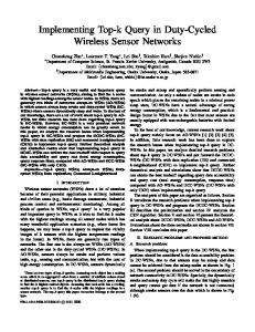
Fig. 2. A schematic view demonstrating the quadratic area increase of a simple SRAM bitcell as the number of ports increases from (a) one to (b) two to (c) four ports.
stacked together, the density of the B2B vias are no worse than the F2B vias. Furthermore, the F2F vias do not pass through the device layer, and therefore do not impose any floorplanning and placement constraints on the underlying devices. III. P LANAR (2D) R EGISTER F ILES Register files are structurally similar to on-chip caches in that both consist of regular arrays of 6T SRAM cells. However, on-chip caches have much larger capacity and require both tag and data arrays. Register files typically have lower capacity requirements and do not have a tag array. However, modern superscalar processors capable of issuing many instructions per cycle require a large number of read and write ports from the register file, and the size of an SRAM cell increases dramatically with increasing port requirements. Figure 2 shows SRAM cells with (a) one port, (b) two ports, and (c) four ports. While Figure 2 illustrates a simplistic SRAM cell design (for example read-port isolation transistors have been omitted for clarity), it is still useful to demonstrate the quadratic increase in area with respect to the port count. The area explosion forces all of the wordlines and bitlines to also increase in length that in turn increases both access latency and power consumption. The physical register file is a critical component of
R31[63:32] R31
Wordline 4 Wordline 3
1−to−16 Decoder
R16
R15
Wordline 4 Wordline 3
b’
R0[63:32] Sense Amps
MSB Out
Wordline 1 Wordline 0
1−to−2 Decoder 1−to−16 Decoder
2−to−1 Muxes Sense Amps
Read−Only Bitlines Wordline 1 Wordline 0
R0 1−to−32 Decoder
R0[31:0]
Data Out
(a)
b
b
b
b
Sense Amps
LSB Out
(b)
Port 0 Bitlines
Port 1 Bitlines
(c)
(d)
Fig. 3. 3D register file organizations achieved through (a) register-partitioning, (b) bit-partitioning, (c) port-splitting, and (d) a port-splitting alternative that only uses one die-to-die via per bitcell. A ◦ represents a die-to-die via.
modern processors in terms of impact on clock frequency and instructions per second (IPC) rates. As a result, many microarchitecture-level proposals have been made to deal with the size, latency and power of the physical register file, including register caching [22] and register file banking [23]. While these techniques can reduce the average latency of register file access, they significantly complicate of the processor data and control paths. Increases in processor clock frequency and the relative decrease of the speed of wires only exacerbate the problem. Another example of the poor scaling of register file latency and area can be found in the Alpha 21264’s 4issue integer execution core which would normally require an 8-read port, 4-write port register file. Instead, the designers chose to duplicate the entire contents of the register file such that each copy only needs half as many read ports [24]. Two full copies of a moderately ported register file proved to be smaller and faster than a single highly-ported structure. Since the register file is dominated by wire, 3D may provide an effective means for controlling the latency, power and area of the large physical register files required by modern highperformance processors. IV. 3D R EGISTER F ILES There are many possible designs for register files in a 3D integration technology. We propose three different strategies for partitioning the register file across multiple die. IV-A. Register-Partitioned (RP) 3D-Register Files A two-die register-partitioned (RP) 3D register file takes half of the register entries and places them on the second die. Figure 3(a) illustrates a 32-entry register file where the bottom die contains registers R0 through R15, and the top die contains R16 through R31. A result of this topology is that the vertical distance (along the bitlines) has been halved, which can greatly reduce the latency and power associated with toggling the bitlines. The row decoder’s height has also been halved, which reduces the length of the critical path associated with accessing the farthest entry in the register file. The overall footprint of
the register file has also been halved, which may enable more compact processor floorplans. To implement a 4-die RP 3D register file, the register entries would simply be partitioned such that one quarter of the entries reside on each die. The row decoder can be further decomposed in a manner similar to the 2-die version. Note that while Figure 3(a) shows a 32-entry register file, with a single read port, the physical register file of modern high-performance processors may have 80 [24] or 128 [25] entries. As the number of in-flight instructions increase, the physical register file size will also grow. The large number of read and write ports also exacerbates the area and wire lengths of the register file. Furthermore, the width of each register has increased over time from 32 bits to 64 bits, and even 128 bits for some instruction set architectures (e.g., Intel’s SSE3 ISA extension provides 128-bit registers). IV-B. Bit-Partitioned (BP) 3D-Register Files The bit-partitioned (BP) 3D register file stacks different bits of the same register across the different die. The BP register file can be viewed as the dual of the RP organization: one folds the register file upon itself in the horizontal direction while the other folds in the vertical direction. Figure 3(b) shows a 2-die 64-bit 32-entry bit-partitioned register file where the bottom die stores the least significant bits of the register values and the top die stores the most significant bits. The bit-partitioned register file reduces the wire length and gate loading on the wordline, which provides both latency and energy benefits. While Figure 3(b) shows the bits of each register partitioned by significance, one could instead store the bits in odd positions on one die and the bits in even positions on the other die. Choosing one over the other does not impact the area, latency or power of the 3D BP register file. However, the choice should be made to match the datapaths throughout the rest of the processor. For example, if one implements a 3D integer ALU partitioned by significance (X[0:31]+Y[0:31] on one die, X[32:63]+Y[32:63] on the second die) [26], then the register file bit-partitioning should also be arranged by significance to avoid unnecessary d2d routing between the register file outputs
and the ALU inputs. The BP 3D register file requires that the row decoder outputs be fanned out to the different die. This extra communication incurs a small overhead, but the latency reduction due to the halving of the wordline length still provides a significant net benefit. For a 4-die organization, the overhead of row decoder output fan out increases, but only slightly because the fan-out trees scale well with increasing die count. IV-C. Port-Split (PS) 3D-Register Files For on-chip caches, the individual SRAM cells are very small to maximize the capacity of the cache, while the areaper-bit for a register file cell is dominated by the wordlines and bitlines for implementing multiple read and write ports. Tsai et al. suggested that the relative size of a 6T SRAM cell and a d2d via make it difficult to take an individual 6T cell and split it across multiple die [14]. However, register file SRAM cells have a substantially larger footprint (due to the high port count) which may provide the opportunity to allocate one or two d2d vias for each cell. Figure 3(c) shows a 2-die portsplit (PS) SRAM cell where each die contains the bitlines, wordlines and access transistors for half of the ports (either read or write). Two d2d vias are requires per bit-cell to route the outputs of the chained inverters to the second die. The PS register file provides substantial benefits in terms of area footprint reduction. Stacking the wordlines on top of each other halves the height, while stacking the bitlines halves the width. A 50% reduction in both dimensions leads to an overall footprint reduction of 75% for the SRAM array. The total register file reduction is slightly less because structures like the row decoder and sense amps may not observe as large of a compaction benefit. This substantial area reduction also translates into latency and energy savings because both bitline and wordline lengths have been halved. Depending on the register file design parameters and the relative size of d2d vias, it may not be possible to allocate two die-to-die vias per bit cell. Figure 3(d) shows an alternative implementation of a 2-die port-split (PS) 3D register file cell where only a single d2d via is used to route the data bit b to the second die. On the upper die, an extra inverter is required to recompute the complement bit b. This shows how in some situations, logic duplication may be used to tradeoff against excessive inter-die communication. A limitation of the single-via configuration is that the ports on the top die can only support read operations because there is no path to access the “true” b storage node.1 This limitation is likely not critical as the number of write ports is typically much less than the number of read ports. With two d2d vias per cell, a third alternative would be to split the back-to-back inverters across the two die. This would place all of the b bitlines on (say) the bottom die, 1 One could conceivably build a single-ended write port that only changes the value of node b and simply relies on the SRAM cell itself to override the b node, but this would increase the write latency and substantially increase the duration of the short-circuit interval where both PMOS pull-up and NMOS pull-down circuits are active.
and all of the b bitlines on the top cell. We do not evaluate this configuration as it has several disadvantages. First, the wordlines must be replicated across both die (similar to the BP register file configuration) which eliminates the wirelength reduction in one dimension. Second, splitting the differential bit-lines across more than one die may require designing sense amplifiers that are themselves partitioned across more than one die. The technique also does not scale to beyond a two-die organization. IV-D. Hybrid Configurations Register files implemented across four (or more) die can use a combination of the partitioning strategies described above. This may be particularly useful in an alternating F2F/B2B die-stacking organization where the available d2d via density changes between pairs of die. In a 4-die stack with alternating F2F interfaces, one could first use register-partitioning to assign half of the registers to dies 0/1 and the other half to dies 2/3, which limits the usage of the coarser B2B vias to the periphery of the main SRAM array. Then among each pair of F2F die, port-partitioning could be employed to exploit the denser F2F interface within the SRAM array. V. C IRCUIT L ATENCY AND E NERGY S IMULATION We use HSpice to obtain the critical path latency and overall energy consumption of SRAM register files. We generate a custom netlist for the different register file configurations based on parameters such as the number of entries, bitwidth per entry, number and type of ports, and 2D vs. 3D organization. Our HSpice simulations use the Berkeley 70nm BSIM transistor models [27] and wire parameters extrapolated to 70nm from a TSMC 180nm technology. We sweep through a range of transistor sizings to minimize the latency of our register file configurations. We use a distributed RC-ladder model for all of the wires in the circuits. For a two-die stack, the distance between the top metal layers on the two die is very small, and the pitch of the D2D vias are of the same order as the top level metal [28]. While the pitch of current manufacturable d2d vias is already only 2.4µm and 4µm for F2F and B2B interfaces [21], respectively, we assume that the d2d sizes will continue to scale at least for a few generations. For our circuits, we used a 1.0µm pitch for the F2F vias, and a 2.0µm pitch for the B2B vias. Furthermore, we assume a Cu-Cu 3D integration technology, which means that the d2d vias are made of the same copper as the traditional on-die interconnects, and therefore have similar unit resistance and capacitance. We assume that the d2d via lengths (die-to-die distance) is 10µm and 20µm for the F2F and B2B interfaces, respectively. We include an additional resistance equal to a top-level via to simulate the contact resistance where the two halves of the d2d via are bonded together. We evaluated physical register file designs for a highperformance superscalar processor. In particular, we consider a four-wide superscalar machine which means the processor core can execute four instructions per cycle. Each of the
TABLE II
TABLE I ACCESS LATENCIES OF PHYSICAL REGISTER
FILES FOR A
4- WIDE
SUPERSCALAR PROCESSOR , AND THE RELATIVE CHANGE IN LATENCY COMPARED TO THE BASELINE
four instructions requires two read ports and one write port. Furthermore, to retire four instructions per cycle, an additional four read ports are needed to read the physical register contents before updating the architected (committed) register file. The total port requirement is 12 read ports and 4 write ports. We assume a register file layout where one half of the bitlines flank either side of the decoders, thus reducing the critical path length of the wordline. In some microarchitectures, the physical register file also contains the instruction status information required for maintaining in-order retirement of instructions; each of our registers contains 160 bits of data [29]. We simulate a 128-entry register file which is representative of modern processors as well as a 256-entry version to model future register file demands. VI. R ESULTS The 3D implementations of the physical register file have the potential to substantially reduce both the latency and power associated with long wires. In the results described below, we compare a baseline 2D/planar implementation of a physical register file to a variety of 3D organizations. In particular, we evaluated both 2-die and 4-die versions employing the different stacking strategies explained earlier in the paper. The overall access latency reduction due to 3D varies depending on the stacking approach. Table I lists the access latencies in picoseconds for each of the register file configurations considered. For the 128-entry, 2-die, 3D register file, the BP approach provides the greatest latency reduction. The wordline is heavily loaded by the two access transistors per column, and so splitting the wordline across two die reduces a major component of the wire latency. When considering a 256-entry register file, the height of the overall structure increases, thus making the row decoder and bitline/senseamp delay more critical. In this situation, the RP approach provides greater benefit. Although the PS organization has a substantially smaller footprint, it does not provide the fastest
4- WIDE
SUPERSCALAR PROCESSOR , AND THE RELATIVE CHANGE IN LATENCY
2- DIE AND 4- DIE CONFIGURATIONS ARE BOLDED .
RF Size 128
ACCESS OF PHYSICAL REGISTER FILES FOR A
RF Size 128
Base 2D 4.46 nJ
256
11.24 nJ
RF Size 128 256
RP/RP 2.84 nJ -36.3% 3.69 nJ -67.2%
2D/ PLANAR
RP 3.50 nJ -21.5% 4.67 nJ -58.5%
BP/BP 4.35 nJ -2.47% 9.71 nJ -13.6%
IMPLEMENTATION .
3D/2-die BP 4.55 nJ +2.02% 10.43 nJ -7.21%
3D/4-die PS/PS 3.78 nJ -15.2% 8.49 nJ -24.5%
PS 3.82 nJ -14.4% 9.03 nJ -19.7%
BP/RP 3.38 nJ -24.2% 4.70 nJ -58.2%
BP/PS 3.82 nJ -14.3% 8.24 nJ -26.7%
performance due to fact that the access transistor loading on the wordlines has not been reduced. There are more design options when implementing structures across four stacked die. Table I also lists the latency benefits for implementing the register file in a 4-die stack. The notation X/Y indicates that the register file is split across the F2F boundary using partitioning scheme X, and split across the B2B boundary using partitioning scheme Y. For example, the BP/RP organization places one half of the registers on dies 0/1 and the other half on dies 2/3 (RP across the B2B interface), and then within each pair of die each register’s bits are split half on one die and half on the other. The best performing register file organizations make use of hybrid partitioning strategies. This makes sense as the application of one partitioning technique may reduce the latency of a critical wire delay by a significant amount such that it is no longer the worst delay in the circuit. A second different partitioning can then address the new worst delay. Our results show that a 128-entry register file can be sped up by 28.6% and a 256entry register file observes a 36.0% improvement. This latency reduction may potentially be converted into a clock frequency increase or a reduction in the number of cycles necessary to access the register file. The performance improvements of the hybrid configurations highlight the generality of the 3D stacking techniques. For different processor configurations, the critical wire delay components within the register file will likely be different. The benefits of 3D are not limited to specific processor microarchitectural parameters; that is, for each situation, a circuit designer can choose the appropriate 3D stacking strategy to provide a latency reduction. In addition to reducing the access latency of the physical register file, the 3D organization can also reduce the power consumption of the overall structure. Table II lists the energy required for one read operation from the physical register file. The 3D configuration that minimizes energy consumption is not necessarily the configuration that has the lowest
latency. For example, the wordline switching delay in the 128-entry scheduler is critical for performance, but from a energy consumption perspective, the many parallel output bits require far more energy. Our physical register file width of 160 bits would require toggling 320 bit lines and switching 160 sense amplifiers. The RP approach effectively halves the bitline length for each doubling of the number of stacked die. The shorter bitlines greatly reduces the loading on the sense amp, which in turn may be sized smaller to consume even less energy. For all 3D configurations evaluated, the RP always provides the greatest energy reduction. For the 2-die BP configuration, the energy consumption actually increases slightly compared to the baseline configuration. This is simply due to the fact that the BP organization does not change the bitline length or loading, and we had resized some of the transistors in the sense amps to further improve the latency at the cost of a slight increase in power. VII. S UMMARY 3D integration presents an opportunity to greatly reduce the impact of the poor scaling of wire delay. We have studied one particular microarchitectural module and demonstrated how a 3D circuit implementation can simultaneously provide both performance and power benefits by reducing the lengths of critical wires. There are many opportunities for further research in the application of 3D integration to the design of high performance microprocessors, and also to other areas such as embedded processors, DSPs, and other computing devices. Much more work is required at many levels, including circuit design, microarchitectures, and CAD tool support. ACKNOWLEDGMENTS Funding and equipment for this project have been provided by Intel Corporation and a grant from the Microelectronics Advanced Research Corporation (MARCO). R EFERENCES [1] G. E. Moore, “Cramming More Components Onto Integrated Circuits,” Electronics, April 1965. [2] Semiconductor Industry Association, “The National Technology Roadmap for Semiconductors,” 1999. [3] V. Agarwal, M. S. Hrishikesh, S. W. Keckler, and D. Burger, “Clock Rate Versus IPC: The End of the Road for Conventional Microarchitectures,” in Proceedings of the 27th International Symposium on Computer Architecture, Vancouver, Canada, June 2000, pp. 248–259. [4] R. Ho, K. W. Mai, and M. A. Horowitz, “The Future of Wires,” Proceedings of the IEEE, vol. 89, no. 4, pp. 490–504, April 2001. [5] S. Borkar, “Design Challenges of Technology Scaling,” IEEE Micro Magazine, vol. 19, no. 4, pp. 23–29, July 1999. [6] R. Ronen, A. Mendelson, K. Lai, S.-L. Lu, F. Pollack, and J. P. Shen, “Coming Challenges in Microarchitecture and Architecture,” Proceedings of the IEEE, vol. 89, no. 3, pp. 325–340, March 2001. [7] R. Gonzalez and M. Horowitz, “Energy Dissipation in General Purpose Microprocessors,” IEEE Journal of Solid-State Circuits, vol. 31, no. 9, pp. 1277–1284, September 1996. [8] M. J. Flynn, P. Hung, and K. W. Rudd, “Deep-Submicron Microprocessor Design Issues,” IEEE Micro Magazine, vol. 19, no. 4, pp. 11–22, July 1999. [9] D. Brooks, P. W. Cook, P. Bose, S. E. Schuster, H. Jacobson, P. N. Kudva, A. Buyuktosunoglu, J.-D. Wellman, V. Zyuban, and M. Gupta, “Power-Aware Microarchitecture: Design and Modeling Challenges for Next-Generation Microprocessors,” IEEE Micro Magazine, vol. 20, no. 6, pp. 26–44, November 2000.
[10] V. Srinivasan, D. Brooks, M. Gschwind, P. Bose, V. Zyuban, P. N. Strenski, and P. G. Emma, “Optimizing Pipelines for Power and Performance,” in Proceedings of the 35th International Symposium on Microarchitecture, Istanbul, Turkey, November 2002, pp. 333–344. [11] S. Palacharla, “Complexity-Effective Superscalar Processors,” Ph.D. dissertation, University of Wisconsin, 1998. [12] D. Nelson, C. Webb, D. McCauley, K. Raol, J. R. II, J. DeVale, and B. Black, “A 3D Interconnect Methodology Applied to iA32-class Architectures for Performance Improvements through RC Mitigation,” in Proceedings of the 21st International VLSI Multilevel Interconnection Conference, Waikoloa Beach, HI, USA, September 2004. [13] K. Puttaswamy and G. H. Loh, “Implementing Caches in a 3D Technology for High Performance Processors,” in Proceedings of the International Conference on Computer Design, San Jose, CA, USA, October 2005. [14] Y.-F. Tsai, Y. Xie, N. Vijaykrishnan, and M. J. Irwin, “ThreeDimensional Cache Design Using 3DCacti,” in Proceedings of the International Conference on Computer Design, San Jose, CA, USA, October 2005. [15] P. Reed, G. Yeung, and B. Black, “Design Aspects of a Microprocessor Data Cache using 3D Die Interconnect Technology,” in Proceedings of the International Conference on Integrated Circuit Design and Technology, Austin, TX, USA, May 2005, pp. 15–18. [16] Tezzaron Semiconductor, “WWW Site,” http://www.tezzaron.com. [17] Samsung Electronics Corporation, “Samsung Electronics Develops World’s First Eight-die Multi Chip Package for Multimedia Cell Phones,” January 10 2005, press Release from http://www.samsung.com. [18] P. Morrow, M. J. Kobrinsky, S. Ramanathan, C.-M. Park, M. Harmes, V. Ramachandrarao, H. mog Park, G. Kloster, S. List, and S. Kim, “Wafer-Level 3D Interconnects Via Cu Bonding,” in Proceedings of the 21st Advanced Metallization Conference, San Diego, CA, USA, October 2004. [19] R. Reif, A. Fan, K.-N. Chen, and S. Das, “Fabrication Technologies for Three-Dimensional Integrated Circuits,” in Proceedings of the 3rd International Symposium on Quality Electronic Design, San Jose, CA, USA, March 2002, pp. 33–37. [20] S. Das, A. Fan, K.-N. Chen, and C. S. Tan, “Technology, Performance, and Computer-Aided Design of Three-Dimensional Integrated Circuits,” in Proceedings of the International Symposium on Physical Design, Phoenix, AZ, USA, April 2004, pp. 108–115. [21] S. Gupta, M. Hilbert, S. Hong, and R. Patti, “Techniques for Producing 3D ICs with High-Density Interconnect,” in Proceedings of the 21st International VLSI Multilevel Interconnection Conference, Waikoloa Beach, HI, USA, September 2004. [22] R. Balasubramonian, S. Dwarkadas, and D. Albonesi, “Reducing the Complexity of the Register File in Dynamic Superscalar Processors,” in Proceedings of the 34th International Symposium on Microarchitecture, Austin, TX, USA, December 2001, pp. 237–248. [23] J. H. Tseng and K. Asanovi´c, “Banked Multiported Register Files for High-Frequency Superscalar Microprocessors,” in Proceedings of the 30th International Symposium on Computer Architecture, San Diego, CA, USA, May 2003, pp. 62–71. [24] R. E. Kessler, “The Alpha 21264 Microprocessor,” IEEE Micro Magazine, vol. 19, no. 2, pp. 24–36, March–April 1999. [25] G. Hinton, D. Sager, M. Upton, D. Boggs, D. Carmean, A. Kyler, and P. Roussel, “The Microarchitecture of the Pentium 4 Processor,” Intel Technology Journal, Q1 2001. [26] J. Mayega, O. Erdogan, P. M. Belemjian, K. Zhou, J. F. McDonald, and R. P. Kraft, “3D Direct Vertical Interconnect Microprocessors Test Vehicle,” in Proceedings of the ACM Great Lakes Symposium on VLSI, Washington, DC, USA, April 2003, pp. 141–146. [27] Y. Cao, T. Sato, D. Sylvester, M. Orshansky, and C. Hu, “New Paradigm of Predictive MOSFET and Interconnect Modeling for Early Circuit Design,” in Proceedings of the 2000 Custom Integrated Circuits Conference, Orlando, FL, USA, May 2000, pp. 201–204. [28] Y. Deng and W. Maly, “2.5D System Integration: A Design Driven System Implementation Schema,” in Proceedings of the Asia South Pacific Design Automation Conference, Yokohama, Japan, January 2004, pp. 450–455. [29] J. P. Shen and M. H. Lipasti, Modern Processor Design: Fundamentals of Superscalar Processors. McGraw Hill, 2005.
Implementing Register Files for High-Performance ... - CiteSeerX
Abstractâ 3D integration is a new technology that will greatly increase transistor density ... improvement with a simultaneous energy reduction of 58.5%, while a four-die version ..... Figure 3(d) shows an alternative implementation of a 2-die ...
MIT Laboratory for Computer Science, 200 Technology Square, Cambridge, MA 02139. {jhtseng ... a banked register file with much simpler and faster control .... tion window in the next wakeup phase to allow back-to- ..... conflicts in a system with eig
together with a much simpler and faster control logic suitable for a deeply pipelined high-frequency superscalar processor [4]. Our control scheme does not place any register bank arbitration in the critical wakeup-select loop but instead speculative
School of Electronic and Electrical Engineering, University of Birmingham, Edgbaston, ... describe a system which uses an FPGA for the decoding and a PC for pre- and ... Current systems work best if they are allowed to adapt to a new speaker, the ...
Department of Computer Science. University of Massachusetts-Lowell. One University Avenue. Lowell, MA 01854. Abstract. The use of a massively parallel ...
formed by connecting line segments at their endpoints according to a set of geometric ... supercomputer version of the color icon and briefly outline the benefits and ..... The memory limitations of the Terasys forces the use of memory to be an impor
s with unlimited energy supply which serves as a gateway between the sensor network and users ..... the center of the network region. The transmission radius of.
that are awake and black nodes represent the nodes that are asleep, node S ..... [8] V. Raghunathan, C. Schurgers, S. Park, M. Srivastava, and B. Shaw,.
(I)AP Computer Science A; ... (M)Discrete Mathematics for Computer Science; ... (A)a coherent sequence of courses for four or more credits in career and ... (vii)Chapter 130, Subchapter K, of this title (relating to Information Technology); or.
During the upcoming school year, Technology and Innovation in Education (TIE), ... teacher-developed resources now featured on the Smarter Balanced Digital ...
counterexamples to RA-McBride. For example, that Marilyn (credibly) confesses that she murdered someone is a reason to put her on trial for murder (we may ...
the Office of the Econometric Society (contact information may be found at the website ... achievements in mathematics and science go to the best engineering univer- sities. Stability is regarded as a .... tion rules over the domain of pairs of respo
During the upcoming school year, Technology and Innovation in Education (TIE), in partnership with the South Dakota Department of Education (SD DOE), will ...
achievements in mathematics and science go to the best engineering univer- ...... Two-Sided Matching Based Decision Support System for Military Personnel ...
For example, schools in Boston give higher priority to students who live nearby or .... Kesten (2006) showed that the deferred acceptance rule and the top trading cycle rule for ..... light on the mechanics of the deferred acceptance algorithm.
Part II:General Science. Part III:Simple ... Part I:Questions based on Degree in Library & Information Science ... Part X:Information Technology and Cyber Laws.
Identify the figure of speech in the line from Gray's Elegy:The ploughman .... A play that deals with the narcissism of the self-involved hero,who ... D.Good climate ... Who opined that the business of the poet is not to find new emotions,but to use