JOURNAL OF TELECOMMUNICATIONS VOLUME 4, ISSUE 1, AUGUST 2010 25
Implementation of DSSS Technology in Multipath Environment Using SDR Nirmalendu Bikas Sinha, K.Chowdhury and M.Mitra Abstract— In an effort to develop a complete DSSS system for ITS application in our day-to-day life, the authors have experienced a lot of experimentation and modelling which has been put to use for exploting the best possible design. Nowadays, one of the major threats in the field of wireless communication is jamming. Many anti-jamming techniques have been developed in the recent past. Presently known anti-jamming techniques require the communicating devices to have a pre-shared secret that can be used as a secret spreading key between two communicating devices. For DSSS based anti-jamming scheme, the secret key is used to derive the code sequences. The transmitted signal, in this case propagates though the channel undetected by anyone who may be listening. Traditionally, wireless security is considered in link layer design and media access control (MAC) management, including data encryption algorithms and key management in cooperative communication systems. DSSS systems is found to deal with wireless security issues very efficiently at the MAC layer.The performance of the system is critically analysed in presence of narrowband and wideband interference signals in this paper and a highly efficint interference rejection technique is developed for multipath environment using RAKE receiver. It has finally been implemented using SDR in the newly developed DSSS based communication system . Index Terms, — DSSS, RAKE, ITS, MAC, 4G.
—————————— � ——————————
1. INTRODUCTION Recently, mobile communication has begun to permeate every aspect of our daily lives. However, with the development of mobile communications, the frequency spectrum becomes more and more crowded. As a result, the quest for high data rates with a high spectral efficiency is considered for future broadband wireless communication. DSSS is found to provide high spectral efficiency and robustness.For DSSS based anti-jamming
————————————————
• 1Prof. Nirmalendu Bikas Sinha, corresponding author is with the Department of ECE and EIE , College of Engineering & Management, Kolaghat, K.T.P.P Township, Purba- Medinipur, 721171, W.B., India. • 2Kaustav Chowdhury is with the Department of ECE, College of Engineering & Management, Kolaghat, K.T.P.P Township, PurbaMedinipur, 721171, W.B., India. • 3Dr. M.Mitra is with the Bengal Engineering and Science University, Shibpur,W.B,India.
scheme, the secret key is used to derive the code sequences. DSSS systems spread the baseband data signal over a broad bandwidth to achieve anti-jamming protection[1], low-probability of detection and interception(LPI),availability of licence-free ISM (Industrial, Scientific and Medical) frequency-bands ,increase the difficulty of spectrum surveillance , can address multiple users simultaneously and at the same frequency, most powerful air interface for the reverse link of next generation broadband mobile communication system, such as 4G wireless networks and remote sensing, and network throughput[2]-[5]. Traditionally, wireless security is considered in link layer design and media access control (MAC) management, including data encryption algorithms and key management in cooperative communication systems.It has been shown that multi-carrier spread spectrum (MC-
© 2010 JOT http://sites.google.com/site/journaloftelecommunications/
JOURNAL OF TELECOMMUNICATIONS VOLUME 4, ISSUE 1, AUGUST 2010 26
SS) offers high spectral efficiency, robustness and flexibility[6][7] and hence is the best suitable method. Protection against jamming waveforms is provided by purposefully making the information-beating signal occupy a bandwidth far in excess of the minimum bandwidth necessary to transmit it. This has the effect of making the transmitted signal assume a noise-like appearance so as to blend it into the background. The transmitted signal thus enables itself to propagate though the channel undetected by anyone who may be listening. Spread spectrum technique is a method of “camouflaging” the information signal. Implementations in the field of wireless multimedia in the recent years has presented new challenges in the design of DSSS systems having higher interference susceptibility tolerance levels, high data rate transmission, a fast changing physical
channel, wide area coverage, portability, security of transaction(encryption),seamless connectivity and services with different quality of service. Furthermore, strong constraints are introduced into the system design by the fact that some resources such as spectrum and battery power are not in abundant supply. Efficient use of spectrum and new age signal processing techniques forms the basis of developing the new system architecture. The future wireless communication landscape will undoubtedly continue to expand dramatically due to the emergence of new systems driven by the rapid growth in information and multimedia applications that satisfy ubiquitous requirements.
2. FUNCTIONAL ARCHITECTURE OF DSSS SYSTEM
TX
Rx
Spreading
Despreading
l dt
S / P
M-PSK Modulator
Q pnt
TX fRF
PN Code
C H A N N E L
Output Data
M-PSK Demodulator fRF PN Code
RF
Band pass
Baseband
Baseband
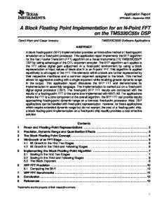
Fig.1. Block diagram of DSSS system architecture. spectrum radio waveform in communication is to allow Spread spectrum (SS) is a means of transmission
simultaneous use of the same frequency spectrum. This is
technique, in which a pseudo noise code, which is
achieved by coding each signal differently from the
independent of data, is employed as a modulation
others. This technique uses PN sequence to spread the
waveform to spread the signal energy over a bandwidth
signal over a wide band, making the signal look like a
much greater than the signal information bandwidth. At
noise. A pseudo noise sequence pnt which is generated at
the receiver, the signal is restored back to its original
the modulator, is used in conjunction with an M array
bandwidth (“despread”) using a synchronized replica of
PSK modulation to shift the phase of the signal pseudo
the pseudo noise code. The purpose of such spread
randomly, at the chipping rate Rc, a rate that is an integer multiple of the symbol rate( Rs)
.
The transmitted
bandwidth is determined by the chip rate and the base-
© 2010 JOT http://sites.google.com/site/journaloftelecommunications/
JOURNAL OURNAL OF TELECOMMUNICATIONS VOLUME 4, ISSUE 1, AUGUST 2010 27
band filtering. The implementation limits the maximum
The reason behind interference rejection capability of a
chip-rate and hence the maximum m spreading. The PSK
spread spectrum signal is that the useful us signal gets
modulation requires a coherent demodulation. A short
multiplied twice by the PN sequence while the
code system uses a PN code length that is much longer
interference signal gets multiplied only once. The Fig.5
than a data symbol. A long code system uses a PN code
represents the frequency spectrums for narrowband
length that is longer than a data symbol, so that a
interference.
different chip pattern is associated with each symbol. Wideband Interference Tc
Multiplication of the received signal with the PN P sequence at the receiver end follows selective dede fRF Rc
fRF Wss
spreading of the data signal which is characterised by
fRF Rc
f
smaller bandwidth and higher power density. The interference signal is uncorrelated with the PN sequence
Fig.2 Frequency spectrum of a DSSS signal for an
and is spread. The spectral signal has a lower low power
instantaneously broadband coherent oherent system
density as compared to the directly transmitted signal. The Fig.6 shown above represents the frequency spectrums for wideband interference. EXPANDED VIEW OF SPREAD SPECTRUM BASED MULTIPATH PROPAGATION SIMULATIONS
Data signal Pseudo sequence
Modulated signal Demodulated signal
Multi path signal
Output of multipath signal
Fig.3 Direct Sequence Spread Spectrum Waveform 08-08-2007
3.
PERFORMANCE
IN
PRESENCE
RF Carrier signal
Fig.4 DSSS based multipath propagation waveforms
INTERFERENCE Narrowband Interference The
narrowband
13
OF
noise
is
spread
multiplication with the PN sequence
over
by
its
. The power
density of the noisy data signal is less as compared to dede spread data signal because only
of noise power is
left in the information baseband signal. Spreading and dede spreading of the signal enables a bandwidth trade for processing gain against narrow band interfering signals.
© 2010 JOT http://sites.google.com/site/journaloftelecommunications/
JOURNAL OF TELECOMMUNICATIONS VOLUME 4, ISSUE 1, AUGUST 2010 28
|dt(f)|
|rxb(f)| DS-signal (spread)
Data signal
|dr(f)|
Narrowband interfrence whitened interference
-Rs
-Rc
f
+Rs
+Rc
f
DS-signal (despread)
-Rc -Rs
+Rs +Rc
f
Fig.5 represents the frequency spectrums for narrowband interference.
-Rs
|dr(f)|
|rxb(f)|
|dt(f)|
Data signal user A
+Rs
wideband interference user B
f
-Rc
DS-signal user A (spread)
+Rc
DS-signal user A (despread)
whitened interference user B
f
-Rc
-Rs
+Rs
+Rc f
Fig.6 represents the frequency spectrums for wideband interference.
4. IMPLEMENTATION OF A DSSS SYSTEM USING
System Generator and sample times for ADC and DAC
A
are set at 1/3e7 sec while DSP bus speed is set to 48 KHz.
RAKE
RECEIVER
IN
A
MULTI-PATH
ENVIRONMENT.
In this model, DSP bus takes care of the modulated signal out of the DSP processor into the FPGA and
To realize the DSSS system FPGA and DSP models were
afterwards it sends the signal to the DAC port for
developed.
transmission. Note: In the SDR, the DAC and ADC ports are directly
A. FPGA model:
connected to the FPGA section. This signal from the DAC is looped back to the Signal
The system generator and board configurations are
WAVE through the ADC port, and then it is resent to the
attached with the model.
DSP processor for the demodulation using the custom
The FPGA clock speed is selected to be 30 MHz
registers.
.Therefore, the simulation time of 33.3 ns is set in the
© 2010 JOT http://sites.google.com/site/journaloftelecommunications/
JOURNAL OF TELECOMMUNICATIONS VOLUME 4, ISSUE 1, AUGUST 2010 29
Fig.7. The FPGA system model for DSSS systems
Fig.8. DSP model for DSSS system using RAKE receiver
B. DSP model: Transmitter Section: In the DSP part a multi-path channel is realized by delaying the original signal and then combining the two signals to achieve a multi-path signal. Rest of the transmitter is same as the DSSS system of the above experiment. Receiver Section: The received incoming signal from custom register is divided into two segments which form two fingers of the
Fig. 9.(a) Line of Sight Signal from 1st Finger (b) Despreading code (c) Multi-path Signal from 2nd Finger
RAKE receiver. In each finger one multi-path signal enters and is being
CONCLUSION
individually de-spread. It is then passed through the integrate and dump circuit which accumulate the 13 bit data and then generate the resulting symbol.
The burning desire or demand for wireless security in the communication sector has been quenched since the inception of DSSS systems. The development of DSSS architecture
has
been
efficiently
designed
and
subsequently implemented successfully through the development of its hardware and software models. The problems of multipath effect can be successfully mitigated by the help of RAKE receivers. Finally, the author has focused on hardware implementation of the
© 2010 JOT http://sites.google.com/site/journaloftelecommunications/
JOURNAL OF TELECOMMUNICATIONS VOLUME 4, ISSUE 1, AUGUST 2010 30
newly developed DSSS communication model which is
towards
then implemented through SDR.
Telecommunication Engineering at BESU. Since 2003, he
the
Ph.D
degree
in
Electronics
and
has been associated with the College of Engineering and REFERENCES
Management, Kolaghat. W.B, India where he is currently an Asst.Professor is with the department of Electronics &
[1] G. J. Foschini and M. J. Gans,“On limits of wireless
Communication
communications in a fading environment when using
Instrumentation
multiple antennas”, Wireless. Personal Commun., vol. 6,
Interests are in the area of signal processing for high-
pp. 311–335, Mar. 1998.
speed digital communications, signal detection, MIMO,
Engineering Engineering.
& His
Electronics current
&
research
[2] L. Li and L. B. Milstein, “Rejection of pulsed CW
multiuser communications,Microwave /Millimeter wave
interference in PN spread spectrum signals using
based
complex adaptive filters,” IEEE Trans. Commun., vol.
,semiconductor Devices, Remote Sensing, Digital Radar,
COM-31, pp. 10–20, Jan. 1983.
RCS Imaging, and Wireless 4G communication. He has
[3] L. B. Milstein, “Interference rejection techniques in
published
spread spectrum communications,” in Proc. IEEE, vol. 76,
international Conference, proceedings and journals.He is
pp. 657–971, June 1988.
presently the Chief Editor, Editor and reviewers in
[4] Shiro Kondo, Laurence B. Milstein, ““Performance of
different international journals.
Broadband
large
Wireless Mobile
number
of
Communication
papers
in
different
Multicarrier DS CDMA Systems”, IEEE Transactions on Communications, vol. 44, No. 2, Feb 1996.
Kaustav
Chowdhury
[5] M.Rahman, and P.Ernstrom, “Repeaters for Hotspot
Department
of
is
pursuing
Electronics
&
B.Tech
in
the
Communication
Capacity in DSCDMA Networks,” IEEE Trans. Veh.
Engineering at College of Engineering and
Technol., Vol.53, No.3, pp. 626-633, May 2004.
Management, Kolaghat, under WBUT in
[6]
N.B.sinha,
D.Kandar,
S.K.Sarkar,
2011, W.B, India. His areas of interest are
“Experimental studies and simulations based prediction
in Microwave /Millimeter wave based
of a better MIMO-OFDM combined system for broad
Broadband
band mobile and wireless communication”, International
Communication and digital electronics.
Journal Progress
R.Bera
and
Wireless
Mobile
in Electromagnetics Research C (PIER
C), Vol. 2, pp. 47–64, 2008.
Dr. Monojit Mitra is an Assistant Professor in the
[7] Bera.R, Bera.J, Sil. S, Sinha. N.B, Dogra.S, “Dedicated
Department of ETC of BESU, Shibpur. He obtained his
short range communications (DSRC) for intelligent
B.Tech, M.Tech & Ph. D .degrees from
transport system, proceedings of IEEE on Wireless and
Calcutta University. His research areas are in
Optical Communication Networks (WOCN '06), Digital
the field of Microwave & Microelectronics,
Object Identifier 10.1109/WOCN.2006.1666607, PP. , 11-
especially
13 April 2006.
frequency solid state devices like IMPATT.
in
the
fabrication
of
high
He has published large number of papers in different national and international journals. He has handled Prof. Nirmalendu
Bikas
Sinha
received the B.Sc
(Honours in Physics), B. Tech, M. Tech degrees
in
Radio-Physics
sponsored research projects of DOE and DRDO. He is a member of IETE (I) and Institution of Engineers (I).
and
Electronics from Calcutta University, Calcutta,India,in1996,1999
and
2001,
respectively. He is currently working
© 2010 JOT http://sites.google.com/site/journaloftelecommunications/