1
Hitchhike: A Preamble-based Control Plane for SNR-sensitive Wireless Networks Xiaoyu Ji, Member, IEEE, Jiliang Wang, Member, IEEE, Mingyan Liu, Fellow, IEEE, Yubo Yan, Member, IEEE, Panlong Yang, Member, IEEE and Yunhao Liu, Fellow, IEEE Abstract—Recently, carrying control signals on passing data packets has emerged as a promising direction for efficient control information transmission. With control messages carried on data payload, the extra air time needed for control packets like RTS/CTS is eliminated and thus channel utilization is improved. However, carrying control signals on the data payload of a packet requires the data packet to have a sufficiently large SNR, otherwise both the data packet and the control messages are lost. In this paper, we propose Hitchhike, a technique that utilizes the preamble field to carry control messages. Hitchhike completely decouples the control messages from the payload and therefore the superposition of (multiple) control messages has little adverse effect on the operation of the payload decoding. We implement and evaluate Hitchhike in the USRP2 platform with 5 nodes. Evaluation results demonstrate the feasibility and effectiveness of Hitchhike. Compared with the state-of-the-art, e.g., Side-channel in 802.15.4, Hitchhike improves the detection accuracy of control messages by 40% and reduces the data loss caused by control messages by 15%. Index Terms—Control plane, Preamble, Wireless Networks, SNR, Throughput
I. I NTRODUCTION UE to the scarcity of wireless spectrum, it is a common practice within wireless protocols to send control messages as data messages, see e.g., ZigBee and Wi-Fi. As a prime example, the control messages RTS/CTS used in CSMA/CAtype of protocols are strictly speaking data packets containing control information. While this is certainly a very convenient way of disseminating and exchanging control information, the overhead is significant: these extra data packets occupy a disproportionately large portion of air time compared to the amount of information they carry [1]. Recently, there has emerged a promising new direction for efficient control message delivery, one that tries to build the control plane on top of real data packets, see e.g., [2], [3]. The basic idea is to embed control information in data messages so the two may be transmitted concurrently. This is illustrated in an example shown in Fig. 1(a). Bob wants to transmit a control message to Carol telling her that he is Bob (the equivalent of the “HELLO” control packet in many protocols). Instead of using a separate data packet for this, Bob tries to ride his message on top of a data packet from Alice to Carol as follows. He intentionally interferes a few bits of Alice’s packet and uses these bits to convey his control information. Carol receives the (slightly) corrupted data packet and extracts the control information from Bob by calculating the relative distance among those bits. The original data message can also be recovered due to the modulation redundancy [2], [4] in physical layer (PHY) implementation. This so-called in-band
D
Bob
Bob is here
ĀI am Bobā Preamble 10101101
Alice
Preamble 10101101
(In channel)
Carol
10101101 The data
(a) Payload based mechanism (Side-channel).
Bob
ĀI am Bobā
Bob is here 10101101
Alice
Preamble 10101101
(In channel)
Carol
10101101 The data
(b) Hitchhike, a preamble based approach. Fig. 1. Illustration of Hitchhike compared with payload based mechanism. In Side-channel (Fig. 1(a)), the control message from Bob is carried on the payload of the packet form Alice to Carol. While in Hitchhike (Fig. 1(b)), the control message is carried on the preamble of the packet.
control message1 transmission mechanism eliminates the extra transmission time for control messages and therefore improves channel utilization. However, there are three problems with the above mechanism. First of all, this mechanism requires high SNR for the data packet. The basic assumption for this mechanism to work is that the payload has a large redundancy, while in reality, due to the existence of noise and interference, the redundancy margin may be very limited [5]–[7]. As a result, it is possible to corrupt the data bits in the payload beyond recovery by inserting the control message, especially under low SNR conditions. Second, even if the control message does not adversely affect the decoding of the payload, it may be difficult to correctly decode the control message under low SNR conditions. There may be other “error bits” caused by noise and unintentional interference, which could mislead the receiver to incorrectly decode and interpret the control message. Lastly, this mechanism suffers when multiple users try to transmit control messages via the same data payload. In Fig.1(a), if another user, say David, also transmits his control message on top of Alice’s packet, then the two control messages interleave and Carol may not be able to decode either of them. In this paper, we propose Hitchhike, a novel technique that carries control messages on the preamble rather than data payload, and decodes them using correlation. As shown in Fig. 1(b), the control message from Bob is sent as a unique signal pattern superposed on the preamble field of the packet form Alice to Carol. Carol then detects both the preamble of 1 We
use control for short in the rest of this paper.
2
the packet and the control signal from Bob by correlation. Compared with payload-based mechanism, preamble-based control plane has the following advantages. First, by carrying the control in the preamble field, the data payload is decoupled from control signaling. As a result, the decoding of control does not interfere with the decoding of data bits. Indeed, detecting a preamble requires far lower SNR than decoding a bit does, thus using this technique control messages can be transmitted at extremely low SNR levels, without affecting their detection accuracy. This also means that, there is no increased SNR requirement on the payload as it is not threatened by interference from the control message. Last but not least, multiple control messages can be transmitted concurrently over a common data packet’s preamble field and detected using a bank of correlators. This technique, however, is not without its own challenges. First of all, the superposition of control signals over a preamble may cause missed detection of the preamble which leads the whole packet to be missed. To address this, we need to carefully design orthogonal codes for control messages that have appropriate lengths with respect to the signal pattern of the preamble. The second challenge lies in the detection and recovery of control information from the mixed controlpreamble signal. To eliminate the impact of the preamble in the detection of control, we design a subtraction-detection algorithm in which the preamble signal is subtracted from the mixed signal to provide higher detection accuracy for control signals. Finally, we need to ensure that the control signals can ride exactly on the preambles, i.e., sufficiently synchronized with the preamble. For this we propose to utilize the beginning part of a preamble a synchronization mechanism signaling the incoming of a preamble. We design and implement Hitchhike on the GNURadio/USRP2 platform, and our experiments involve 5 such nodes. Our evaluation results indicate that placing the specially designed control signals on a preamble has little adverse effect on the normal operation of the preamble. Moreover, the control signals carried by the preamble can also be detected accurately. Compared with the state-of-the-art technique, Sidechannel [2], the detection accuracy of Hitchhike is 40% higher and the side effect upon data decoding is 15% lower in average. Our main contributions are summarized as follows: •
•
•
We propose a novel concept that utilizes preambles for carrying control information. We contrast this with the payload-based mechanisms and highlight its advantages in being able to operate under lower SNR requirements and in supporting multiple users. We design and implement Hitchhike, a mechanism that uses the above concept to deliver control messages in 802.15.4 networks. We design orthogonal codes for control messages and develop the subtraction-detection algorithm for their detection. We validate the feasibility of Hitchhike and evaluate its performance with 5 nodes on the GNURadio/USRP2 platform. The results indicate that the preamble and the designed control messages can work in harmony in Hitchhike.
32 '0's PHY layer
Preamble
MAC sublayer frame SFD
Len
Payload
Fig. 2. Format of a packet in the 802.15.4 PHY layer. The preamble field has a repeated signal pattern.
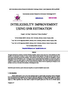
The rest of this paper is organized as follows. Section II details the motivation of this work. In Section III we introduce the design detail of Hitchhike. In Section IV, we present the implementation of Hitchhike, followed by a performance evaluation in Section V. We discuss the potential applications of Hitchhike in Section VII and the related work in Section VIII. We conclude the paper in Section IX. II. M OTIVATION In this section we detail the motivation behind the concept and design of Hitchhike. We start with a primer on the use of preamble and related physical layer details. We then investigate the chances in preambles by looking at its special structure and mechanism compared with payload decoding. In the end we present the main challenges in using preambles to carry control messages. A. A Primer on Preamble In wireless networks with IEEE 802.15.4 [8] and 802.11 [9] PHY layer, a data packet is mainly composed of four parts: the preamble field, SFD (Start of Frame Delimiter), length and the payload field. As shown in Fig. 2, the preamble is the beginning of the packet followed by SFD and Len, and the rest is the payload. Preamble is primarily used for a receiver to detect the incoming/arrival of a packet and perform synchronization needed for packet reception [10]. The SFD field indicates the start of the MAC sublayer frame and Len specifies the length of the payload. A preamble has a known repeated pattern so that the receiver can use auto-correlation with the received signal to determine its presence in the air. To ensure detection robustness, a preamble is designed to have a repeated pattern. For example, under the 802.15.4 specification, a preamble contains 32 binary ‘0’s which is in fact 8 repeated ‘0’ symbols [8]. The correlation operation would output a spike if a preamble is present in the signal. At the same time, the receiver synchronizes itself with the sender and calculates parameters like carrier frequency offset (CFO). It begins receiving the payload signal after the SFD and length checking. B. Opportunity to Leverage Preamble Margin As mentioned above, a preamble is specially designed in order to accurately detect the start of a packet for the receiver. To this end, the PHY mechanism requires that the preamble part should have high redundancy. For example, in the IEEE 802.15.4 specification [8], the preamble doesn’t only have a repeated pattern, but also have a sufficient length, i.e, 8 ‘0’ symbols, even though it can be achieved with only 2 (according to the CC2420 chip manual [11]). With this redundancy, a receiver is able to find the arrival of a packet even in poor SNR environments. By looking at the high redundancy, we
Success Ratio (%)
3
100 90 80 70 60 50 40 30 20 10 0
Preamble detection
Payload decoding SNR Gap
test 1 test 2 test 3 test 4 test 5 -10
-5
0
5
10
15
SNR (dB)
Fig. 3. The SNR gap between decoding the payload and detecting the preamble. The gap can be as large as almost 10 dB.
question whether we could make use of this opportunity and put the control messages on top of the preamble instead of the payload, in which case the payload is not vulnerable. To verify this, we conduct an experiment with two USRP2 devices running with 802.15.4 PHY and placed 10 feet apart. One is used as a transmitter and the other a receiver. Packets of length 100 bytes are sent from one to the other with different SNRs, ranging from -10 dB to 15 dB. The received signal trace is collected and decoded using the standard decoding block for IEEE 802.15.4 in MATLAB. The experiments are repeated five times. Fig. 3 shows the result of detecting the preamble and decoding the payload in different SNR respectively. In each case we see a very clear threshold in acceptable SNR for the corresponding operation to be considered successful. For the payload, this threshold is around 7 dB: the payload decoding success ratio is > 90% above this level, and falls precipitously to nearly zero when the SNR is below 3 dB. While for the preamble, this threshold is around -3 dB, significantly below what’s required for the payload. This finding coincides with the report in [1], [12] that the preamble is designed to be robust under low SNR environments. Further, we see that the detection of the preamble degrades much more gracefully: it stays above 20% with the SNR falling below -7 dB. If we set the decoding/detection requirement to above 90%, then the SNR gap between detecting the preamble and decoding the payload is about 10 dB from our experiment. The gap mainly comes from the inherent redundancy in preamble structure with repeated signal patterns and its correlation mechanism. This gap suggests great potential for the preamble to become a carrier of control information. Because of the physical separation, delivering control messages over preambles does not affect the data bits. Furthermore, as preambles have low SNR requirement, i.e., the preamble pattern can be recognized in low SNR, the robustness to detect the control messages is enhanced. We give detailed analysis in the next section. C. Challenges in Using the Preamble The introduction of control messages on a preamble should not adversely affect the functionality of the preamble. In particular, the preamble is used to detect the start of a data packet and perform synchronization between a receiver and a transmitter. If the insertion of control messages affects these operations, the receiver may miss the entire packet.
Second, the detection accuracy of control messages carried in the preamble needs to be sufficiently high, i.e., with low false positive and false negative probabilities, as control information is extremely important. If the control signal is easily drowned by the preamble signal then this scheme would not be very useful even if it doesn’t harm the underlying, original operation of data communication. We next detail the design of Hitchhike to tackle these problems. III. D ESIGN OF H ITCHHIKE In this section, we describe the main design of Hitchhike. We first present the code design for control messages to ensure little mutual influence between the preamble and the control messages. Then we describe the design of the detection module for the control messages. A. Design of Control Messages In order to decouple the control messages from the preamble and detect possibly multiple control messages/signals from the preamble, it is clear that the control signals need to be orthogonal to the preamble signal as much as possible. In later analysis we show that the detection accuracy is proportional to how the control signals are orthogonal to the preamble. Similarly, the control signals need to have as little cross-correlation among themselves as possible. Strong crosscorrelation among control signals will result in false detection of a non-signaled message. In addition, the length of the control signal needs to be carefully designed due to an inherent tradeoff: longer control signals will have a larger adverse effect on the preamble detection, while shorter control signals lower the detection accuracy of the control messages as well as the capacity in carrying control information. Below we use 802.15.4 as an example to illustrate the design choice of control signals/codes against the preamble. Under the 802.15.4 specification, DSSS (Direct Sequence Spread Spectrum) is used as the modulation scheme. With DSSS, a data symbol containing four digital bits is spread to a 32chip sequence. The chips are the transmitted signal elements. Therefore, the 8-symbol preamble in 802.15.4 is in fact a sequence of 256 chips. Without loss of generality, we denote the length of the preamble field by l (chips), the length of a control signal by x chips, and by m the number of chips per symbol. In general, the preamble length l determines its detection accuracy [10]. This is because a preamble contains a repeated signal pattern, so the larger the value of l, the more redundancy there is in the preamble for the detection to be accurate. For instance, with the cc2420 receiver [11], a commonly used 802.15.4 receiver chip, the preamble length can be configured, with a minimum length as small as 2 symbols, indicating the possibility of transmitting a very short preamble that can be detected. This also means that with an 8-symbol preamble, the remaining 6 symbols serve purely as redundancy, and can potentially be used for other purposes.
4
Consider now using x out of the l chips to carry a control signal. If the preamble can be detected with probability p from a single symbol (p is naturally a function of the preamble SNR), then taking away x chips to carry control signals leaves l − x chips, or (l − x)/m repeated symbols, and a detection probability of: P (x) = 1 − (1 − p)
l−x m
(1)
At the same time, the capacity, i.e. the number of orthogonal codes that may be packed in the space of x-chip signals, is proportional to x. Thus we see clearly the tradeoff in selecting a good value of x: larger x benefits the detection of control and the capacity of control information, but decreases the accuracy of preamble detection.
1) Correlation detection of multiple signals: In wireless communication, the received symbols differ from the transmitted symbols due to channel distortion and interference. This is often captured by the following expression, with yi [n] denoting the nth received symbol from sender i, after attenuation and phase shift to the transmitted symbol xi [n] caused by the wireless channel [17]: yi [n] = Hi xi [n] + wi [n]
where Hi is the channel coefficient between the transmitter and the receiver and wi [n] a random noise. Suppose that N users transmit their signals simultaneously, the received � composite signal can be represented as with w = i wi denoting the composite noise signal:
TABLE I S IMULATION ON THE LENGTH OF CONTROL MESSAGES . Length Correlation with preamble (Chips) avg. min. max. 32 64 128 256
0.330 0.178 0.098 0.051
0.281 0.125 0.078 0.043
0.500 0.234 0.117 0.063
y[n] =
N �
< 0.25
< 0.30
4 20 37 52
7 37 93 214
11 55 121 253
In our design, we wish to use a minimum length of chips to generate a large number of control codes that have low correlation with the preamble and low cross-correlation within the control codes. We implement the control codes with PN sequences in the IEEE 802.15.4 [8] and verify via simulation the cases when x = 32, 64, 128 and 256, respectively and show the results in Tab. I. From this table, we find that when x gets larger, like 128, 256, the correlation between control codes and the preamble becomes smaller and therefore we can detect control codes more effectively. Longer control codes also bring in a larger code space, for example, when the cross-correlation among control codes is constrained by 0.3, the design space of control codes with x = 128 achieves 121, which is more than twice that of the space for x = 64. While the adverse effect of long control codes play on the preamble is that they could distort the normal function of preambles. To achieve the balance of control codes and the normal operation of the preamble, we experimentally find that x = 64 is a good compromise that has both low correlation with the preamble (< 0.178) and low cross-correlation among control codes while keeping an acceptable capacity (e.g., supporting 37 control messages with cross-correlation < 0.25). In the application section, we demonstrate that 37 is enough for the typical data collection application in wireless sensor networks. This table also tells us the detection threshold can be set to 0.3.
We next describe how the control messages carried in the preamble field can be detected with the correlation detection technique [12]–[16]. In order to be self-contained, we start with a brief introduction to the principle of correlation detection for multiple signals even though this is standard communication theory.
(3)
The correlation-based detection mechanism works as follows. Denote by C(s, y, q) the correlation coefficient between a received signal y and a known pattern s (either the preamble or a specific control signal pattern) of length L at a shifted position q, given by: C(s, y, q) =
L �
s∗ [k]y[k + q]
(4)
k=1
where s∗ [k] is the complex conjugate of s[k]. The value of C(s, y, q) is low when the signal s is not present in y, and even when the signal s is in y, the correlation values has a spike only when y[k + q] aligns well with the beginning of s. When the received signal matches s and they align well, the correlation coefficient of the spike is given by: C(s, y, q) =
L �
s∗ [k]y[k + q] = H
k=1
L �
|s[k]|2
(5)
k=1
When y is a composite signal containing multiple signal patterns of interest, including both the preamble and control messages in our case, we will try to detect the presence of the preamble first, followed by each control messages in serial. This can be done by correlating the received composite signal y with each known signal pattern. Due to the orthogonality between the preamble and the control signals, each correlation operation is enhanced on one signal of interest and suppresses the others, and thus can determine the presence of each signal, one at a time. More precisely, if present in the received composite signal y are the transmitted preamble s1 from sender 1, as well as control message si from sender i, i = 2, · · · , N , then we will have (omitting the noise terms for simplicity): C(si , y, q)
=
L �
s∗i [k]
k=1
B. Detecting the Control Message
Hi xi [n] + w[n]
i=1
Capacity when cross-correlation < 0.2
(2)
=
L �
N �
yj [k + q]
j=1
s∗i [k]Hi si [k + q] +
k=1
=
L �
L � �
s∗i [k]Hj sj [k + q]
k=1 j�=i
s∗i [k]Hi si [k + q]
k=1
=
Hi
L � k=1
|si [k]|2
(6)
5
Algorithm 1 The Subtraction-Detection Algorithm Input: received signal y, known preamble p, controlling messages set S and threshold set T . Output: The decision set D 1: /* Correlate and subtract preamble from y */ 2: Calculate C(p, y, q) with Eq. 7 3: if C(p, y, q) > Tp then 4: dp ← 1 5: Recover p� /*p� is the recovered pure preamble signal*/ 6: y ← y − p� 7: /* Correlate control signals */ 8: for all si ∈ S do 9: Calculate C(si , y, q) with Eq. 7 10: if C(si , y, q) > Ti then 11: di ← 1 12: end if 13: end for 14: return D 15: end if due to the orthogonality between si and sj , i �= j. We normalize the correlation value and detect the presence of a signal by its strength using a threshold (refer to Tab. I, threshold is 0.3 in our design). The normalized correlation is as follows: C(s, y, q) N (s, y, q) = �L (7) k=1 |s[k]| When s is present in y, the theoretical normalized correlation value is N (s, y, q) = 1. 2) The Subtraction-Detection Algorithm: In theory, as shown above, we can use Eq. 7 to detect the control messages. However, in practice, the relative strengths between the preamble signal and control signals and the non-complete orthogonality affect the correlation value because the signals and the channel coefficients cannot be completely independent [12]: the stronger signal dominates the output of the correlation. To overcome this problem, we adopt a signal subtraction technique, similar to the idea of successive signal cancellation [18]. Specifically, the receiver subtracts the preamble signal from the mixed signal to enhance the correlation values for control messages detection. As we have mentioned, the preamble signal is a sequence of repeated symbol patterns, we can use any individual received symbol and repeat the symbol to recover the entire preamble, considering that the channel condition is relatively static during short time spans [19]. In our design, we use the symbols that are not overlapped with control messages as a “clean” symbol. Then this clean symbol is subtracted from the mixed signal to obtain the remainder that contains the control signals. It should be mentioned that the received signal containing the preamble and control needs to be stored. After the preamble is detected and the clean symbol found, this stored signal then goes through the subtraction and correlation operations. Compared to directly operating on the original signal, correlation using the processed signal leads to more accurate detection results. Note that the subtraction operation doesn’t
require tight synchronization in our case as we do not need to decode the signal and thus coarse subtraction suffices. The subtraction-detection results are presented in Section V. Combining the correlation and subtraction techniques above, we propose the subtraction-detection algorithm in Alg. 1. Here y denotes the received signal, p is the known preamble pattern, and S = {s1 , s2 , ...sk } represents the set of control signals. The vector D = {d1 , d2 , ...dk } (dp for the preamble) records the detection results, with di = 1 denoting the presence of control message si and 0 otherwise. As shown, the preamble is detected first by correlating y with p, and then the pure preamble signal p� is obtained by repeating any clean symbol in y. The pure control signal is obtained by subtracting p� from y. For the resulting signal, the control signals are sequentially correlated. Finally, the result D is returned. C. Other practical implementation issues 1) Frequency offset: Due to manufacturing limitations, the transmitter and the receiver have a center frequency offset δf . This offset will also affect the detection accuracy. However, based on the finding in [12], the frequency offset is relatively static and can be estimated based on history information. Besides, according to our experiment measurement, the offset is usually small in homogeneous networks, e.g., 262.85 Hz in ZigBee networks on average. Therefore in the current implementation of our detection algorithm, we omit the frequency offset caused by activities from the same protocol. Frequency offset in heterogeneous networks. Different from the case of homogeneous networks, frequency offset in heterogeneous networks is quite significant [20]. The reason is that these network systems operate in different center frequencies, resulting in large frequency offset under interference [6], [7], [21]. For example, according to our measurement on a Zigbee node, we find that the frequency offset caused by Wi-Fi protocol (when a Wi-Fi signal appears in the preamble Zigbee signal, as is shown in Fig. 7(c)) is several orders of magnitude of that from another Zigbee node. This exaggeratedly estimated frequency offset destroys the normal reception of the following data payload. See Section V for more details. 2) When to get on board: Earlier we described how the redundancy in a preamble (the repeated signal pattern) allows us to use a few symbols to carry control signals. A prerequisite to this is for the transmitters of control messages to be able to quickly detect the presence of a preamble and be sufficiently synchronized to the incoming transmission. Again using the redundancy, the sender does so by detecting the presence of the preamble using only the first few symbols as described earlier. D. Complexity and Overhead Hitchhike incurs limited overhead and needs no modification to the protocol and hardware. The extra requirement only lies in the detection, as it costs little to generate the control messages and store the signal. For example, the devices only need to store the signal trace during preamble period, which is of only 256 chips in the IEEE 802.15.4 [8]. For signal correlation, with a control messages set which has N control
6
Upper layer applications
Data packet
Digital modulator
Mapping
Control message
DAC
(a) The transmitter module.
DAC
Preamble detection
Payload decoding
Subtractor
Correlator
Upper layer applications
(b) The receiver module. Fig. 4. Implementation of transmitter and receiver module in Hitchhike.
messages, the computational complexity of the correlation process is bounded with O(N ). IV. I MPLEMENTATION This section describes our implementation of the Hitchhike. We implement the transmitter and receiver components of Hitchhike on GNURadio/USRP2 software radio platform [22], [23]. We use the RFX2400 daughterboards which operate in the 2.4 GHz range. The software for the signal processing blocks is from the open source GNURadio library.
Fig. 5. Overview of the evaluation environment. 5 USRP2 devices are used in our experiments and the evaluation is conducted in an indoor environment.
We benchmark Hitchhike’s performance with the following metrics in our evaluation: • The detection error introduced by the control signals on the preamble. • The detection accuracy of control messages and how well the subtraction-detection algorithm works. • Multiple users scenario. We evaluate the detection accuracy when more than one user transmits control messages concurrently. In what follows we separately investigate the case when there is only one transmitter of control messages, and when three users transmit control messages concurrently. We also compare the robustness of Hitchhike with the state-of-the-art in the IEEE 802.15.4 with different SNR. A. Experiment Settings
A. Transmitter Implementation Fig. 4(a) presents the implementation of the transmitter in Hitchhike. A control message generation block is added to the standard transmitter design. Therefore the transmitter is able to transmit both data packet and control commands. A control message goes through the same modulation process as data does, while the data packet transmission process is unchanged. B. Receiver Implementation The implementation of the receiver is shown in Fig. 4(b). A detector block for detecting the control messages contained in the preambles has been added to the standard receiver design. The detector contains two parts: the subtractor and the correlator. The subtractor module subtracts the preamble signal from the mixed signal with the rebuilt preamble pattern. The correlator block correlates the remaining signal with the predefined codes in the control messages set. Finally the detected messages are passed to the upper layer applications. V. E VALUATION We evaluate Hitchhike in this section. Fig. 5 shows the evaluation environment and devices. We use 5 USRP2 nodes with 4 transmitters and 1 receiver. Among the transmitters, one is transmitting data packets while the remaining three transmit control messages. The transmitters and the receiver are connected to a PC respectively via a switch. There are 4 Wi-Fi access points (APs) near the office we conduct experiments and they are connected with around 10 laptops/ smartphones.
Modulation scheme. Hitchhike takes modulation and demodulation as a black box and works with various modulation schemes. In our implementation, however, we use 802.15.4 DSSS modulation to validate Hitchhike. Test scenarios. We validate Hitchhike in environments with and without interference from Wi-Fi signals. The interference test is intended to evaluate the effect external signals may have on the detection of the preamble. Parameter settings. The control messages have length of 64 chips (2 symbols), the data packet have length of 30 bytes. The preamble has length of 8 symbols, the same as specified in the IEEE standard [8]. The center frequency is set to 2.432 GHz, which overlaps with the Wi-Fi band. To test the detection accuracy for both the preamble and the control messages, we vary the transmit power of the preamble and the control messages. The powers are configured to have SNR range from 10 dB to 26 dB (by first measuring the noise power and setting the amplitude of the transmitters), therefore the SNR difference between the preamble and the control signal can range from -16 dB to 16 dB. The data transmitters and the control transmitters transmit 100 packets at each SNR level. The detection threshold for the control messages is set to 0.3, as illustrated in Tab. I. B. Signal Trace Analysis We begin by showing the representative signal traces when control is superposed in the way described above, in Fig. 6. Each trace is a whole packet and a dotted line delineates the preamble and the payload. Fig. 6(a) shows a single control signal added onto the preamble, resulting in the observed
7
0.16
Preamble + Control
0.12 0.08
Amplitude
Amplitude
0.20
Payload
0.04
0.24
0.24
0.20
0.20
0.16
Preamble + 3 controls
0.12 0.08
Amplitude
0.24
0.04
0 1500 2500 3500 Sample Index
Wi-Fi interference
0.12 0.08 0.04
0
500
Control
0.16
0 500
1500
2500
3500
500
1500
Sample Index
2500
3500
Sample Index
(a) Only one control on the preamble. (b) Three controls on the preamble. (c) Control interfered by Wi-Fi signals. Fig. 6. Illustration of received signal traces. Fig. 6(a) depicts the signal trace when only one control signal is added on the preamble. Fig. 6(b) is the case when three control messages are put on the preamble. Fig. 6(c) shows the trace when the Wi-Fi signal corrupts the preamble.
6 4 2 0
10
1
w control w/o control
8 6 4 2
0.6 0.4 0.2
0 -16 -12 -8 -4 0 4 8 12 16 SNR Diff (Preamble - Control)
Wi-Fi Offset
0.8 CDF
8
w control w/o control
Detection Error (%)
Detection Error (%)
10
-16 -12 -8 -4 0 4 8 12 16 SNR Diff (Preamble - Control)
0 100 120 140 160 180 200 220 240 Frequency Offset (kHz)
(a) Without Wi-Fi interference. (b) With Wi-Fi interference. (c) Estimated frequency offset. Fig. 7. Detection error for preamble. Fig. 7(a) shows the detection error of preamble when there is no external interference. Fig. 7(b) gives the result when there is strong Wi-Fi interference. The Fig. 7(c) depicts the estimated frequency offset with external Wi-Fi interference.
spikes and fluctuation in the preamble field while the payload is unaffected. Fig. 6(b) shows three control signals added onto a preamble. The signal in the overlapping period is enhanced, seen by the power level of the composite signal (the red dashed line). Fig. 6(c) shows an instance when a Wi-Fi signal occurs close in time to the control and the Wi-Fi signal demonstrates burstiness contrary to the ZigBee signal [6], [7], [24], [25]. This set of traces also serve to highlight our testing scenarios. We first evaluate the detection accuracy of the preamble and the control messages when a single or multiple control signals are present. We then examine the same when there is significant interference from Wi-Fi. C. Detection Error of the Preamble We first examine what effect control messages have upon the operation of a preamble by measuring the detection error of a preamble when control messages are added. We also repeat the same experiment when there is strong Wi-Fi interference by turning the Wi-Fi APs on around the USRP2 nodes. We will limit our attention to a single control signal in this subsection. Detection error. Fig. 7(a) shows the detection error when there is no Wi-Fi interference. As expected, the preamble detection error decreases as the SNR difference between the two (preamble and control) increases. Overall the addition of control messages increases the preamble detection error only slightly, e.g., less than 1% on average. This shows that the orthogonality of the signals, as well as the length of the control signal have been chosen appropriately. Interference from Wi-Fi. Fig. 7(b) shows the same detection error when Wi-Fi signal interference is present. As a result, the error increases across all SNR levels, with and without the control messages. This is because Wi-Fi signal
disrupts the operation of a preamble, which we take a closer look at shortly. Even though the external interference results in an increase of error in both cases, the degree of increase appears the same (about 0.9%), i.e., the adverse effect of WiFi interference is not exacerbated by the addition of control signals. We show that signals from co-existing heterogeneous protocols can be much more detrimental to the preamble operation than the proposed operation of riding controls on the preamble later on. Note the outliers (SNR diff at 0 and 12 dB) in the detection error without control are higher than that of with control, likely caused by the randomness of Wi-Fi interference. TABLE II F REQUENCY OFFSET WITHIN Z IG B EE DEVICES .
Estimated CFO (Hz) With Control Without Control
avg.
min.
max.
262.85 151.26
181.43 112.56
385.81 181.43
Estimated frequency offset. To further investigate the reason behind the increased error rate, we analyze the estimated frequency offset of the received signal. As mentioned in Section III, a receiver performs frequency offset estimation using FFT and finds the center frequency by looking for the frequency with the strongest power. We measure the estimated frequency offset with the signal traces shown in Fig. 6. When there is no interference from Wi-Fi, the estimated frequency offset is always less than 400 Hz, with and without the control messages, as is shown in Tab. II. However, for the signal trace like Fig. 6(c), the resulting frequency offset is far more prominent. From Fig. 7(c), the offset is as large as 200 KHz, which significantly disrupts the normal operation of preambles
0.6 0.4 0.2
30
False Positive False Negative
25 20 15 10 5 0
0 -16 -12 -8 -4
0
4
8 12 16
SNR Diff (Control - Preamble)
-16 -12 -8 -4 0 4 8 12 16 SNR Diff (Control - Preamble)
50 45 40 35 30 25 20 15 10 5 0
Message 1 Message 2 Message 3 Message 4 No peak for Message 4
0
500
1000 1500 Sample Inde
2000
Normalized Correlation Value
0.8
After subtraction Before subtraction
Correlation Value
1
False +/- Ratio (%)
Normalized Correlation Value
8
1 0.8
Avg. of message 1,2,3 Message 4
0.6 0.4 0.2 0 -16 -12 -8 -4 0 4 8 12 16 SNR Diff (Control - Preamble)
(a) Correlation value of control mes- (b) Detection false positive and false sages. negative.
(a) Correlation value spike for mes- (b) Normalized correlation value for sages 1,2,3. 1,2,3,4.
Fig. 8. Detection result for control message in single control user scenario. Fig. 8(a) shows the comparison of correlation value before and after the preamble is subtracted. Fig. 8(b) shows the detection accuracy with Alg. 1.
Fig. 9. Correlation result with multiple control users. In Fig. 9(a), there is an obvious spike for the transmitted control messages (1,2,3). Fig. 9(b) presents the average correlation coefficient for messages 1,2,3 compared with that of message 4.
and the following data reception. In summary, we conclude that the superposition of control messages with length of 64 chips on the preamble cause little adverse effect (less than 1% additional error rate). D. Detection Error of Control Messages Next we evaluate the detection results of control messages. We still use one control signal and evaluate how it can be detected with the affect from the preamble. We first calculate the correlation coefficient of the control signal without subtracting the preamble, and then compare this with that after the adoption of Alg. 1 to verify the effectiveness of the algorithm. We also measure the detection accuracy at various SNR differences. Correlation coefficient. The bars with mark in Fig. 8(a) show the correlation result for control message without subtracting the preamble signal. We see that the correlation values are only 0.1 above the detection threshold 0.3, when the control SNR is below that of the preamble by more than 8 dB. It is also interesting to see that the correlation coefficient for the control message doesn’t depend heavily on the SNR difference. For example, when the SNR difference are -16 dB and 16 dB, respectively, the resulting correlation values differ only by 0.1. The subtraction algorithm. The bars without marks in Fig. 8(a) show the corresponding correlation value after the preamble signal is subtracted from the mixed signal. Compared with the results before subtraction, the correlation value at each SNR level is improved by at least 0.2, which directly enhances the detection accuracy for control messages. The absolute value for the correlation coefficient is nearly 0.6, 0.3 higher than the threshold, even in the presence of noise. This evaluation result indicates that our subtraction-detection algorithm works quite well in enhancing the control detection accuracy, especially when the preamble dominates the control signals (SNR difference from -16 dB to 0 dB). Detection accuracy. Fig. 8(b) presents the detection accuracy using Alg. 1, in the form of false positive and false negative ratios. The former mainly comes from the imperfect crosscorrelation among control messages, and the latter is due to interference and noise. In our design, low false negative ratio is more desirable as control messages are important. As shown and to be expected, the false positive and negative ratios are nearly 0 when the SNR of the control signal is larger than that
of the preamble. While the errors increase when the preamble gets stronger by comparison, they are both at reasonably low levels, e.g., under 15% for false positive and under 6% for false negative even when control is 16 dB below the preamble. E. Multi-User Scenario The above evaluation is with only one control message and we now examine the detection accuracy with 3 simultaneous transmitters of control signals. In this evaluation, three nodes transmit control messages (Message 1, 2 and 3) on the preamble of a data packet. The receiver detects the three messages and also a non-existing message (Message 4) by calculating the correlation value. Fig. 9(a) shows the detection results for the 4 control messages. As we only transmit messages 1, 2, 3, there is a clear peak value in their correlation process but none for message 4. Fig. 9(b) shows normalized correlation coefficients for the 4 messages. We average the correlation coefficients of messages 1, 2, 3 and compare with that of message 4. It is clear that messages 1-3 have average coefficient about 0.4, while the coefficient of message 4 is below 0.1. This shows that the design of the control messages is effective in the multi-user scenario. F. Comparison with Payload-based Mechanism We end this section with a comparison between Hitchhike and the state-of-the-art protocol Side-channel [2] for 802.15.4 networks. We examine two metrics: the detection accuracy of control messages and the loss rate of data packets caused by control messages. The data packet and the control signal use the same transmitting power and the SNR is set from 0 dB to 26 dB. The control message in Hitchhike has a length of 64 chips and data packet has a length of 30 bytes. We use two methods to encode control messages in Side-channel. The first is to interfere single chips and use 4 chips in each symbol (Side-channel, k = 1) and the second is to use two consecutive chips (Side-channel, k = 2). The detection accuracy and the extra packet loss rate are obtained by analyzing the received signal trace on receiver side. This evaluation is repeated for 10 rounds at each SNR level. Fig. 10(a) shows the detection accuracy at different SNR levels of the data packet. We see that the detection accuracy for Side-channel is much lower than that of Hitchhike in low
9
70
Side-channel, k=1 Side-channel, k=2 Hitchhike
60
80 Loss Rate (%)
Detection Accuracy (%)
100
60 40 Side-channel, k=1 Side-channel, k=2 Hitchhike
20 0 0
4
8
12 16 SNR (dB)
20
50 40 30 20 10 0
24
0
4
8
12 16 SNR (dB)
20
24
(a) Detection accuracy of control (b) Data loss rate for Side-channel messages. and Hitchhike. Fig. 10. Performance comparison with Side-channel. Fig. 10(a) shows that the detection accuracy of Hitchhike is high even when the SNR of data packet is low. Fig. 10(b) depicts the loss rate of data packets caused by the two approaches.
SNR conditions. In particular, it is less than 40% when SNR falls below 8 dB. The reason behind is that noise and external interference cause false “error” bits that destroy the encoded messages. We do see that using two consecutive chips has better accuracy than using a single chip. Lastly, the accuracy of Hitchhike remains high at all SNR levels. We further analyze the impact control messages have on packet decoding and the result is shown in Fig. 10(b). In all cases data loss decreases with the increase in packet SNR, much as expected. In the case of Side-channel, singlechip performs better than 2-chip interference, so there is a clear tradeoff between high control detection accuracy and low data loss for Side-channel. On the other hand, Hitchhike demonstrates both high detection ratio and low error rate on packet decoding (across all SNR levels). From this evaluation, we conclude that at high SNRs, both Side-channel and Hitchhike demonstrate high detection accuracy and less impact on packet decoding. However, when SNR decreases, Hitchhike performs better in the two metrics, especially with SNR located within 8 dB to 16 dB where the data packet has a limited redundancy margin. When SNR is below 8 dB, where data packets become easy to be corrupted (refer to Fig. 3), Hitchhike can still use these corrupted packets for conveying the important control information. G. Other Concerns In Hitchhike, the receiver should detect the preamble first and then transmits its control message as a sender. In this clause, we mainly discuss how fast the receiver can switch to a sender and also the overhead of this mechanism. Switch time: In principle, the switch time depends on the detection process of the first two symbols of the preamble and the detection process is mainly related to the correlation operation after receiving the signal. After the correlation is finished and the first two symbols successfully detected, the receiver will immediately become a sender and transmit its control messages. Therefore the switch time is bounded by the detection time, which is nearly the time of receiving the two symbols plus the time of the correlation operation. Implementation overhead. The implementation overhead for this mechanism is mainly on the energy cost. Due to the fact that Hitchhike only acts within the preamble field, it is impossible for Hitchhike receivers to know the IDs of the
receiving packet only with the first two symbols. A receiver may not correctly put its control on a preamble due to 1) it fails to detect the coming of the preamble and 2) it puts its control on a carrier which is not the intended destination. In the above two cases, the receiver should retransmit its controls until the control is correctly delivered. And this operation results in extra energy cost. VI. A PPLICATION As a PHY layer technique, Hitchhike can be utilized to benefit a variety of upper layer applications. For example, Hitchhike can provide a free control plane to enable efficient priority scheduling and provide QoS (quality of service) services [26], [27]. The priority information can be encoded in the controls and delivered by Hitchhike. Also Hitchhike supports fast neighbor discovery [28], [29]. The neighboring devices can use the control plane Hitchhike provides to transmit their IDs encoded by the control messages. Besides the above mentioned applications, in this section we demonstrate a representative application scenario, i.e., data collection in wireless sensor networks (WSNs). We first introduce the problem in data collection and show how Hitchhike can be utilized to improve data collection efficiency. After that we describe the design details of Hitchhike-MAC. A. Hitchhike-assisted Data Collection Wireless sensor network systems are widely used for environment surveillance, building monitoring, and healthcare. Due to its special features like wireless communication and multi-hop delivery, WSN systems are usually deployed to collect data in vast and sparsely-populated regions. Fig. 11 shows a typical picture of data collection in WSN systems. As is shown in the figure, the edge sensor nodes sense the environment and then generate data (of course other sensor nodes along the link can also generate data). Then the generated data is transmitted to their parent-nodes, which we call the aggregation node, e.g., node A, C, D and E. The aggregation nodes further deliver the aggregated data together with their own data (if there is any) to their parents and this process continues until the data arrives at the base station and is finally transmitted to the computer via Ethernet by the base station. The merit of Hitchhike. In the data collection application, data always converges from the downstream nodes to their upstream nodes. A general problem is that the collection efficiency is degraded as collision often happens when the aggregation node has a large neighbor size (say more than 10) and this problem is reported in the real system GreenOrbs [30]. Existing CSMA-based and TDMA based collection protocols suffer from the overhead in coordinating the senders. For example, the backoff time in the former protocols and the synchronization and scheduling overhead in the latter protocols degrades the efficiency of data collection. On the contrary, Hitchhike incurs little overhead in coordinating the senders. The senders actively report its data demand to the receiver with the control plane Hitchhike provides. As the control messages transmit along with data packets, no extra airtime is needed. Even though Hitchhike shows its advantage over the existing
10
Period 1
C
B A
E
P
D1
Period 2
1
Sender 2
1
3
Sender 3
1
3
P
D3
2
3
P
D3
2
3 2
Receiver D
Fig. 11. A typical application scenario of wireless sensor networks. The distant sensors report sensed data to their parent node and the data are aggregated to the upstream nodes hop by hop until to the station node. Collision often happens due to the convergence of data, e.g., node A, C and the base station suffer from collision because of its large neighbor size. Note that node B is the child node of node C and it belongs to node A when the link between B and C is unstable.
protocols, the applicability should be considered. We conclude that Hitchhike should be utilized when the number of senders is in the range [Nmin , Nmax ], where Nmin is the maximum number that contention-based protocols behave better than Hitchhike and Nmax represents the capacity of control messages in Hitchhike. For example, in our implementation, Nmin is 10 and Nmax is 37. Although CSMA-based protocols or scheduling-based protocols (e.g., polling) can avoid collision, their performance degrades when the neighbor size is large. The reason is that heavy overhead is introduced because of the backoff time in CSMA protocols or synchronization in scheduling-based protocols [4] due to the dynamic changes of topology. For example, in Fig. 11, node B is the child node of node A while it belongs to node C after a while. Hitchhike can be utilized to improve data collection efficiency. The key point of data collection is to learn the data demand of the children nodes for an aggregation node, in which way the transmission can be well scheduled. Specifically, the aggregation node should know the IDs of the nodes who have pending packets. To this end, we make use of the control plane which Hitchhike provides to help the children nodes to deliver their requests efficiently. The children nodes can code their requests with small controls and carry them on the passing packets to the intended aggregation node in the air.
P
D2
4 4
P
D4
A
D2
4
P
D4
A …...
2
Sender 4
Base Node
1
D1
1 A Notification/ACK
Period 4
Period 3
Sender 1
D
Data packet
P Preamble
Controls
Fig. 12. The illustration of Hitchhike-MAC.
•
use the remaining symbols for controls3 . The aggregation node chooses another child node if the named node is not responding. After receiving the data packets from the named child node, the aggregation node not only collects the data, but also learns all the potential children nodes who require to transmit by inspecting the preamble. Afterwards, the aggregation node is able to schedule the children nodes’ transmission without any collision. Note that children nodes may transmit controls in different rounds and the aggregation node updates its neighbor table each time after receiving a packet.
We describe the design of Hitchhike-MAC in this section. The main idea of Hitchhike-MAC is summarized as follows: • The data collection is aggregation-node initiated. Initially, the aggregation node randomly chooses one child node based on the last-updated neighbor table it maintains and broadcasts a notification packet containing the ID of this child node to tell it to transmit. • The notification packet is received by all the neighboring nodes including its children nodes2 . The named child node transmits its data packets if it still belongs to the aggregation node and has pending packets. In this case, the other children nodes seize this opportunity to deliver their requests. Specifically, they detect the passing packets by monitoring the first two symbols of the preamble and
We illustrate the details of Hitchhike-MAC in Fig. 12. In this figure, we call the children nodes senders and the aggregation node receiver, i.e., there are 4 senders that have pending packets. In the beginning, the receiver randomly chooses Sender 1 and broadcasts the notification packet. After receiving the broadcast, Sender 1 transmits its packets and at the same time the other potential senders, e.g., Sender 2, 3 carry their controls on the preamble of the packet from Sender 1. Period 1 ends after the receiver gets the data from Sender 1 and the controls from Sender 2 and 3. Then the receiver broadcasts another notification packet to acknowledge the data from Sender 1 and the controls from Sender 2 and Sender 3. This ACK packet also informs Sender 3 to transmit. In Period 2, Sender 3 transmits its packets and it is acknowledged by the notification packet containing ID of sender 2 which also notifies Sender 2 to transmit in Period 3. In period 3, an newly joined sender, i.e., Sender 4 detects the opportunity and delivers its request on the preamble of the packet from Sender 2. In period 4, Sender 4 transmits its packet after notified and the data collection process finishes after its packet is acknowledged. Although in most cases a sender can put its control in the right place on the preamble after detecting it using the first two symbols, there are still some cases that fail. 1) The sender may fail to detect the preamble of the passing packet and miss it. In this case, the sender should find another following packet to ride on. 2) The sender may put the control in a wrong place, e.g., outside the preamble part. In this case, the control may interfere the payload part and degenerates to a payload based protocol. 3) The sender may choose a wrong passing packet whose destination is not the intended receiver. In this case, the sender should try again if not acknowledged by the receiver and the wrongly transmitted control should be omitted.
2 A child node is differed from a neighboring node in that the child node should report to the aggregation node while a neighboring node may report to another one.
3 This is feasible as we mention that in 802.15.4 PHY, a minimum of 2 symbols can be used to synchronize the preamble.
B. The Hitchhike-MAC Design
11
VII. D ISCUSSION Hitchhike utilizes the preamble redundancy and provides a free control plane for the MAC protocols and the upper application layers. While Hitchhike shows its advantages against payload-based protocols, it has several limitations, which restrict Hitchhike’s application scenarios. Specifically speaking, the limitation of Hitchhike mainly lie in three aspects: 1) At present, it can be only used in the IEEE 802.15.4 standard networks. Different from the IEEE 802.15.4 standard, the IEEE 802.11 standard has a different preamble format. In the OFDM (orthogonal frequency division multiplexing)-based 802.11 WiFi protocol, for example, the preamble has two parts – the short training sequences and the long training sequences [9]. The former is for signal detection and coarse synchronization and the latter for fine synchronization. The problem is that only the first part can be used to carry the controls as interfering the second part will result in inaccuracy of synchronization and frequency offset estimation. As a result, the capacity of controls is limited by the size of the first part, which only has 10 symbols, or a duration of 8 μs. To get a larger capacity, a possible solution is to use the frequency space. As the preamble signal only uses 12 subcarriers, Hitchhike can use the remaining subcarriers to encode the controls. In this way, the capacity can be increased. 2) The sender in Hitchhike cannot accurately put its controls on top of the preamble of the wanted packet. The reason is that the sender can only detect the preamble by the first two symbols, and this is not enough for the sender to identify where the packet comes from. Therefore, Hitchhike should be assisted by the notificationbased mechanism. Specifically, the sender should monitor the airtime and wait for the notification packet from the intended receiver to other senders. The sender can transmit its controls upon receiving the notification and this guarantees accuracy as the data packets from other senders to the intended receiver is also going on. 3) Due to fact that the redundancy in the preamble part is finite, the number of supported controls is limited. For example, when the cross-correlation among controls is required to be less than 0.25, the control space is 37, which is shown in TAB. I. If larger capacity is desired, the requirement should be relaxed, i.e., larger crosscorrelation and the correlation between the preamble and the controls should be accepted. VIII. R ELATED W ORK Recently, there has been a lot of work trying to improve the delivery efficiency of control messages. In general, they can be classified into out-of-band and in-band control. Note that outof-band control here simply means the control messages are physically separated from data packets in time domain while in-band control is not. Out-of-band control. Motivated by the fact that control bits in a control packet occupy a small portion of the whole packet, the authors in [1] propose to use short command sequences
to replace control packets. The work Gap-sense [31] and Esense [32] code the control messages with signal pulses and energy bursts. However, the out-of-band mechanism cannot eliminate the extra air time of the control messages. In-band control. Another promising thread is to concurrently transmit the control messages with data packets. μACK [33] uses a portion of channel resources for dedicated control transmission. The work in [34] for the first time analyzes the chip error pattern caused by interference and utilizes this pattern to convey control information in their following work Side-channel [2]. However, due to the overlap of control signal and the data payload, the two interferes with each other, especially in low SNR conditions. Also using correlation based detection, the work [1] asserts that control messages decoding can be done while receiving data. However, this work doesn’t carefully consider where to put the control signals. Motivated by the work for in-band control, Hitchhike builds the control plane on the preamble field of data packets. By decoupling control from the payload, the mutual interference between the control signal and the payload is minimized. Difference with the conference version. Compared with the conference version [35], we investigate the length of controls messages and give advice of the proper length. Also we evaluate Hitchhike with the interference of Wi-Fi protocols. Besides, we test the multi-user scenarios. IX. C ONCLUSION AND F UTURE W ORK This paper proposes Hitchhike, a novel technique that utilizes preamble for efficient control messages transmission. We carefully design control codes and develop the subtractiondetection algorithm for control messages detection. Evaluation on 5 USRP2 nodes show that control messages carried by preamble can be transmitted with high accuracy whereas the operation of preamble is with limited adverse effect. Several issues are left for future study. First, we shall extend the implementation of Hitchhike in 802.11 Wi-Fi networks, especially in OFDM where the preamble is different from that in 802.15.4. Second, we will implement the applications mentioned in Section VII that can benefit from Hitchhike. ACKNOWLEDGMENT This study is supported in part by NSFC under grants of 61202359, 61272487, 61373166, NSF China Major Program 61190110, BK20150030, NSF under grants of CIF-0910765 and CNS-1217689, NSF China under grants of 61003277 and 61232018. R EFERENCES [1] E. Magistretti, O. Gurewitz, and E. W. Knightly, “802.11ec: collision avoidance without control messages,” in ACM MobiCom, 2012. [2] K. Wu, H. Tan, Y. Liu, J. Zhang, Q. Zhang, and L. Ni, “Side channel: bits over interference,” in ACM MobiCom, 2010. [3] A. Cidon, K. Nagaraj, S. Katti, and P. Viswanath, “Flashback: decoupled lightweight wireless control,” in ACM SIGCOMM, 2012. [4] X. Ji, Y. He, J. Wang, K. Wu, K. Yi, and Y. Liu, “Voice over the dins: Improving wireless channel utilization with collision tolerance,” in IEEE ICNP, 2013.
12
[5] C.-J. M. Liang, N. B. Priyantha, J. Liu, and A. Terzis, “Surviving wi-fi interference in low power zigbee networks,” in SenSys 2010. [6] W. Xu, T. Wade, and Y. Zhang, “Channel surfing: defending wireless sensor networks from interference,” in ACM IPSN, 2007. [7] J. Huang, G. Xing, G. Zhou, and R. Zhou, “Beyond co-existence: Exploiting wifi white space for zigbee performance assurance,” in IEEE ICNP, 2010. [8] IEEE Standard for ZigBee, “Wireless medium access control (mac) and physical layer (phy) specifications,” 2006. [9] IEEE Standard for WiFi, “Wireless lan medium access control (mac) and physical layer (phy) specifications,” 2007. [10] B. Radunovi´c, R. Chandra, and D. Gunawardena, “Weeble: Enabling low-power nodes to coexist with high-power nodes in white space networks,” in ACM CoNEXT, 2012. [11] “cc2420 datasheet,” http://www.ti.com/product/cc2420. [12] S. Sen, R. Roy Choudhury, and S. Nelakuditi, “Csma/cn: carrier sense multiple access with collision notification,” in ACM MobiCom, 2010. [13] X. Zhou, G. Li, and G. Sun, “Multiuser spectral precoding for ofdmbased cognitive radio systems,” IEEE Journal on Selected Areas in Communications, 2013. [14] E. Chai, J. Lee, S.-J. Lee, R. Etkin, and K. G. Shin, “Building efficient spectrum-agile devices for dummies,” in ACM MobiCom, 2012. [15] S. S. Hong and S. R. Katti, “Dof: a local wireless information plane,” in ACM SIGCOMM, 2011. [16] S. Gollakota and D. Katabi, “Zigzag decoding: combating hidden terminals in wireless networks,” in ACM SIGCOMM, 2008. [17] H. Meyr, M. Moeneclaey, and S. Fechtel, Digital Communication Receivers: Synchronization, Channel Estimation, and Signal Processing. New York, NY, USA: John Wiley & Sons, Inc., 1997. [18] T. A. D. Halperin and D. Wetherall, “Taking the sting out of carrier sense: interference cancelation for wireless lans,” in ACM MobiCom, 2008. [19] K. Srinivasan, P. Dutta, A. Tavakoli, and P. Levis, “An empirical study of low-power wireless,” ACM Transactions on Sensor Networks, 2010. [20] Y. Yan, P. Yang, X.-Y. Li, Y. Tao, and L. You, “Zimo: Building crosstechnology mimo to harmonize zigbee smog with wifi flash without intervention,” in ACM Mobicom, 2013. [21] R. Zhou, Y. Xiong, G. Xing, L. Sun, and J. Ma, “Zifi: Wireless lan discovery via zigbee interference signatures,” in ACM Mobicom, 2010. [22] T. Schmid, “Gnu radio 802.15.4 en- and decoding,” Technical Report, UCLA NESL, 2006. [23] P. Fuxjager, “Ieee 802.11p transmission using gnuradio,” in the 6-th Kalrsruhe Workshop on Software Radios, Karlsruhe, 2010. [24] D. Liu, Z. Cao, J. Wang, Y. He, M. Hou, and Y. Liu, “Duplicate detectable opportunistic forwarding in duty cycled wireless sensor networks,” in IEEE ICNP, 2013. [25] Y. Chen, J. Yang, W. Trappe, and R. Martin, “Detecting and localizing identity-based attacks in wireless and sensor networks,” IEEE Transactions on Vehicular Technology, 2010. [26] D. Li, J. Wu, Y. Cui, and J. Liu, “Qos-aware streaming in overlay multicast considering the selfishness in construction action,” in IEEE INFOCOM, 2007. [27] M. Li, Z. Li, L. Shangguan, S. Tang, and X. Li, “Understanding multitask schedulability in duty-cycling sensor networks,” IEEE Transactions on Parallel and Distributed Systems, 2013. [28] D. Zhang, T. He, F. Ye, R. K. Ganti, and H. Lei, “Eqs: Neighbor discovery and rendezvous maintenance with extended quorum system for mobile sensing applications,” in IEEE ICDCS, 2012. [29] R. Cohen and B. Kapchits, “Continuous neighbor discovery in asynchronous sensor networks,” IEEE/ACM Transaction on Networking, 2011. [30] Y. Liu, Y. He, M. Li, J. Wang, K. Liu, L. Mo, W. Dong, Z. Yang, M. Xi, J. Zhao, and X.-Y. Li, “Does wireless sensor network scale? a measurement study on greenorbs,” in IEEE INFOCOM, 2011. [31] X. Zhang and K. G. Shin, “Gap sense: Lightweight coordination of heterogeneous wireless devices,” in IEEE INFOCOM, 2013. [32] K. Chebrolu and A. Dhekne, “Esense: communication through energy sensing,” in ACM MobiCom, 2009. [33] J. Zhang, H. Shen, K. Tan, R. Chandra, Y. Zhang, and Q. Zhang, “Frame retransmissions considered harmful: improving spectrum efficiency using micro-acks,” in ACM MobiCom, 2012. [34] K. Wu, H. Tan, H.-L. Ngan, Y. Liu, and L. Ni, “Chip error pattern analysis in ieee 802.15.4,” IEEE Transactions on Mobile Computing, 2012. [35] X. Ji, J. Wang, M. Liu, Y. Yan, P. Yang, and Y. Liu, “Hitchhike: Riding control on preambles,” in IEEE INFOCOM, 2014.
Xiaoyu Ji received his BS degree in Electronic Information & Technology and Instrumentation Science from Zhejiang University, Hangzhou, China, in 2010. He received his Ph.D. degree in department of Computer Science from Hong Kong University of Science and Technology in 2015. He is now with the Huawei Future Networking Theory Lab in Hong Kong. His research interests include protocol design in wireless networks, especially with crosslayer techniques, network measurement and human computer interaction. He is a member of IEEE. Jiliang Wang received his BE degree in computer science and technology from University of Science and Technology of China and his PhD degree in computer science and engineering from Hong Kong University of Science and Technology, in 2007 and 2011, respectively. He is currently with School of Software and TNLIST, Tsinghua University. His research interests include wireless sensor networks, network measurement and pervasive computing. He is a member of the IEEE. Mingyan Liu received his BS degree in Automation Department from Tsinghua University, and an MA degree in Beijing Foreign Studies University, China. He received an MS and a Ph.D. degree in Computer Science and Engineering at Michigan State University, USA. Yunhao holds EMC Chair Professorship at Tsinghua University. He is also a faculty member with Computer Science and Engineering Department, Hong Kong University of Science and Technology. Yunhao is serving as the Associate Editors-in-Chief for IEEE Transactions on Parallel and Distributed Systems and Associate Editor fo IEEE Transactions on Mobile Computing. He is a senior member of IEEE computer society. Yunhao is currently an ACM Distinguished Speaker, and Vice Chair for ACM China Council. Yubo Yan received the B.S. degree in communication and information system, the M.S. degree in computer science and engineering from the College of Communications Engineering, PLA University of Science and Technology, China, in 2006 and 2011 respectively. He is currently working towards the Ph.D. degree at the PLA University of Science and Technology. His current research interests include cognitive radio networks, software radio systems and wireless sensor networks. He is a student member of the IEEE and the IEEE Computer Society. Panlong Yang received his B.S. degree, M.S. degree, and Ph.D. degree in communication and information system from Nanjing Institute of Communication Engineering, China, in 1999, 2002, and 2005 respectively. Dr. Yang is now a professor in the Colledge of Computer Science and Technology, University of Science and Technology of China. His research interests include wireless mesh networks, wireless sensor networks and cognitive radio networks. He is a member of the IEEE Computer Society and ACM SIGMOBILE Society. Yunhao Liu received his BS degree in Automation Department from Tsinghua University, and an MA degree in Beijing Foreign Studies University, China. He received an MS and a Ph.D. degree in Computer Science and Engineering at Michigan State University, USA. Yunhao is now the Dean of School of Software, and holds ChangJiang Chair Professorship at Tsinghua University. Yunhao is serving as the Associate Editor-in-Chief for IEEE Transactions on Parallel and Distributed Systems and Associate Editor for IEEE/ACM Transactions on Networking and ACM Transactions on Sensor Networks. He is a Fellow of IEEE (Citations: for contributions to Wireless Sensor Network and Systems), an ACM Distinguished Speaker, and Chair for ACM China Council. His research interests include Sensor Network and IoT, Localization, Network Diagnosis, RFID, Distributed Systems and Cloud Computing.