High-Throughput Contention-Free Concurrent Interleaver Architecture for Multi-Standard Turbo Decoder Guohui Wang∗ , Yang Sun∗ , Joseph R. Cavallaro∗ and Yuanbin Guo† of Electrical and Computer Engineering, Rice University, Houston, Texas 77005 † Wireless R&D, US Research Center, Futurewei Technologies, 5340 Lebacy Dr., Plano, Texas 75024 Email: {wgh, ysun, cavallar}@rice.edu,
[email protected] ∗ Department
Abstract—To meet the higher data rate requirement of emerging wireless communication technology, numerous parallel turbo decoder architectures have been developed. However, the interleaver has become a major bottleneck that limits the achievable throughput in the parallel decoders due to the massive memory conflicts. In this paper, we propose a flexible Double-Buffer based Contention-Free (DBCF) interleaver architecture that can efficiently solve the memory conflict problem for parallel turbo decoders with very high parallelism. The proposed DBCF architecture enables high throughput concurrent interleaving for multi-standard turbo decoders that support UMTS/HSPA+, LTE and WiMAX, with small datapath delays and low hardware cost. We implemented the DBCF interleaver with a 65nm CMOS technology. The implementation of this highly efficient DBCF interleaver architecture shows significant improvement in terms of the maximum throughput and occupied chip area compared to the previous work. Keywords-Parallel turbo decoder, interleaver, contention-free, UMTS, HSPA+, LTE, WiMAX, multi-standard
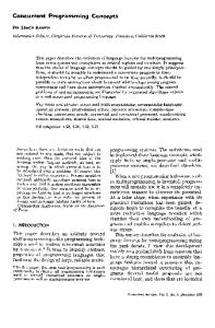
I. I NTRODUCTION Turbo codes are a class of important error correction codes due to their outstanding error correcting performance [1]. Turbo codes have been widely adopted in many wireless communication standards including 3GPP HSPA Evolution (HSPA+), 3GPP Long Term Evolution (LTE) and WiMAX. High throughput is one of the most important requirements for emerging wireless communication standards. For example, HSPA+ extends the 3G communication standards and can provide data rates up to 84 Mbps [2]. The future version of HSPA+ supporting up to 672Mbps is proposed for 3GPP Release 11 using advanced multiple antenna techniques [3][4]. As a 4G candidate, the 3GPP LTE-Advance sets its long-term goal to 1Gbps date rate. As is shown in Figure 1, a turbo decoder contains two key components: soft-input soft-output (SISO) decoders and interleavers. Maximum a posteriori (MAP) decoder is normally used as the component SISO decoder [1]. During the decoding process, the log-likelihood ratio (LLR) soft values are exchanged between component SISO decoders in an iterative way. The interleaver is a critical component for the turbo decoder to achieve good error correcting performance, by permuting the LLRs randomly between iterations and maximizing the effective free distance of turbo codes.
La(u) Lc(yP1) Lc(yS)
SISO Decoder 1
Le(u)
Le(u)
Deinterleaving
La(u) Interleaving
SISO Decoder 2
Le(u)
Interleaving
Lc(yP2) Figure 1.
The diagram of a turbo decoder.
To meet the high throughput requirements, parallel turbo decoding is necessary. One of the challenges of implementing a parallel turbo decoder is the interleaver design. Due to the randomness of interleaver, parallel turbo decoders suffer from severe memory conflict problems that restrict the maximum achievable throughput. In this paper, we propose a flexible Double-Buffer based Contention-Free (DBCF) interleaver architecture which efficiently solves the memory conflict problem for parallel turbo decoders supporting multiple standards. The contribution of this paper is twofold: firstly, this paper analyzes the statistical properties of the memory conflict problem that can be used as a guidance to design contention-free interleavers; secondly, the proposed DBCF interleaver architecture has the following features: (1) supports different parallel turbo decoding algorithms with very high parallelism such as 32 or 64; (2) supports multi-standard turbo decoders; (3) supports radix-2, radix-4 and higher radix schemes; and (4) has very low latency and hardware complexity. The paper is organized as follows. Section II introduces the background, challenges and related work. Section III analyzes the statistical properties of the memory conflicts. Section IV proposes the DBCF interleaver architecture and provides simulation results. Section V shows the hardware implementation and the synthesis results for the proposed architecture. Section VI concludes this paper. II. BACKGROUND AND R ELATED W ORK A. Parallel Turbo Decoding Algorithm Parallel turbo decoding algorithms have been extensively investigated in the literature [5][6][7][8]. Most of these parallel decoding algorithms exploited SISO-decoder level parallelism, where the codeword (with block size K) is partitioned into P sub-blocks with the size of K/P . Multiple
2011 22nd IEEE International Conference on Application-specific Systems, Architectures and Processors (ASAP)
Lc Crossbar Switch
Module 1
Input LLRs
Module 2
... Module P
Extrinsic Memory
Le SISO 1 SISO 2
... SISO P
Module 1
Crossbar Switch
Input Memory
Module 2
... Module P
Interleaver Address Generator
(a) Memory Module 1
Memory ul 2 Module conflict
Memory Module 3
Memory Module 4
Interleaver address generator & Crossbar SISO Decoder 1
SISO Decoder 2
SISO Decoder 3
SISO Decoder 4
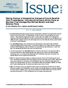
(b) Figure 2. (a) The diagram of parallel turbo decoding architecture; (b) memory conflict problem caused by the interleaver.
SISO decoders are employed and each of them operates on one of the sub-blocks, as is shown in Figure 2(a). Recently, the radix-4 SISO decoder has become more and more popular due to its high error correcting performance, low hardware complexity and its capability to support multiple standards (radix-4 decoder can decode duo-binary turbo codes used in WiMAX) [6][8][9]. Radix-4 decoders apply the one-level look-ahead concept to the trellis structure and utilize the trellis parallelism. They outperform radix-2 decoders because they can double the decoding throughput with almost the same hardware cost. In addition to SISO level parallelism and trellis level parallelism, recursion-unit level parallelism is another way to increase decoding throughput. For example, cross MAP (XMAP) SISO decoder [10][11] doubles the throughput, in which the forward recursion and backward recursion are performed simultaneously in a cross manner instead of serially executed as in the serial MAP (SMAP) algorithm. B. Challenges In a parallel turbo decoder, P SISO decoders produce multiple extrinsic log-likelihood ratio (LLR) values per clock cycle, which will access the LLR memory simultaneously after being permuted by the interleaver. Due to the randomness of the turbo interleaver, several LLR values may try to access the same memory module and cause a memory collision, as depicted in Figure 2(b). Because memory collisions can significantly degrade the decoding throughput, the memory conflict problem makes the interleaver a major bottleneck for high performance parallel turbo decoders. To solve the memory conflict problem in parallel turbo decoding systems, several dedicated contention-free inter-
leavers have been proposed. For example, the Quadratic Permutation Polynomial (QPP) interleaver in LTE and the Almost Regular Permutation (ARP) interleaver in WiMAX are two contention-free interleavers. However, for higher radix schemes such as radix-8, radix-16 or in systems with an odd number of SISO decoders, QPP and ARP interleavers are not contention-free and need a router architecture to solve memory conflicts. In addition, the interleaving algorithms in some existing standards such as UMTS/HSPA+ suffer from this severe memory conflict problem, which cannot be efficiently solved by the new dedicated interleavers [2]. In fact, the contentionfree interleaver has become the most challenging part for a high throughput multi-standard turbo decoder. Because there will be different types of networks, such as GSM, UMTS/HSPA+, LTE, and WiMAX, coexisting together for most of the decade to come, the demand for hand-held devices to support multiple standards is increasing. Therefore, building multi-standard turbo decoders is of great interest [5][12][13][14]. A flexible contention-free interleaver with low hardware complexity is an essential block for such multi-standard systems. C. Related Work Many interleaver architectures have been proposed to solve the memory conflict problem in parallel turbo decoders. These various memory conflict resolutions can be classified into three categories [14][15][16]: design-time conflict resolutions, compilation-stage conflict resolutions and run-time conflict resolutions. (1) Design-time conflict resolutions usually jointly design the interleaving algorithm and the contention-free architectures [7][9][16][17][18]. These conflict resolutions employ dedicated interleaver architectures which can resolve the memory conflict problem for certain interleaving algorithms, which, however, lack flexibility to support other interleaving algorithms or existing systems such as HSPA+ and so on. (2) Compilation-stage conflict resolutions employ certain memory mapping rules to guide the memory accesses and to avoid memory collisions [19][20][21]. For example, Tarable et al. [19] showed that for any given parallel turbo decoder and interleaving algorithm, there is always a memory mapping scheme allowing contention-free memory accessing without stalling. However, the compilation-stage solutions require many memory resources to store the memory mappings, which can significantly increase the hardware complexity. Moreover, in practical implementations, the decoders are required to support variable codeword sizes or multiple standards, however, it is impractical to find and store so many memory mappings for all the cases. Similarly, the authors of [14] proposed a solution to reduce memory conflicts using compressed permutation vectors. Although a hybrid compression approach is used, the permutation tables still require large memory area.
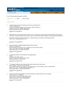
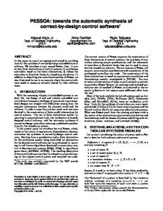
III. M EMORY C ONFLICT A NALYSIS Because the most challenging part of implementing a multi-standard turbo decoder is concurrent interleaver for HSPA+, we first analyze the statistical properties of the HSPA+ interleaving algorithm by simulation. The simulation results can provide us with the theoretical basis to design contention-free interleavers. The HSPA+ interleaving algorithm based on the column-row pseudo-random algorithm [2] was implemented. P SISO decoders and P
Memory conflict ratio
100% 80% 60% P = 32 P = 16 P =8 P =2
40% 20% 0
0
1,000
2,000
3,000
4,000
5,000
Block size (bits) Figure 3. Memory conflict ratio analysis for HSPA+ turbo code interleaver. P represents parallelism. The vertical axis represents the ratio of the number of clock cycles in which memory collision occurs to the total clock cycles needed to process a block of codeword.
Memory access probability
(3) Run-time conflict resolutions use extra flexible hardware or on-chip networks to solve the memory conflicts. We prefer the run-time solutions since the design-time and compilation-stage solutions lack the flexibility to support multiple standards and the ability to evolve with the emerging interleaving algorithms. Most importantly, the run-time solutions avoid storing the memory mapping patterns or interleaving look-up tables (LUTs) and can deliver the most efficient hardware implementations. Some related run-time solutions are briefly described below. In [22] and [23], the authors introduced a tree-based concurrent interleaving architecture (named TIBB) and an improved solution based on local buffer cells interconnected via a ring network (named RIBB), respectively. The drawbacks of these solutions lie in the high connectivity of an LLR distributor and the complex buffer structures. As the parallelism increases, the hardware complexity of the LLR distributor and buffer structures become prohibitive. In [24], the authors presented an improved architecture based on [22] and [23]. They introduced an interleaver architecture with a stalling mechanism. The main drawback of this solution is that the stalling mechanism requires the modification of the control logic of the MAP decoder which increases the design complexity and hardware cost. Moreover, the delay penalty for this stalling scheme is unacceptable for radix-4 or XMAP SISO decoder architectures. In [12] and [13], the authors introduced misalignment among memory access paths using delay line buffers. They also use FIFOs to buffer LLRs when memory conflicts occur. However, these schemes only solve the memory conflict problem for low parallelism degrees. Another drawback is that the delay penalty and hardware cost are very high. In [25] and [26], the authors proposed packet-switched network-on-chip (NoC) approaches. However, these NoC methods suffer from large delay penalty which in turn degrades the maximum throughput. Furthermore, the NoC methods require complex buffer structures to temporarily store the network packets to avoid network contention. All the solutions mentioned above have certain limitations to efficiently solve the memory conflict problems in multi-standard turbo decoders, which restrict the achievable throughput. In this paper, we propose a flexible and efficient run-time contention-free interleaver architecture based on the statistical analysis of the memory conflict problem.
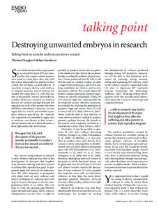
25% P = 16 P = 32
20% 15% 10% 5% 0
1 2 3 4 5 6 7 8 9 10 11 12 13 14 15 16
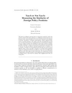
Naccess Figure 4. Probability of having Naccess simultaneous memory accesses to a memory module. Block size K=5114. Parallelism P=16 and 32. Number of memory modules M is the same as parallelism.
corresponding LLR memory modules are assumed. The block size K is set to the typical UMTS/HSPA+ block sizes (40 ∼ 5114 bits). During the parallel turbo decoding process, P MAP decoders produce P LLRs in one clock cycle which should be consumed in a timely manner by the memory to keep full the high throughput pipeline of the decoding system. Otherwise, the delay caused by frequent memory conflicts will significantly degrade the throughput. Therefore, at first, we want to know how often the memory conflicts occur. Figure 3 reveals that the HSPA+ interleaving algorithm causes severe memory conflict problems that become worse as the parallelism goes higher. P = 2 results in around 50% memory conflicts, however, when P is higher than 8, the memory conflict ratio is close to 100%. Therefore, as the parallelism goes higher, the difficulty to resolve the memory conflicts increases drastically. Although the memory conflict problem happens with such a high frequency, our simulation results show that the average number of memory accesses in one cycle is close to 1, even with high parallelism such as P = 16 or P = 32. This implies that it is possible to use buffers to smooth the memory accesses and mitigate the memory conflict problem. However, directly using a large buffer is very inefficient and the latency is unacceptable. Therefore, we further studied the memory access pattern of the HSPA+ interleaver algorithm.
Radix-4 XMAP Decoder P
FIFO PP-3 FIFO PP-2 FIFO PP-1 FIFO PP
PRN-Gen
Circular Buffer 1 Bypass Unit
Memory Module 1
LLR Memory Address
Conflict Detector
LLR Values
Priority Selector
Circular buffer Control signal Buffer Control
Conflict Detector Priority Selector
...
...
...
Buffer Router 1
To Circular Buffer To bypass unit
Pseudo-random Number Generator Buffer Router
Buffer Control
FIFO 5 FIFO 6 FIFO 7 FIFO 8
Inter-connection Network
Radix-4 XMAP Decoder 2
Conflict Detector Priority Selector
...
FIFO 1 FIFO 2 FIFO 3 FIFO 4
...
Radix-4 XMAP Decoder 1
Buffer Control
Interleaving Address Generator
PRN-Gen
Circular Buffer M Bypass Unit
Memory Module M
Buffer Router M Double-Buffer based Contention-free (DBCF) Interleaver
Figure 5.
Overview architecture of the DBCF interleaver. The right part of the figure shows the detail of the buffer router.
Figure 4 shows the probability of having Naccess simultaneous memory accesses to a memory module. If Naccess = 1, there is no memory conflict. While Naccess > 1 means that multiple LLRs try to access the same memory module simultaneously hence causing an Naccess -way memory conflict. Figure 4 shows that most of the memory conflicts are 2-way and 3-way memory conflicts. Although in the worst case, there might be more than 4 LLRs accessing the same memory module simultaneously, these cases are very rare (P rob(NCand ≥ 4) < 7%) so that on average they will not affect the system throughput. Based on this observation, a Double-Buffer based Contention-Free (DBCF) interleaver architecture is designed to resolve the memory conflict problem and enable concurrent memory accesses. Further simulation shows that the random interleaver algorithms have the similar statistical property as is shown in Figure 4, therefore, the DBCF interleaver can also be used in other random interleaving algorithms. IV. P ROPOSED DBCF A RCHITECTURE A. System Model Figure 5 shows the overview architecture of the doublebuffer based contention-free (DBCF) interleaver. Radix-4 XMAP decoders can achieve high throughput with relatively low hardware cost, however, they cause very severe memory conflict problems in parallel turbo decoders. Therefore, in this paper, we take the turbo decoder consisting of multiple radix-4 XMAP SISO decoders as an example to show the effectiveness of the DBCF architecture, however, this interleaver architecture can support any kind of parallel turbo decoder to meet throughput and area requirements. Figure 5 shows a parallel turbo decoder which contains P SISO decoders. We define the total number of the output LLRs as the parallelism parameter of the turbo decoder, denoted as PP . PP determines the extent of the memory conflict problem. The hardware implementation of the radix-
4 XMAP SISO decoder is fully pipelined. In each clock cycle, a radix-4 XMAP SISO decoder reads four extrinsic LLR values from LLR memory and then outputs four new LLR values, which should be written into the LLR memory using the interleaving addresses. Assuming four such SISO decoders are employed to achieve a preset throughput goal, we can easily determine PP = P × 4 = 16. To avoid the usage of multi-port memory, the LLR memory is partitioned into PP separated memory modules. The key components of the DBCF interleaver architecture are double buffers, which include FIFOs and circular buffers. The FIFOs are used to store the LLR values produced by the SISO decoders temporarily. Each LLR output port owns a corresponding FIFO. Each memory module is connected to a circular buffer. The circular buffers are used to store the concurrently written data values and smooth the bursty memory accesses. B. DBCF Interleaver Architecture The DBCF interleaver architecture is designed based on the statistical property of the memory conflict shown in Figure 4. As described above, it is very rare to have more than a 4-way memory conflict (< 7%). Therefore, as long as we can efficiently handle 2-way and 3-way memory conflicts, most of the memory collisions are resolved. Based on this observation, this architecture focuses on solving the most frequent 2-way and 3-way memory conflict problems. We denote the number of concurrent memory access candidates to a specific memory module per clock cycle as NCand . We define a selection parameter S which stands for the maximum number of LLR values which are chosen from NCand incoming LLR values and written into the buffer. If NCand < S, all NCand LLRs are written into the circular buffer; otherwise, if NCand > S, then only S LLRs are written into the circular buffer and the remaining (NCand − S) LLR values are rejected and put into the FIFO. In order to handle the most frequent memory conflict
problem, S can be set to 3 since NCand ≥ 4 rarely happens even for the worst case. The double-buffer architecture effectively guarantees the non-stop processing, which is crucial for turbo decoders that consist of multiple SISO decoders with high parallelism (such as the radix-4 XMAP SISO decoder). On the other hand, the usage of selection parameter S significantly reduces the complexity of interconnection in the decoding system. For instance, assuming the parallelism PP = 16, the original turbo decoding system requires a 16 × 16 full interconnection network for each memory module, however, DBCF architecture with S = 3 reduces this to a 16 × 3 interconnection network. Another important technique used in the DBCF interleaver architecture to reduce the memory conflict is sub-bank partitioning. The idea is to further partition each memory module into Nsub sub-banks which result in a total of M = PP × Nsub memory banks. More memory banks can effectively alleviate the memory conflict problem. C. Micro Architecture of DBCF Interleaver As is shown above in Figure 5, the DBCF interleaver consists of the following key components: PP FIFOs, M circular buffers, an interconnection network (ICN), an interleaving address generator (IAG), M buffer routers and M buffer bypass units. 1) Double Buffers: Double buffers includes the FIFOs and circular buffers. Each SISO decoder is connected to four FIFOs. The LLR values output from the SISO decoder are directly put into the FIFOs and wait to be read by the buffer router. Every memory module is connected to a circular buffer. Two pointers are used in the circular buffer to indicate the current reading and writing position, respectively. The sizes of FIFOs and circular buffers can be determined by simulating the corresponding interleaving algorithms and the parameters should guarantee that the FIFOs and buffers do not overflow even for the worst cases. Based on our simulation results, the required depth of the circular buffer and FIFO are very small, therefore, they can be implemented using registers so that multiple data can be written into the circular buffer simultaneously. 2) Interleaving Address Generator (IAG) and Interconnection Network (ICN): The IAG is used to generate the interleaved memory address on the fly for each output LLR value according to the interleaving law. In each clock cycle, the IAG should generate PP addresses for PP LLR values. The ICN connects all the FIFOs to the buffer routers. The interleaved memory addresses and the LLR values will be delivered to the buffer router together. 3) Buffer Router: The buffer router is the core control module for this DBCF interleaver architecture. The design goal of the buffer router is to reduce the interconnection complexity and the latency of the buffer system. The buffer router detects the memory collisions, determines which
FIFOs to read from and controls the data access to the circular buffers. The scheduling algorithm of the buffer router can affect performance of the memory conflict resolver, therefore, it should be carefully designed. 4) Bypass Unit: The bypass unit is one of the most important contributions of the DBCF architecture. The bypass unit can bypass the circular buffer and directly write the data into the corresponding memory module without extra latency if the following conditions are met: (1) the corresponding circular buffer is empty; (2) at least one LLR value attempts to access the corresponding memory module. Simulation results show that the bypass unit helps the DBCF architecture significantly reduce the latency as well as the memory requirements. D. Design Trade-offs and Simulation Results In the DBCF architecture, there are several design tradeoffs between the latency and hardware cost. First of all, larger S results in smaller latency, however, this will use more multiplexing hardware and increase the complexity of the interconnection network. Therefore, choosing an appropriate S value is important for the whole system to achieve high throughput while maintaining low hardware cost. On the other hand, sub-bank partitioning can reduce memory conflicts, however, this will introduce extra cost of the memory controller. Both of these two design trade-offs will also affect the requirements for the sizes of FIFOs and circular buffer. Table I and II show the simulation results of the proposed architecture with the parallelism of 16 and 32 (4 radix-4 XMAP SISO decoders and 8 radix-4 XMAP SISO decoders), respectively. In the tables, K is block size; PP is parallelism parameter which represents the number of LLR values produced in each time step; M is the number of memory banks; S is the maximum number of selected LLRs; C0 denotes the ideal clock cycles to decode a codeword (C0 = K/PP ); C1 denotes the actual clock cycles including buffer latency; (C1-C0) represents the penalty of the memory conflicts. Due to the limited space, only the results for the largest block size in the HSPA+ standard (K = 5114) are shown. However, this architecture works well for other block sizes. To provide a baseline reference to compare with, we measured a basic LLR router system with only a large buffer per memory bank. In every clock cycle, all the LLRs are written into the buffer if memory conflict occurs. The required buffer size is measured as well as the penalty cycles. In Table I, the first row shows that with only simple buffers, the required buffer size is 128 and the penalty caused by the memory conflict is 175 clock cycles. Since both the LLR values and the corresponding destination memory address should be stored, the area cost for the memory is very expensive. In addition, the time needed to decode a codeword is increased by 54% which significantly reduces
Table I S IMULATION RESULTS FOR DBCF I NTERLEAVER . K=5114, PARALLELISM =16. PP
Simulation parameters FIFO Buffer M S Depth Depth
Results C0
C1
Penalty (C1-C0)
16
16
1
0
128
320
495
175
16 16 16
16 32 64
3 3 3
4 3 2
12 4 5
320 320 320
332 323 322
12 3 2
Table II S IMULATION RESULTS FOR DBCF I NTERLEAVER . K=5114, PARALLELISM =32. PP
Simulation parameters FIFO Buffer M S Depth Depth
Results C0
C1
Penalty (C1-C0)
32
32
1
0
120
160
268
108
32 32
32 64
3 3
8 4
12 7
160 160
170 164
10 4
the throughput. After applying the DBCF architecture, the latency is reduced to 11 by using only a few small FIFOs and buffers. We save 87.5% of memory and reduce the penalty to 6.2%. After using the sub-bank partitioning technique, the size requirements of FIFO/buffer are further reduced. The latency penalty is reduced to less than 1%. Comparing M = 32 (each memory module is partitioned into 2 subbanks, Nsub = 2) and M = 64 (each memory module is partitioned into 4 sub-banks, Nsub = 4), we can see M = 32 is a better solution since it achieves comparable latency as for M = 64, but has lower hardware cost. With the subbank partitioning technique, we use 10.8% of original buffer resources and reduce the penalty of memory conflicts to only 3 clock cycles, which are negligible for the decoding throughput. In Table II, similar results can be observed. When M = 64 is used, the DBCF architecture can reduce the penalty to 4 clock cycles with only 5 FIFO slots and 6 buffer slots per memory module. Due to the space limitation, the simulation results for different S parameters are not shown. The simulation results match the statistical property of the memory conflicts we observed in Section III. When S = 2, the hardware cost is lower than S = 3 but with a little higher penalty (around 20 clock cycles) as we have expected. On the other hand, further increasing S to 4 or 5 does not provide much performance improvement, because the latency and the memory requirements are already reduced to very low levels for S = 3. E. Architecture Comparison with Related Work As is mentioned in Section II-C, we prefer the runtime conflict resolutions due to their greater flexibility and lower hardware complexity. Therefore, in Table III, we compare the DBCF interleaver with other run-time conflict resolutions. In this table, PP is the parallelism parameter, which is defined as the number of LLRs produced by the turbo decoder per clock cycle. As PP goes higher, a turbo
decoder has higher parallelism, thus, it is harder to efficiently solve the memory conflict problem. M denotes the number of memory banks. Given the clock frequency, the parallelism PP is the major parameter to determine the decoding throughput, therefore, to fairly compare different parallel interleaver architectures, we compare the architectures under the same PP . Table III demonstrates the buffer sizes used by different interleaver architectures. Moreover, the penalty cycles for each scheme are shown. Since different block sizes of codeword are used in different papers, we use penalty percentage as a normalized measurement to compare the performance of each solution. Penalty percentage is computed by dividing the penalty cycles by the ideal cycles needed to decode a codeword without memory collisions. Therefore, for a specific parallelism PP , smaller buffer size and smaller penalty percentage lead to a better and more efficient architecture. Compared to the related work, the DBCF interleaver has the following advantages. First, the DBCF interleaver is flexible to support both a higher radix decoder algorithm (radix4 and above) and higher parallelism (16, 32 or higher). No other work has shown the comparable flexibility and scalability. For instance, the architecture in [24] does not support the radix-4 decoder. The solution in [23] uses large amounts of buffers. The authors in [12] and [13] only show the results for parallelism of 4. In addition, the interleaver in [12] uses a large number of memory banks (24 sub-banks) which is quite inefficient. Furthermore, since each memory bank has the same buffer structure in the DBCF interleaver, it is very easy to scale the interleaver up to support higher parallelism. In contrast, the interleavers in [12][13] and [23] have poor scalability: to support different parallelism, their interconnection network should be redesigned and the parameters should be readjusted. Second, the DBCF interleaver architecture outperforms the related work with much smaller penalty percentage by using comparable buffer sizes. For example, to resolve the memory conflicts for parallelism 4/8/16, [24] employs buffer sizes of 40/80/160 and the penalty percentages are 1.1%/4%/13.6%. In contrast, this work uses buffer sizes 36/104/256 and reduces the penalty to 0.39%/0.94%/3.4%. With sub-bank partitioning, buffer sizes 40/112/224 result in even lower penalty percentages of 0.15%/0.31%/0.94% in this work. We can also notice that when using 8 memory banks to resolve to memory conflict problem for parallelism of 4, [13] has a buffer size of 367 and the penalty percentage is 5.1%. While this work uses 40 buffer slots, the penalty is as low as 0.15%. Table III also compares the maximum achievable throughput of our interleaver with the previous work. It shows that we can achieve much higher clock frequency and throughput, since our interleaver architecture simplifies the interconnection network while using less buffer resources.
Table III I NTERLEAVER ARCHITECTURE COMPARISON WITH RELATED WORK . Work
Techniques
Radix-4 support
SISO decoder type
SISO number
PP
M
Total buffers
Ideal cycles
Penalty cycles
Penalty percentage
Maximum Throughputb @6 iter.
4 8 16 4 8 16 2
4 8 16 4 8 16 2
4 8 16 4 8 16 24
200 552 3552 40 80 160 21
1279 640 320 1091 352 250 2557
174c 309c N/A 12 14 34 26c
13.6%c 48.3%c N/A 1.1% 4% 13.6% 1.0%c
39 Mbps @133 MHz 59 Mbps @133 MHz N/A 53 Mbpsd @200 MHz 88 Mbpsd @200 MHz 133 Mbpsd @200 MHz 33 Mbps @200 MHz
2
4
8
367
1279
65
5.1%
49.4 Mbps @285 MHz
1
4 8
4
16
8
32
36 40 104 112 256 224 640 704
1279
2
4 8 8 16 16 32 32 64
5 2 6 2 11 3 10 4
0.39% 0.15% 0.94% 0.31% 3.4% 0.94% 6.2% 2.5%
116 117 230 232 453 458 694 706
[23]
RIBB LLR distributor
Yes
Radix-2, SMAP (1 LLR/cycle)
[24]
Buffering, Stalling SISOs
No
Radix-2, (1 LLR/cycle)
[12]
Misalignment factor(MF) sub-banking(SB), FIFOs MF, SB, FIFOs
No
Radix-2, SMAP (1 LLR/cycle) Radix-4, SMAP (2 LLRs/cycle) Radix-4, XMAP (4 LLRs/cycle)
[13] This work
Yes
DBCF interleaver: double buffer, selection parameter, sub-banking
Yes
640 320 160
Mbps Mbps Mbps Mbps Mbps Mbps Mbps Mbps
@700 @700 @700 @700 @700 @700 @550 @550
MHz MHz MHz MHz MHz MHz MHz MHz
PP : parallelism parameter. M: number of memory banks. Ideal cycle = block length/PP . Here we list the maximum achievable throughput and the maximum achievable clock frequency reported by the previous work. c The authors did not report the penalty cycles, so the penalty cycles are estimated using the reported maximum throughput and the ideal throughput. d Throughput is linearly scaled to 6 iterations. a b
...
Priority Selector LLR Values
Comb . Logic
Sel 2
MUX S
MUX 2
...
MOD
Initial Value 2 Counter 1
Sel S
Rand S
Figure 6.
Initial Value 1
... Counter ... 2
Rand S MOD
Initial Value S Counter S
CLK
...
...
Rand 1 Rand 2
...
...
Sel 1
...
...
MUX 1
MOD
Conflict Indicators PRN Gen
Rand 2
Rand 1
Selected S LLR values
Buffer Info
Hardware diagram of the priority selector.
V. H ARDWARE I MPLEMENTATION A. Hardware Implementation of DBCF Interleaver This section presents the hardware implementation of the buffer router which is the key module in the DBCF interleaver. All the modules are fully pipelined. The buffer router consists of a parallel conflict detector, a priority selector, a random selection signal generator and a buffer control module (BCM). 1) Conflict Detector: The parallel conflict detector can be implemented by using a few compare-select units. The conflict detector can detect the memory conflict in one clock cycle and send the conflict indicators to the priority selector. 2) Priority Selector: Figure 6 shows the diagram of the priority selector. The priority selector first gets the number of empty slots in the circular buffer, which is denoted as Nbuf and then chooses up to min(S, Nbuf ) LLR data from Ncand LLR candidates. Ncand can be computed from conflict indicators. In order to maximize the overall throughput and minimize the buffer requirements, we need to keep the workloads in different buffers relatively balanced; otherwise, the circular
Figure 7.
Diagram of the efficient pseudo-random number generator.
buffer with the heaviest workload will slow down the whole decoder. An effective solution is a random selection scheme, that is, min(S, Nbuf ) winners are randomly chosen out of NCand candidates in each cycle. The combinational logic in the priority selector uses the conflict indicators and random numbers to generate the selection signals for the multiplexers. 3) Efficient Random Selection Scheme: The random selection scheme can balance the workloads among the buffers, however, the efficient hardware implementation is challenging. First, the memory access candidates cannot be predicted in advance, which means that the inputs to the multiplexers are random. Second, the selection signals for the multiplexers should be randomly generated on the fly. Third, the random numbers generated can not repeat. As is shown in Figure 7, a customized pseudo-random number generator (PRN-Gen) is designed. Because we do not need a highly random sequence, a very simple structure of PRN-Gen is designed which consists of S counters and S modular units. Although this structure is simple, when combined with the selection scheme described below, it can efficiently balance the workloads in the buffers. Let us take PP = 16, S = 3 as an example. We use three 3-bit counters counting from 1 to 7 (except 0). The initial
Table V I MPLEMENTATION RESULT COMPARISON WITH RELATED WORKa .
Table IV S YNTHESIS RESULTS OF DBCF INTERLEAVER . SISO type Interleaver # iterations Technology Voltage SISO Cores LLRs per cycle Memory banks Clock frequency [MHz] Area [mm2 ] Throughput [Mbps]
Radix-4 XMAP decoder DBCF interleaver 6 TSMC 65nm 0.9 V 4 16 16 700 0.089 453
4 16 32 700 0.138 458
8 32 32 550 0.204 694
8 32 64 550 0.215 706
Work
Methods
Technology
Area [mm2 ]
Max. fclk
[22] [23] [24] [25] [26]
TIBB RIBB Buffer+Stalling 2D Mesh NoC Butterfly NoC Benes 2N-N NoC Permutation table compression DBCF
200 nm 200 nm 130 nm 180 nm 180 nm 180 nm 40 nm
6.14 (2.82b ) 14.1 (6.47b ) 1.06 1.2 (0.61b ) 2.5 (1.28b ) 1.34 (0.68b ) 0.14 (1.29b )
150 190 200 200 302 416 350
65 nm
0.089 (0.35b )
700 MHz
[14] This Work
MHz MHz MHz MHz MHz MHz MHz
Parallelism PP = 16 for all cases; all the data are for the interleavers and do not include MAP decoders. b Technology scaling to 130 nm CMOS assuming: A ∼ 1/s2 . [8] a
values for the counters are 1, 2 and 3, respectively. Assuming the output of the i-th counter is Oi , the i-th random number RNi can be computed by RNi = Oi %NCand . These random numbers are used as the indices to select LLR values from NCand candidates. The fact that the outputs of the counters are consecutive guarantees that the generated random numbers do not repeat. Moreover, because the number NCand and the memory access candidates vary from time to time, the selected LLR values are close to random. For example, we assume that the current memory accesses come from the 3rd , 9th , 10th and 14th SISO decoders. Since there are four memory access candidates (NCand = 4), we index them like this: Cand[0, 1, 2, 3] = {3, 9, 10, 14}. S = 3 winners will be selected from these four data. Without loss of generality, we assume the current outputs of the counters are 3, 4 and 5. After mod by NCand = 4, we get the indices of the winners: 3, 0, and 1, and locate the winners: Cand[3] = 14, Cand[0] = 3, and Cand[1] = 9. Therefore, LLRs from the 14th , 3rd and 9th SISO decoders are selected for the current memory module. Simulation shows that this random selection scheme can effectively keep the workloads of the buffers balanced. In addition, it saves hardware resources due to the following reasons. First, in the example shown above, only three 3-bit counters are used which have lower hardware complexity than the linear feedback shift register (LFSR)-based random sequence generator. Second, the repetition checking and random number regenerating units are not needed, therefore, the complexity of the control logic is reduced. 4) Buffer Control Module: The buffer control module (BCM) is a finite state machine (FSM) which maintains the circular buffer. The BCM checks the availability of the circular buffer and notifies the priority selector. Then BCM gets selected data from the priority selector and writes these data in the buffer slots indicated by the write pointer. If the circular buffer is not empty, BCM pops up one data indicated by the read pointer out of the circular buffer, and writes it into the LLR memory. Meanwhile, if the bypass conditions are met, the BCM will directly deliver one data to the bypass unit, and writes other data into the circular buffer.
B. Synthesis Results and Comparison We implemented the DBCF interleaver for a multistandard turbo decoder, in which parallel radix-4 XMAP SISO decoders are employed. We synthesized the design using Synopsys Design Compiler with TSMC 65nm technology. The synthesis results are shown in Table IV, where we compare the DBCF interleaver architectures under four different configurations. We show results for 4 SISO decoders (parallelism=16) and 8 SISO decoders (parallelism=32), as well as the comparison between implementations with and without the memory sub-bank partitioning technique. Table IV shows that the DBCF interleaver architecture solves the memory conflict problem and achieves up to 458Mbps data throughput when 4 SISO decoders are running at 700MHz. For the turbo decoder with 8 radix4 XMAP SISO decoders, with the help of our DBCF interleaver, the turbo decoder can achieve up to 706Mbps data rate, which satisfies the throughput requirements of the future extension of HSPA+ standards (672Mbps). In Table V the implementation results of other published interleaver architectures that can support multiple standards including HSPA+ are shown. Because high throughput turbo decoders require high parallelism and interleavers are harder to design for such decoders, the chip area and the maximum clock frequency for parallelism of 16 are shown. Papers [12] and [13] in Table III report implementation results for the parallelism of 2 and 4 only and these two papers are not listed in this table. In Table V, the interleavers proposed by [22] and [23] require a full interconnection network and therefore have larger chip area. The solution in [24] does not support radix-4 or XMAP decoders and lacks flexibility for multiple standards. The NoC approaches in [25] and [26] require complex network structures as well as many buffers. The permutation tables in [14] occupy large memory area on chip. In contrast, the proposed DBCF interleaver shows not only flexibility, but also high performance and low hardware complexity. The maximum clock frequency obtained with the DBCF interleaver is higher than other designs. Meanwhile, the DBCF interleaver occupies the smallest die area of all designs, even when normalized for technology scaling.
VI. C ONCLUSION In this paper, we present a Double-Buffer based Contention-Free (DBCF) interleaver architecture for multistandard turbo decoders. The proposed DBCF interleaver efficiently solves the memory conflict problem for parallel turbo decoders at the execution stage and enables high throughput concurrent interleaving with low hardware complexity. Synthesis results show that the DBCF architecture can achieve better performance in terms of occupied area and the maximum frequency than the previous work. That is because the DBCF interleaver reduces the complexity of the interconnection network by fully exploiting the statistical properties of the random interleaving algorithms. Another reason is that the double-buffer architecture, combined with other efficient design aspects such as bypass unit, random selection scheme, and so on, significantly reduces the memory requirements and the complexity of the control logic. ACKNOWLEDGMENTS This work was supported in part by Huawei and by the US National Science Foundation under grants CNS-0619767, EECS-0925942 and CNS-0923479. R EFERENCES [1] C. Berrou, A. Glavieux, and P. Thitimajshima, “Near Shannon limit error-correcting coding and decoding: Turbo-codes.” in Proc. IEEE International Conference on Communications (ICC), vol. 2, May 1993, pp. 1064 –1070 vol.2. [2] 3GPP, “Technical specification group radio access network; multiplexing and channel coding (FDD), Tech. Spec. 25.212 v9.4.0 Release 9,” 2010. [3] K. Johansson, J. Bergman, D. Gerstenberger, M. Blomgren, and A. Wallen, “Multi-carrier HSPA evolution,” in Proc. IEEE 69th Vehicular Technology Conference (VTC), 2009, pp. 1 –5. [4] Nokia Siemens Networks, “Long term HSPA evolution. mobile broadband evolution beyond 3GPP release 10,” 2010. [Online]. Available: http://www.nokiasiemensnetworks.com/ sites/default/files/document/HSPA evolution white paper low res 141220.pdf [5] Y. Sun, Y. Zhu, M. Goel, and J. R. Cavallaro, “Configurable and scalable high throughput turbo decoder architecture for multiple 4G wireless standards,” in Proc. IEEE International Conference on Application-Specific Systems, Architectures and Processors (ASAP), 2008, pp. 209 –214. [6] Y. Sun and J. R. Cavallaro, “Efficient hardware implementation of a highly-parallel 3GPP LTE, LTE-Advance turbo decoder,” Integration VLSI Journal, 2010. [7] C.-C. Wong, M.-W. Lai, C.-C. Lin, H.-C. Chang, and C.Y. Lee, “Turbo decoder using contention-free interleaver and parallel architecture,” IEEE Journal of Solid-State Circuits, vol. 45, no. 2, pp. 422 –432, 2010. [8] C. Studer, C. Benkeser, S. Belfanti, and Q. Huang, “Design and implementation of a parallel turbo-decoder ASIC for 3GPP-LTE,” IEEE Journal of Solid-State Circuits, vol. 46, no. 1, pp. 8 –17, 2011. [9] J.-H. Kim and I.-C. Park, “A unified parallel radix-4 turbo decoder for mobile WiMAX and 3GPP-LTE,” in Proc. IEEE Custom Integrated Circuits Conference (CISS), 2009, pp. 487 –490.
[10] A. Giulietti, B. Bougard, V. Derudder, S. Dupont, J.-W. Weijers, and L. Van der Perre, “A 80 Mb/s low-power scalable turbo codec core,” in Proc. IEEE Custom Integrated Circuits Conference (CICC), 2002. [11] M. May, T. Ilnseher, N. Wehn, and W. Raab, “A 150Mbit/s 3GPP LTE turbo code decoder,” in Design, Automation Test in Europe Conference Exhibition, 2010, pp. 1420 –1425. [12] R. Asghar, D. Wu, J. Eilert, and D. Liu, “Memory conflict analysis and implementation of a re-configurable interleaver architecture supporting unified parallel turbo decoding,” Journal of Signal Processing Systems, vol. 60, pp. 15–29, 2010. [13] R. Asghar and D. Liu, “Towards radix-4, parallel interleaver design to support high-throughput turbo decoding for reconfigurability,” in IEEE Sarnoff Symposium, 2010, pp. 1 –5. [14] T. Ilnseher, M. May, and N. Wehn, “A multi-mode 3GPPLTE/HSDPA turbo decoder,” in IEEE International Conference on Communication Systems (ICCS), 2010, pp. 336 –340. [15] E. Boutillon, C. Douillard, and G. Montorsi, “Iterative decoding of concatenated convolutional codes: Implementation issues,” Proceedings of the IEEE, vol. 95, no. 6, pp. 1201 –1227, June 2007. [16] A. Nimbalker, T. Blankenship, B. Classon, T. Fuja, and D. Costello, “Contention-free interleavers for high-throughput turbo decoding,” IEEE Transactions on Communications, vol. 56, no. 8, pp. 1258 –1267, August 2008. [17] O. Gazi and A. Yilmaz, “Collision free row column S-random interleaver,” IEEE Communications Letters, vol. 13, no. 4, pp. 257 –259, April 2009. [18] M. Mansour and N. Shanbhag, “High-throughput LDPC decoders,” IEEE Transactions on Very Large Scale Integration (VLSI) Systems, vol. 11, no. 6, pp. 976 –996, dec. 2003. [19] A. Tarable, S. Benedetto, and G. Montorsi, “Mapping interleaving laws to parallel turbo and LDPC decoder architectures,” IEEE Transactions on Information Theory, vol. 50, no. 9, pp. 2002 – 2009, Sept. 2004. [20] A. Giulietti, L. van der Perre, and A. Strum, “Parallel turbo coding interleavers: avoiding collisions in accesses to storage elements,” Electronics Letters, vol. 38, no. 5, pp. 232 –234, Feb. 2002. [21] C. Chavet and P. Coussy, “A memory mapping approach for parallel interleaver design with multiples read and write accesses,” in Proc. IEEE International Symposium on Circuits and Systems (ISCAS), 2010, pp. 3168 –3171. [22] M. Thul, N. Wehn, and L. Rao, “Enabling high-speed turbodecoding through concurrent interleaving,” in Proc. IEEE International Symposium on Circuits and Systems (ISCAS), vol. 1, 2002, pp. 897–900. [23] M. Thul, F. Gilbert, and N. Wehn, “Concurrent interleaving architectures for high-throughput channel coding,” in Proc. IEEE International Conference on Acoustics, Speech, and Signal Processing (ICASSP), 2003, pp. 613–16 vol.2. [24] F. Speziali and J. Zory, “Scalable and area efficient concurrent interleaver for high throughput turbo-decoders,” in Proc. Euromicro Symposium on Digital System Design (DSD), 2004, pp. 334 – 341. [25] C. Neeb, M. Thul, and N. Wehn, “Network-on-chip-centric approach to interleaving in high throughput channel decoders,” in Proc. IEEE International Symposium on Circuits and Systems (ISCAS), May 2005, pp. 1766 – 1769 Vol. 2. [26] H. Moussa, O. Muller, A. Baghdadi, and M. Jezequel, “Butterfly and Benes-based on-chip communication networks for multiprocessor turbo decoding,” in Design, Automation Test in Europe Conference Exhibition (DATE), 2007, pp. 1 –6.