The 6th International Conference on Ubiquitous Robots and Ambient Intelligence (URAI 2009)
Guided Path Planning for Proximity Location Sensors Sunglok Choi, JaeYeong Lee, Yu-Cheol Lee, Seung-Hwan Park, and Wonpil Yu Robot Research Department, ETRI, Daejeon, Republic of Korea {sunglok, jylee, yclee, sinkyv, ywp}@etri.re.kr
Keywords— Path Planning, Proximity Sensor, Tag, RFID, Barcode, A*
localization [3], [2], [1], not path planning. This paper enumerates several approaches to generate the guided path considering tags in section 3. Two kinds of maps, a road map and grid map, were considered for the guided path. Especially, two approaches on the grid map are described. They utilize a existing path planner on the grid map without modification, but just use the reformed map. Two approaches were compared on experiments, which are presented in section 4. At first, it is useful to analyze how to place tags, which is described in the next section.
1. Introduction
2. Tag Placement
A proximity sensor is a device to detect the presence of nearby objects, which is used to estimate position of a robot. RFID and barcode (Figure 1) are popular proximity sensors in robotics. They consists of tags and reader which can detect the tag and identify its ID. Generally, the tags are distributed in the operating space as landmarks and a robot is equipped with the reader. The robot can estimate its position when the robot is near a tag and the reader recognizes it. Some RFID readers (usually with active-type tags) provide long detection range with measurement of signal strength. They are enough to apply trilateration or other complex methods [1]. However, many proximity sensors just identify tags within very small range, (less than 0.3 meters). A robot with them regards its position as location of detected tags on the map [2], [3].
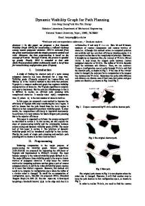
Tags can be distributed in various manners, which can be categorized into road style, uniformly distributed style, and their mixture (Figure 2). One extreme, road placement, concentrates tags on expected trajectory or workspace. On the other hand, uniform placement distributes tags all available area. The road placement uses tags more frequently than the uniform placement, but a user needs to know or define trajectory of a robot. The trajectory is related with purpose or operation of the robot, that is, the road placement is coupled with many external factors. The road placement needs less tags than the uniform placement when the tags are installed with same interval. It is economic. However, the uniform placement is relatively safer when the robot can be out of the predefined area. There are much more placements than Figure 2, which intend to concentrate or spread tags. The objectives of two extremes can be averaged through mixing them together, which is mixture placement. A number of mixture is possible. Figure 2(c) is simple mixture of the road and uniform alignment. Figure 2(d) is more complex mixture, which aims for building a net or lattice. Tags are focused to construct a net as like roads, but the net covers the whole space as like the uniform placement. Users can scatter tags without any rule (Figure 2(c, e)), or align tags regularly (Figure 2(a, b, d, f)). The alignment rule is useful to make a map, which contain location of tags, but tag installation can be harder to keep the rule. Type of tag placements affects how to navigate on the given environment with the proximity sensor. A robot does not need to consider location of tags when the tags are the uniformly distributed (Figure 2(d, e, f)). The robot will hit tags probabilistically. However, it is necessary to follow tags when the tags are located only on the predefined area (Figure 2(a, b, c)). A path planner is required to generate a path on tags for moving on the tags. Two different navigation policies are presented in Figure 3.
Abstract— A robot can estimate its position by detecting RFID or barcode tags. The tags and their reader have small detecting range less than 0.3 meters, and provide position of the robot through proximity. It is difficult to distribute the tags all over the space, so a path planner needs to guide paths toward tags to hit the tags more frequently. This paper enumerates methods to generate the guided path on the road map and grid map. Especially, two approaches on the grid map were described in detail and analyzed in experiments.
(a) Tags on the Floor Fig. 1.
(b) A Barcode Tag
Example: Barcode Tags for Localization
A path planner needs to generate a guided path toward tags when the robot moves to the goal with a small range proximity sensor. The guided path can make the robot detect tags more frequently than the shortest path. Many researches related with the proximity sensor have been focused on This work was supported partly by the R&D program of the Korea Ministry of Knowledge and Economy (MKE) and the Korea Evaluation Institute of Industrial Technology (KEIT). (2008-S-031-01, Hybrid u-Robot Service System Technology Development for Ubiquitous City)
The 6th International Conference on Ubiquitous Robots and Ambient Intelligence (URAI 2009)
(a) A* Shortest Path Planner
Fig. 2.
Three Kinds of Tag Placement
(a) Follow the Tags Fig. 3.
(b) Guided Path Planner 1 and 2
(b) Ignore the Tags
Two Kinds of Navigation Policy
Fig. 6.
Result 1 (Red: Generated Path, Blue Circle: A Robot)
ones. The weight of road can be quantified as 3. Guided Path Planning w= Generally, path planning is graph search because the given space is usually represented in graphs. A reactive path planner is an only exception (e.g. potential field and bug method). A visibility map [4], Voronoi diagram [5], and road map [6] are a general form of graphs. A tree data structure, used by RRT [7] and its variants, is also a constrained form of graphs, which is an acyclic graph to keep hierarchy of the tree. Moreover, a grid map is regarded as a graph in path planning. Each cell is a vertex, which is connected its free adjacent cells. The grid map is a dense type of graph. Two kinds of graphs can describe tags aligned by the road placement (Figure 4). A road map is comprised in vertices and edges. A vertex represents a joint of roads or key point, and a edge expresses a piece of roads. A grid map is a multidimensional array whose cell indicates whether it is occupied or not. Each cell can contains not only occupancy, but also its certainty probability or moving cost. The road by tags can be advantaged by less moving cost, which causes a guided path toward tags. The road map usually needs less vertices than the grid map, but it is difficult to express a complex or curved road. The grid map constructs more dense graph, and some of cells seem wasteful. However, it simply represents graph structure, and it is easy to describe curvature and very complex roads. It is intrinsic how to construct the road map, but several approaches are possible to express roads on the grid map. The first approach is to assign less moving cost to cells on tags. Figure 5(b) presents an example whose occupied cells (black) have infinite cost. The free cells (gray) have 1 cost value, but the cells on tags (white) has less cost than the free
Croad , C f ree
(1)
where C f ree and Croad are cost values on free cells and roads, respectively. For example, the weight of road in Figure 5(b) is 0 if the cost on roads is 0. The second approach is to assign infinite cost to free cells except roads. Figure 5(c) shows an example. It is an extreme case of the first approach, whose weight of road is 0 regardless of cost value on roads. 4. Experiments Two approaches were evaluated at the lobby in Bucheon Technopark 4th Complex, whose map with barcode tags are presented in Figure 6(a). The barcode tag is 1.75-by-1.75 centimeters, and its reader can detects it when it is within 6 centimeters. About 10 thousands tags were distributed in the road placement due to economic reason. The roads comprised three lines (Figure 1), and their interval was 20 centimeters. The start and goal point was selected as the nearest point on the roads. A* was utilized as a search algorithm on the grid map, whose heuristic was diagonal distance with Fudge heuristic [8]. The mean filter was also used to generate a smooth path. Figure 6 and Figure 7 present representative generated paths by two approaches. Both approaches usually gave guided paths as like Figure 6(b), but the first approach sometimes failed to guide the path on the roads as like 7(a). This unguided path was resulted from heuristic of A*, which compensated disadvantage of cost value. The second approach seems better since it always forces the guided path.
The 6th International Conference on Ubiquitous Robots and Ambient Intelligence (URAI 2009)
(a) The Map with Tags (Blue: Tags) Fig. 4.
(c) Grid Map (Gray: Significant Cost Value)
A Example Map and Two Kinds of Maps for Guided Path
(a) The Map with Tags (Blue: Tags) Fig. 5.
(b) Road Map (Orange: Vertex, Green: Edge)
(b) The Cost Map of Approach 1
(c) The Cost Map of Approach 2
The Given Map (White: Empty, Black: Occupied) and Its Cost Maps (White: 0, Gray: 1, Black: ∞)
forward and intrinsic, but planning on the grid map needs to be investigated more. Two approaches on the grid map is proposed and analyzed in real experiments. The second approach performed better results, which marks all cells as occupied except tags. Acknowledgement The authors would like to thank Jaeyong Seo (Microrobot Co.) for supporting barcode tags and reader. (a) Guided Path Planner 1
References
(b) Guided Path Planner 2 Fig. 7.
Result 2 (Red: Generated Path, Blue Circle: A Robot)
5. Conclusion This paper enumerates three types of tag placements: the road, uniform, and mixture placement. The road placement pursuits efficiency, but the uniform placement aims for completeness. A path should be generated on the given road when the tags are aligned as the road placement. Two kinds of road representation are described: the road map and grid map. Path planning on the road map is straight-
[1] D. Hahnel, W. Burgard, D. Fox, K. Fishkin, and M. Philipose, “Mapping and localization with RFID technology,” in Preceedings of the IEEE International Conference on Robotics and Automation (ICRA), 2004. [2] J. Huh, W. S. Chung, S. Y. Nam, and W. K. Chung, “Mobile robot exploration in indoor environment using topological structure with invisible barcodes,” ETRI Journal, vol. 29, pp. 189–200, 2007. [3] S. Park and S. Hashimoto, “Indoor localization for autonomous mobile robot based on passive RFID,” in Proceedings of the IEEE International Conference on Robotics and Biomimetics, 2009. [4] N. J. Nilsson, “A mobile automation: An application of artificial intelligence techniques,” in Proceedings of the International Joint Conference on Artificial Intelligence, May 1969. [5] O. Takahashi and R. J. Schilling, “Motion planning in a plane using generalized voronoi diagrams,” IEEE Transactions on Robotics and Automation, vol. 5, no. 2, pp. 143–150, April 1989. [6] L. E. Kavralu, P. Svestka, J.-C. Latombe, and M. H. Overmars, “Probabilistic roadmaps for path planning in high-dimensional configuration spaces,” IEEE Transactions on Robotics and Automation, vol. 12, pp. 566–580, 1996. [7] J. J. Kuffner and S. M. LaValle, “RRT-Connect: An efficient approach to single-query path planning,” in Preceedings of the IEEE International Conference on Robotics and Automation (ICRA), April 2000, pp. 995– 1001. [8] A. Patel, “Amit’s A* Pages,” http://theory.stanford.edu/∼amitp/ GameProgramming/.