FPGA Implementation of a Configurable Cache/Scratchpad Memory with Virtualized User-Level RDMA Capability George Kalokerinos, Vassilis Papaefstathiou, George Nikiforos, Stamatis Kavadias, Manolis Katevenis, Dionisios Pnevmatikatos and Xiaojun Yang Institute of Computer Science, FORTH, Heraklion, Crete, Greece – member of HiPEAC {george,papaef,nikiforg,kavadias,kateveni,pnevmati,yxj}@ics.forth.gr
Abstract—We report on the hardware implementation of a local memory system for individual processors inside future chip multiprocessors (CMP). It intends to support both implicit communication, via caches, and explicit communication, via directly accessible local (”scratchpad”) memories and remote DMA (RDMA). We provide run-time configurability of the SRAM blocks near each processor, so that part of them operates as 2nd level (local) cache, while the rest operates as scratchpad. We also strive to merge the communication subsystems required by the cache and scratchpad into one integrated Network Interface (NI) and Cache Controller (CC), in order to economize on circuits. The processor communicates with the NI in user-level, through virtualized command areas in scratchpad; through a similar mechanism, the NI also provides efficient support for synchronization, using two hardware primitives: counters, and queues. We describe the block diagram, the hardware cost, and the latencies of our FPGA-based prototype implementation, which integrates four MicroBlaze processors, each with 64 KBytes of local SRAM, a crossbar NoC, and a DRAM controller on a Xilinx-5 FPGA. One-way, end-to-end, user-level communication completes within about 30 clock cycles for short transfer sizes.
I. I NTRODUCTION Memory hierarchies of modern multicore computing systems are based on one of the two dominant schemes –multilevel caches, or directly-addressable local “scratchpad” memories. Caches transparently decide on the placement of data, and use coherence to support communication, which is especially helpful in the case of implicit communication, i.e. when we do not know in advance which input data will be needed, or who last modified them. On the other hand, caches lack deterministic response time, they make it hard for the software to explicitly control and optimize data locality and transfers in the cases when it can intelligently do so, and coherent caches scale poorly to over hundreds of processors. Scratchpads are popular in embedded [1] and special purpose systems with accelerators [2][3], because they offer predictable performance which is required by real-time applications; they also offer scalable general-purpose performance by allowing explicit control and optimization of data placement and transfers. Explicit communication uses remote direct memory accesses (RDMA); it is efficient, and it becomes possible in the cases when the producer knows who the consumers will be, or when the consumer knows its input data set ahead of time. Recent
advances in parallel programming and runtime systems [4][5] allow the use of explicit communication with minimal burden to the programmers, who merely have to identify the input and output data sets of their tasks. Our goal is to provide unified hardware support for both implicit and explicit communication. To achieve low latency, we integrate our mechanisms close to the processor, in the upper cache levels, unlike traditional RDMA which is implemented at the level of the I/O bus. We provide configurability of the local SRAM blocks that are next to each core, so that they operate either as cache or scratchpad, or as a dynamic mix of the two. Configurability is at run-time, to allow different programs with different memory requirements to run on the same core, or even different stages of a program to adapt the underlying memory to their needs. We also strive to merge the hardware required by the cache and scratchpad into one integrated Network Interface (NI) and Cache Controller (CC), in order to economize on circuits. To this end, we propose a simple, yet efficient, solution for cache/scratchpad configuration at run-time and a common NI that serves cache and scratchpad communication requirements. The NI receives DMA commands and delivers completion notification in designated portions of the scratchpad memory. This allows the OS and runtime systems to allocate as many NI command buffers as desired, per protection domain, thus effectively virtualizing the NI, while providing user-level access to its functions, so as to drastically reduce latency. Relative to traditional NI’s, which used their own, dedicated memory space, we improve SRAM utilization by sharing the same SRAM blocks between the processor and the NI, while preserving high-throughput operation by organizing these SRAM blocks as a wide interleaved memory. The scratchpad space can be allocated inside the L1 or L2 caches and consequently the NI is brought very close to the processor, thus reducing latency. Our NI also offers fast messages, queues, and counters, as synchronization primitives, to efficiently support advanced interprocessor communication mechanisms. We assume Global Virtual Addresses and Progressive Address Translation [6]. This paper describes (in section III) the hardware implementation, through FPGA prototyping, of such a configurable level-2 cache/scratchpad, with an integrated CC/NI controller,
c IEEE Proc. Int. Conf. on Embedded Comp. Systems: Architectures, Modeling, Simulation – IC-SAMOS, Greece, July 2009; pp. 149-156
2 offering virtualized user-level RDMA and synchronization primitives (an overview of the architecture is given in section II). We describe the block diagram and we report on the hardware cost, showing that the merged cache plus scratchpad uses 20 percent less hardware than the two separate systems, not counting the economy resulting from the better utilization of the SRAM space. Performance-wise, one-way, end-to-end, user-level communication completes within about 30 clock cycles for short transfer sizes; we analyze the components of this communication latency (section IV). Related work, conclusions, and future work appear at the end of the paper. II. A RCHITECTURE OVERVIEW Our proposed architecture targets chip multiprocessor systems with tens or hundreds of processor cores: each core has at least two levels of private caches and communicates with shared memory using Global Virtual Addresses [6]. This section describes run-time configuration of the local SRAM blocks as cache and/or scratchpad. We explain how scratchpad memory can be used to support virtualized NI command buffers, and present our hardware synchronization primitives. A. Run-time configurable Scratchpad Scratchpad space in our scheme is declared as a contiguous address range and corresponds to some cache lines that are pinned (locked) in a specific way of the cache, i.e. cache line replacement is not allowed to evict (replace) them. Scratchpad areas can be allocated inside either L1 or the L2 caches. Most applications seem to require relatively large scratchpad sizes, so the L2 array is a more natural choice. Moreover, L2 caches offer higher degree of associativity, hence more interleaved banks. Although L2 latency is higher than L1, the performance loss due to this increased latency is partly compensated in two ways: (i) our L2 and scratchpad supports pipelined accesses (read or writes) at the rate of 1 word (at random address) per clock cycle; (ii) configurable parts of the scratchpad space can be cacheable in the (write-through) L1 caches (our current prototype does not yet implement L1cacheable scratchpad regions). As in [6], owing to the use of progressive address translation, caches and scratchpad operate with virtual addresses, and a TLB need to be consulted only when going out of the node (out of L2), through the NI, to the NoC. In lieu of the processor-TLB, our architecture has a small table called Address Region Table (ART) which marks contiguous address ranges either as cacheable or as scratchpad and provides access rights (protection) for each of them. Every scratchpad word must be allocated within a cache-line whose low-order bits (cache index) are compatible with the scratchpad address. On the other hand, in the multi-way set-associative L2, the above scratchpad can be freely allocated into any of the cache ways; the ART identifies the way that is used. Identifying scratchpad regions in this way using the ART has the following advantage: a single ART entry can describe a large, contiguous scratchpad region; then all tags of this region, in L2, are freed (except for a single “locked” bit, used during cache accesses, when
comparing all tags in a set, to tell the comparators to ignore this way); in this way the NI can use the tags for its own purposes (communication state and meta-data). B. Virtualized user-level DMA NI command buffers are DMA control areas which are allocated upon user software demand and reside in normal scratchpad regions. These buffers share the same ART entry with normal scratchpad and the distinction is made using a special bit (cache-line state), located inside tag control bits (set upon allocation). Any user program can have dedicated NI command buffers (DMA registers) in its scratchpad region; this allows a low-cost virtualized DMA engine where every process/thread can have its own resources. To ensure protection of the virtualized resources, we also utilize permissions bits in the ART and demand the OS/run-time system to update the ART appropriately on context switches. Moreover, the inherent support for dynamic number of DMAs at run-time, promotes scalability and allows the processes to adapt their resources on the program’s communication patterns that might differ among different stages of a program. DMAs are issued as a series of store instructions – to provide the arguments: opcode, size, source and destination address – destined to words within a marked line, that gradually fill DMA command descriptors, possibly out-of-order. The NI uses a command protocol to detect command completion and inform the DMA engine that a new command is present. When serving DMAs, the NI generates packets, along with their customized lightweight headers, that belong to one of the two primitive categories: Write or Read. The NI carefully segments the DMAs into smaller packets when they exceed the maximum network packet size. Additionally, the NI offers the cache controller a dedicated set of command registers in order to serve cache needs for write-backs upon replacements and fills upon misses: the same mechanisms, and the same Read and Write packets, serve DMA transfers as well as cache operations. C. Advanced Interprocessor Communication (IPC) Primitives In order to achieve more efficient communication between processors we provide some advanced NI features that offer additional flexibility to the programmers. We implement Remote Stores to scratchpad regions of remote processors, in order to optimize the latency of single-word data transfers [7]; the ART can identify address ranges as remote. We also provide Remote Queues as an appropriate level of abstraction for multiprocessor synchronization [8] where fast multi-word Messages, e.g. data up to cache-line size, from multiple sources can perform atomic Remote Enqueues. Queues are hosted inside scratchpad regions and their configuration (size and pointers) can be programmed in special control lines, marked in the tags. Messages are initiated through NI command buffers, already used for DMAs, where data are provided directly by the processor – no source address is needed. Finally we implement Counters, also hosted in scratchpad space, as a primitive to support RDMA completion detection,
c IEEE Proc. Int. Conf. on Embedded Comp. Systems: Architectures, Modeling, Simulation – IC-SAMOS, Greece, July 2009; pp. 149-156
3
XBAR
TILE 1
CPU
ART
$
T TILE 2
TILE 3 DDR CNTRL
L1
$
LM
L2 NI
L2 CNTRL
TILE 0
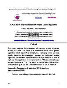
NoC Fig. 1.
FPGA Prototype Block Diagram
barriers, and other synchronization primitives. Counters are initialized with a value (transfer size in bytes) and trigger writing to notification addresses when they expire (reach zero). The software can specify an acknowledgement address in NI commands to identify a counter that will gather all partial acknowledgements for DMA segments; acknowledgement addresses are allowed to be “null” to deactivate the mechanism. III. FPGA- BASED P ROTOTYPE AND I MPLEMENTATION Our hardware prototype is implemented in a Xilinx Virtex5 FPGA using four MicroBlaze soft-cores as processors. The processors are 32-bit, in-order, single outstanding memory access, and have a traditional 5-stage pipeline that also supports single-precision floating point operations. Each processor tile has a private L1 data cache and a private configurable L2 cache/scratchpad memory tightly-coupled with our NI. At the moment there are no instruction caches (in progress) and the code is fetched from instruction scratchpads connected directly to the processors. The prototype is also equipped with a 256MByte DDR2 SDRAM which is used as main memory and is shared between tiles. Communication between tiles and the off-chip DDR memory controller is achieved through a 32bit, 5-port input-queued crossbar switch (XBAR) that applies round-robin scheduling and has a latency of 3 clock cycles under light load. The prototype does not yet implement cache coherence. The operating clock frequency of the system is currently 75MHz and its block diagram along with the major components is illustrated in Figure 1. A. Configurable Cache/Scratchpad Memory Our prototype implements, in every tile, a private L1 cache and a private configurable L2 cache/scratchpad; these are smaller than one would expect in a CMP, due to limited resources in the FPGA. Usual L1 caches range from 16 to 64 KBytes, 2 to 4 way set associative, with 64-byte lines. Our implementation has scaled down the L1 caches to 4KB, directmapped, with 32-byte cache-lines. Our L1 cache is writethrough, with 64-bit-wide refills, a single-cycle hit latency, and follows “no-allocate” policy on store misses. L2 caches, on the
other hand, are usually much larger, with sizes beyond 1MB, associativity up to 16-ways, and line size up to 128 bytes. Scaling down again, we have designed a 64 KB, 4-way setassociative write-back L2 cache with 32-byte lines and 64-bit wide data banks. Our L2 cache controller supports multiple hits under a single miss in order to minimize the processor idle time, and has a single-entry deferred-write buffer which supports bypassing. The L2 controller serves write-backs and fills on misses, using the transfer primitives of the tightlycoupled NI as described in the next subsection. The key component that allows us to configure and use parts of the L2 cache as scratchpad is the Address Region Table (ART); its function is similar to a traditional TLB, but it provides only protection and type information –not physical address translation– hence the ART can be smaller than a TLB (and have no misses), because it can describe potentially huge regions of the address space using a single entry. The ART classifies each memory access as one of: (i) cacheable, (ii) scratchpad, (iii) remote scratchpad, or (iv) tag access (used to access and set lock bits in L2). The ART is placed in parallel with the L1 cache, and is probed on every memory access from the processor. A copy of the ART is also used by the outgoing and incoming NI. Our current prototype uses only physical addresses, so we replaced the ART, for the moment, with a static, hardwired mapping: each L2 data and tag array in our system has a unique physical address (nodeID and way number are encoded in the MSBs of the address). An important issue for the efficient use of scratchpads and their associated DMAs is the available memory bandwidth. Scratchpad areas in our design are hosted inside the L2 memory banks and the NI accesses them at high rate when performing DMAs. On the other hand, the default set-associative cache organization requires all the ways to be probed in parallel, thus limiting the available memory bandwidth for the NI and causing conflicts. In order to reduce the memory bandwidth required by the typical L2 cache operation and use it more efficiently for NI operations, we implement an L2 wayprediction scheme at the L1 level – the earliest possible stage where an L2 cache access is decided. Many way prediction schemes use the program-counter (PC) [9] to predict a cache way that will likely hit. In contrast, we generate short signatures, using the address tag bits, and perform partial matches [10]. Our scheme uses a table, placed next to L1, that keeps 8-bit signatures for every L2 cache line. The 8-bit signatures are generated by applying bitwise XOR in the address tag bits. Our simulations revealed 99% prediction accuracy and significant improvement over the case where the 8 LS bits of the address tag are used; 4-bit signatures yield lower accuracy. Our signatures may produce false positives, but not false negatives. Comparing the signatures with the actual address is done in parallel with L1 tag matching, and a bit-mask is generated to indicate the L2 ways that may hit; it is used upon L1 read misses and on all writes (L1 is writethrough). Upon L1 miss, the L2 controller probes the possible ways sequentially to find a hit or declare a miss. The signature table is updated when L2 misses and evictions occur.
c IEEE Proc. Int. Conf. on Embedded Comp. Systems: Architectures, Modeling, Simulation – IC-SAMOS, Greece, July 2009; pp. 149-156
4
Fig. 2.
Cache/Scratchpad Memory
Our sequential L2 access pattern allows tag arrays to be placed together, “one under the other”, in a single memory block, thus economizing on the FPGA memory resources that are offered in 4 KB blocks. Valid, Locked, and Dirty bits are maintained in a separate, dual-ported memory block, where the control bits of all cache-lines that belong to a set are kept together, in the same memory word. Maintaining all control bits together allows fast cache-line replacement decisions, while the second port allows setting the “dirty” bit on back-toback stores and loads without blocking (L1 is write-through thus stores in L2 are very frequent). Our replacement policy is “random” among non-locked (non-scratchpad) lines. Our L2 provides a path for the processor to read and write the tags as random “data” rather than addresses, thus allowing the processor to set the lock and other control bits that are required for the NI operation; the ART controls which tag regions a process is allowed to access, and which ones not. The L2 data memory is organized in four independent ways, with two interleaved memory banks per way (a total of eight memory banks), and offers two architectural ports, reaching a peak throughput of 128 bits/cycle. The choice of two banks per way helps reducing the conflicts when accesses from the processor and the NI happen to target the same way, e.g. scratchpad accesses concurrently with DMA operations. The memory ports are shared between incoming and outgoing NI on one hand, and the processor on the other; when there is no processor access the two NI paths can use both ports. Although, the available memory bandwidth allows more than two architectural ports, the hardware cost of the required multiplexing circuits is high, and the bank conflict and arbitration logic creates complex and slow circuits. Our design benefits from the dual-ported memory blocks that the FPGA offers (by default) in order to economize on multiplexing
circuits: we emulate 8 single-ported banks using 4 dual-ported RAM blocks, by artificially refusing to serve simultaneous accesses to a “would-be” single bank. Figure 2 presents the datapath and the pipeline of our design. All memory accesses arriving from the processor are checked against the ART regions and probe the L1 cache and way prediction table in parallel. Cache hits are served normally, while misses, scratchpad, and tag accesses are forwarded to L2, along with all the control information: type of access and way mask (prediction for cacheable or onehot for scratchpad). Upon reaching L2, the requests pass the arbitration stage and access tags and data as many times as required by way prediction and full-tag matches. Scratchpad loads have a latency of 4 clock cycles while stores take 3 clock cycles to be committed to memory. The observed processor latency for stores is 1 clock cycle, since all stores are “posted” and pipelined in our design. B. NI Operation and Mechanisms The NI is tightly-coupled to the L2 cache and serves all data transfers from/to tile’s configurable memory and the NoC. The block diagram of the NI is shown in Figure 3. The outgoing path arbitrates between all sources of outbound traffic and generates every outgoing packet. The incoming path serves inbound traffic, stores data in-place and, depending on the type of traffic (cache or DMA), performs all the necessary steps. NI Command and Control Lines are allocated on software demand in cache lines inside scratchpad areas: some of the free tag bits of locked cache lines distinguish between four types of such lines: •
Normal Memory: normal scratchpad memory without side-effects.
c IEEE Proc. Int. Conf. on Embedded Comp. Systems: Architectures, Modeling, Simulation – IC-SAMOS, Greece, July 2009; pp. 149-156
5 from L1
Data Tags
Cmd Wr Buffer
AckQ
Pending CmdQ
Rem St Buffer from L2 cntrl
from net
Incoming NI Compl Monitor
Arbiter
L2
A R T
Cache Request
Outgoing NI Fig. 3.
to net
RDMA Engine
completion, every descriptor should contain its own size (in bytes) inside the word at offset zero. The first word of every descriptor contains the following fields: (i) 8-bits descriptor size (bytes), (ii) 8-bit opcode (copy/message), (iii) 16-bit copy size (bytes - max 64 KBytes), used only when opcode is copy. Copy descriptors contain three mandatory arguments: (a) 32-bit source virtual address, (b) 32-bit destination virtual address, and (c) 32-bit acknowledgement virtual address. Message descriptors contain two mandatory arguments –(a) 32-bit destination virtual address and (b) 32-bit acknowledgement virtual address– and up to five optional words that constitute the actual payload of the message. The NI uses its copy of the ART to distinguish local source addresses (write-RDMA) from remote sources addresses (read-RDMA), to validate (for protection purposes) the address arguments, and to provide routing information for them through the NoC (our current prototype only uses physical addresses, hence routing information is hardwired in the FPGA design).
Additionally, the NI serves incoming RDMA-Read requests. In order to meet the buffering requirements for the incoming requests, without dedicating a separate memory block, we require the software to allocate a Read Service Queue, in the form of a normal queue, and then assign its address to a special register that is dedicated for this purpose.
Completion Monitor and Write Buffer The NI includes a monitor circuit for Command lines, and uses the descriptor size to detect completion of commands, even in the presence of out-of-order stores, but assuming single-write of each byte inside the command line. The monitor is activated when stores arrive to cache-lines marked as Command, and a bitmap of the already completed bytes is formed and updated. The bitmap is kept in the free tag bits of these lines and when the number of consecutive “ones” matches those implied by the descriptor size, then command completion is triggered. Upon completion, the address of the command buffer is enqueued in the Pending Command Queue in order to be served by the outgoing NI. Since the completion bitmap is kept in the tags of each associated cache line, the monitor circuit supports interleaved command issuing (in different command buffers) offering full virtualization to the software (e.g. when a thread is swapped out while composing a command). All NI commands are stored inside scratchpad memory and thus the outgoing NI has first to read the descriptor contents, word-by-word from the memory, and then start serving it. The reading step wastes memory bandwidth and increases latency. To reduce latency, in the common case where issues are not back-to-back, we provide a Command Write Buffer, which is one-cache-line wide, and is placed in parallel with the memory. When the buffer is free, it holds a partiallycompleted command, monitors its progress, and detects its completion. The NI serves commands in this buffer faster, since all descriptor arguments are immediately available. The allocation policy of the write buffer is first-come-first-served; deallocation happens when the NI completes serving it.
NI Commands and Protocol Commands to the NI are issued as a series of stores to the data part of Command lines. Our protocol defines two types of commands: (i) Copy and (ii) Message. Copy descriptors are DMAs and have a fixed size of four 32-bit words, while messages have any size up to one cache-line (eight 32-bit words in our prototype). In order to achieve automatic command
Remote Stores Store instructions to addresses identified by the ART as being remote scratchpad, result in network packets carrying write requests, identical to RDMA or message packets (of size 1 or more words). Stores marked as “remote” are kept in the Remote Store Buffer, and served by the outgoing NI engine as soon as it is free. A write-combining mechanism is
•
•
•
Command: they are the analogous of (virtualized) I/O command registers, and buffer RDMA message send requests. They are monitored by the command completion hardware, which triggers the outgoing DMA engine. Queue: this cache line contains 4 pointers in its data words –base, bound, head, tail– describing a queue implemented in a circular buffer, where that buffer is allocated by software somewhere in the scratchpad outside the cache line itself. Incoming write packets (e.g from remote store, message send, or RDMA) are treated by the NI depending on the type of their destination-address line: for normal-memory lines, their contents are written there; for queue-type lines, the packets are enqueued inside the circular buffer, and the NI updates the tail pointer. The head pointer is updated under software control. Counter: these lines contain a 24-bit counter in the free tag part, and notification addresses (one, for the moment) in the data part. Writes to the counter-line address increment the counter by the (signed) contents of the (single-word) packet. Upon reaching zero, the counter triggers the transmission of notification packets to the notification addresses.
c IEEE Proc. Int. Conf. on Embedded Comp. Systems: Architectures, Modeling, Simulation – IC-SAMOS, Greece, July 2009; pp. 149-156
6 implemented: if multiple remote stores to adjacent addresses arrive before some previous ones have departed, they are all coalesced in a single, multi-word-write packet. Completion Notifications We assume multi-path (adaptive) network routing, hence the multiple packets of a large RDMA may arrive out-of-order; this is not a problem, given that each of them carries its own, correct destination address, but RDMA completion detection must now be performed by counting the number of bytes that have arrived (our network never generates duplicates). We implement counters to support RDMA completion notification. Each session, of one or more RDMA operations, uses one counter (allocated by software). The issuer increments that counter by the total size of all RDMA transfers. Every RDMA packet carries the counter address in its acknowledgement field; upon successful write, the counter is decremented by the packet size. Assuming that the counter started at zero, when it reaches zero again we know that all bytes have arrived. As mentioned above, when the counter reaches zero the NI automatically sends notification packets to its pre-configured notification addresses (which may happen to be queues). Cache Transfer Support In order to satisfy the communication requirements of the L2 cache, we offer the cache controller a set of registers that are used for fills and write-backs. This register set includes: (i) an opcode indicating the command (fill, write-back, write-backand-fill), (ii) cache-line address (the unique physical address of the line: nodeID,wayNo,index) used to get the data for writeback and as a memory destination for fills (iii) destination memory address for the write-back, i.e. the full address that is evicted/flushed, (iv) source memory address for fills, i.e. the full address requested by a miss. The NI uses these registers and generates the appropriate packets for requested cache traffic. The completion of a fill is signaled by the incoming NI when the response from main memory arrives. Outgoing NI The outgoing NI arbitrates between all different sources of outbound network traffic in strict priority as follows: (i) cache requests, (ii) acknowledgements, (iii) remote stores and (iv) messages and copies (first from the Command Write Buffer and then from the Pending Command Queue). The outgoing NI generates packets, along with their customized lightweight headers and CRC checksum, that belong to one of the two primitive categories: Write or Read. Cache write-backs, remote stores, acknowledgements, and messages belong to the Write category (carry data payload and acknowledgement address), while cache fills belong to Read category (carry the request arguments). As mentioned above, copy commands may generate (multiple) write packets, when their source address is local, or a read-request packet when their source address is remote. The NI segments write-RDMA’s into smaller packets when they exceed the maximum packet size (256-bytes in our prototype), or when alignment reasons dictate it. All packets are enqueued in an outgoing NoC FIFO buffer (4KBytes -
TABLE I H ARDWARE C OST B REAKDOWN IN FPGA R ESOURCES Block MicroBlaze + Instr. Mem. L1 + ART + Way-Pred. L2 Cntrl. + Arrays + Arb. NI Total - Rem-Store Buff. - Monitor + Wr. Buff - Outgoing NI - Incoming NI - Pck. Handl. + FIFOs Tile Total NoC (5x5) DDR2 SDRAM Cntrl. Design Total (4x Tile)
LUTs (6-inp) 2525 441 961 2338 52 241 1182 388 475 6265 645 3745 29450
Flip Flops 2270 197 372 1611 99 519 583 285 125 4450 60 4463 22323
BRAMs 4 3 23 4 0 0 2 0 2 34 0 0 136
minimum BRAM size) that is used to cross clock-domains and support network backpressure; the NoC interface circuit implements cut-through. After the packets for a command have been sent, the NI updates the actual descriptor to signal DMA departure and thus allow the buffer to be recycled. Incoming NI The incoming NI implements “store-and-forward” in order to check CRC for transmission errors. The NI has first to identify whether a packet belongs to cache or scratchpad traffic, by checking the tag control bits of the destination address. If the destination is a cache-line waiting to be filled, then the NI delivers data in place (following critical word first) and signals the L2 controller; only Write-type packets are supported for incoming cache traffic. Write-type packets destined to scratchpad lines have to perform different steps according to the type of the line. In plain scratchpad lines, data are delivered in-place and a write of the packet size is sent to the acknowledgement address, if non-NULL. Incoming write packets destined to Counter lines are handled in an analogous manner; only their first word is considered. If a write packet is destined to a Queue, then the queue descriptor is accessed and the tail pointer is used to enqueue the incoming packet; the NI performs bound checking and handles pointer wraparound. Read-type packets carrying a DMA request use the queueing steps, mentioned before, to enqueue in the Read Service Queue. Read DMA requests are handled as if they were Write DMA’s from the local processor; however, the command buffer address is fetched from the Read Service Queue pool and the Pending Command Queue is notified. IV. H ARDWARE C OST AND L ATENCY M EASUREMENTS This section reports on the implementation cost of our FPGA prototype and presents latency figures. First, we report on the total area complexity of the prototype and then we compare plain cache and scratchpad designs against our integrated Cache/Scratchpad and NI. Finally, we illustrate the latency of the primitive operations supported by our NI. A. Design Cost in FPGA Resources Table I presents the hardware cost of the system blocks. The numbers refer to the implementation of the design in a Xilinx Virtex-5 FPGA (XUPV5-LX110T development board)
c IEEE Proc. Int. Conf. on Embedded Comp. Systems: Architectures, Modeling, Simulation – IC-SAMOS, Greece, July 2009; pp. 149-156
7 with the back-end tools provided by Xilinx. The most complex block of our NI design is the Outgoing engine which arbitrates between all sources of outgoing traffic, it costs approximately 50% of the total NI LUTs and 35% of the total NI Flip-Flops. The current total design occupies less that 50% of the available LUTs and Flip-Flops in our FPGA device, however we utilize 90% of the available memory blocks (BRAMs) and thus we cannot support larger caches or more than 4 tiles. B. Area Benefits of Integrated Cache/NI Controller We have counted and report separately, in Figure 4, logic (LUT) and flip-flop complexity of three different designs: (i) all SRAM operating as scratchpad only, and a NI providing DMA’s; (ii) all SRAM operating as cache only, and a cache controller; (iii) our configurable cache/scratchpad with its integrated NI/cache controller. As seen, the integrated design (iii) has a complexity considerably lower than the sum of the complexities of the two dedicated designs, owing to several circuits being shared between the two functionalities. The circuit sharing is mostly observed on memory block datapath, the outgoing and incoming NI, and economizes more than 20% in hardware complexity. We expect that the shared circuits will increase as we incorporate more advanced cache mechanisms such as multiple outstanding cache misses and coherence. C. End-to-End Latency Figure 5 presents the latency breakdown of the following primitive NI operations: Remote-Store, Message and RDMAwrite transfers. The SW initiation cost, the NI transmit latency and the XBAR latency of every operation is constant under zero network-load conditions – the outgoing path implements cut-through. The latency for the reception of the packets and delivery of the payload in memory are commensurate to the size of the transfer – the incoming path implements store-and-forward, in order to check packets’ CRC for errors. Remote-Stores of 4-bytes cost 27 cycles and are faster than the equivalent messages and DMAs, since the initiation is implicit – no descriptor has to be posted. Minimum-sized messages and DMAs of 4-bytes have the same end-to-end latency of 30 clock cycles, the latter fact is attributed to the optimization of the Command Write Buffer that saves the memory accesses needed to read the DMA descriptor. Large DMAs cost a significant amount of cycles, e.g. a 128-byte DMA costs 76 cycles and this is attributed mostly to latency enforced by the “store-andforward” operation at the receiver. The NI transmit path has a latency of 11 clock cycles: 3 of them are attributed to the pipelined path to reach L2 and 4 of them are spent on the asynchronous outgoing FIFO that serves both as a NoC buffer but also as clock domain synchronizer. The remaining 4 clock cycles are spent as follows: 1 clock cycle on the completion monitor, 1 clock cycle on NI request scheduling and ART check (identify if source address is local or remote), 1 clock cycle to prepare the packet header and enqueue it to the NoC buffer and 1 clock cycle on the NoC side to issue a request to the crossbar. The outgoing path delay is dominated by the pipeline and FIFO latencies.
Fig. 4. LUT and flip-flop complexity of each node, excluding processor, crossbar and SRAM blocks.
The NI receive path latency has two components: (i) storeand-forward latency for the reception a packet in the incoming NoC FIFO buffer and (ii) proof-checking with CRC and inplace delivery of data in the memory. Both latencies are commensurate to the size of the packet but we discuss below, in detail, the “more interesting” latency for the delivery of a single word transfer in memory. The observed latency for the latter delivery in memory is 7 cycles and it is attributed as follows: on the NoC size we spend 1 clock cycle to check the CRC and 1 clock cycle to inform the incoming NI path for the successful reception of a new packet. Thereafter, the incoming engine needs 1 clock cycle to start, 1 clock cycle to read the tag of the destination address, then 1 clock cycle is needed to dequeue the packet header from the incoming FIFO, 1 clock cycle is needed then to align data correctly and the last clock cycle is spent to write the data in memory. V. R ELATED W ORK Configuration of memory blocks has been studied before in the Smart Memories [11] project, but from a VLSI perspective. They demonstrate that using their custom “mats”, i.e. memory arrays and reconfigurable logic in the address and data paths, they are able to form a big variety of memory organizations: single-ported, direct-mapped structures, set-associative, multibanked designs, local scratchpad memories or vector/stream register files. The TRIPS prototype [12] also implements memory array reconfiguration, but in very coarse granularity. They organize arrays into memory tiles (MTs), which include an on-chip network (OCN) router. Each MT may be configured as an L2 cache bank or as a scratchpad memory, by sending configuration commands across the OCN to a given MT. Network interface (NI) placement in the memory hierarchy has been explored in the past. In 90’s, the Alewife multiprocessor [13] explored an NI design on the L1 cache bus
c IEEE Proc. Int. Conf. on Embedded Comp. Systems: Architectures, Modeling, Simulation – IC-SAMOS, Greece, July 2009; pp. 149-156
8 ACKNOWLEDGEMENTS This work was supported by the European Commission in the context of the projects SARC (FP6 IP #27648) and UNiSIX (Marie-Curie #509595). We also thank, for their assistance in designing the architecture and in implementing the prototype: Dimitris Nikolopoulos, Alex Ramirez, Georgi Gaydadjiev, Spyros Lyberis, Christos Sotiriou, Euriclis Kounalakis, Dimitris Tsaliagos, and Michael Ligerakis. R EFERENCES
Fig. 5. Remote-Store, Message and DMA transfers latency breakdown, as a function of data size (bytes)
to exploit its efficiency for both coherent shared memory and message passing traffic. At about the same time, the Flash multiprocessor [14] was designed with the NI on the memory bus for the same purposes. Cost effectiveness of NI placement was evaluated assessing the efficiency of interprocessor communication (IPC) mechanisms. Mukherjee et al. [15] demonstrated highly efficient messaging IPC with a processor caching buffers of a coherent NI, placed on the memory bus. Streamline [16], an L2 cache-based message passing mechanism, is reported as the best performing in applications with regular communication patterns among a large collection of implicit and explicit mechanisms in [17]. Moreover, NI Address Translation was extensively studied in the past to allow user-level access, overcoming operating system overheads [18], and leverage DMA directly from the applications [14]. VI. C ONCLUSIONS AND F UTURE W ORK The development of our FPGA prototype and the hardware cost analysis of the configurable cache/scratchpad memory with the integrated Network Interface and Cache Controller proves the feasibility of our approach and the existence of circuitry that is shared between the network interface and cache controller. Our implementation shows that the merged cache plus scratchpad uses 20 percent less hardware than the two separate systems. Moreover, bringing the NI close to the processor, at L2 level, has significant performance impact in the latency of NI operations: one-way, end-to-end, user-level communication completes within about 30 clock cycles for short transfer sizes. We are working towards adding extra features in the NI and merging them with more advanced cache functionalities like multiple outstanding misses and directorybased cache coherence.
[1] R. Banakar, S. Steinke, B. Lee, M. Balakrishnan, and P. Marwedel. Scratchpad Memory: A Design Alternative for Cache On-chip memory in Embedded Systems. In Proc. 10th International Symposium on Hardware/Software Codesign (CODES), Estes Park, Colorado, 2002. [2] J. A. Kahle, M. N. Day, H. P. Hofstee, C. R. Johns, T. R. Maeurer, and D. Shippy. Introduction to the Cell Multiprocessor. IBM Journal of Research and Develeopment, 49(4/5):589–604, 2005. [3] U.J. Kapasi, S. Rixner, W.J. Dally, B. Khailany, J.H. Ahn, P. Mattson, and J.D. Owens. Programmable Stream Processors. IEEE Computer, 36(8):54–62, 2003. [4] K. Fatahalian, T.J. Knight, M. Houston, M. Erez, D.R. Horn, L. Leem, J.Y. Park, M. Ren, A. Aiken, W.J. Dally, and P. Hanrahan. Sequoia: Programming the Memory Hierarchy. In Proc. ACM/IEEE Conference on Supercomputing (SC), Tampa, Florida, 2006. [5] P. Bellens, J.M. Perez, R.M. Badia, and J. Labarta. CellSs: a Programming Model for the Cell BE Architecture. In Proc. ACM/IEEE Conference on Supercomputing (SC), Tampa, Florida, 2006. [6] M. Katevenis. Interprocessor Communication seen as Load-Store Instruction Generalization. In The Future of Computing, essays in memory of Stamatis Vassiliadis, Delft, The Netherlands, September 2007. [7] E. Markatos and M. Katevenis. Telegraphos: High-Performance Networking for Parallel Processing on Workstation Clusters. In Proc. of the 2nd IEEE Symposium on High-Performance Computer Architecture (HPCA), San Jose, CA USA, 1996. [8] E.A. Brewer, F.T. Chong, L.Tl Liu, S.D. Sharma, and J.D. Kubiatowicz. Remote Queues: Exposing Message Queues for Optimization and Atomicity. In Proc. 7th ACM Symposium on Parallel Algorithms and Architectures (SPAA), Santa Barbara, CA USA, 1995. [9] M.D. Powell, A. Agarwal, T.N. Vijaykumar, B. Falsafi, and K. Roy. Reducing Set-Associative Cache Energy via Way-Prediction and Selective Direct-Mapping. In Proc. of the 34th ACM/IEEE International Symposium on Microarchitecture (MICRO), Austin, Texas, 2001. [10] R. E. Kessler, R. Jooss, A. Lebeck, and M. D. Hill. Inexpensive Implementations of Set-Associativity. In Proc. of the 16th International Symposium on Computer Architecture (ISCA), Jerusalem, Israel, 1989. [11] K. Mai, T. Paaske, N. Jayasena, R. Ho, W.J. Dally, and M. Horowitz. Smart Memories: a Modular Reconfigurable Architecture. In Proc. of the 27th International Symposium on Computer Architecture (ISCA), 2000. [12] K. Sankaralingam, R. Nagarajan, R. Mcdonald, R. Desikan, S. Drolia, M.S. Govindan, P. Gratz, D. Gulati, H. Hanson, Changkyu Kim, H. Liu, N. Ranganathan, S. Sethumadhavan, S. Sharif, P. Shivakumar, S.W. Keckler, and D. Burger. Distributed Microarchitectural Protocols in the TRIPS Prototype Processor. In Proc. of the 39th IEEE/ACM International Symposium on Microarchitecture (MICRO), 2006. [13] J. Kubiatowicz and A. Agarwal. Anatomy of a Message in the Alewife Multiprocessor. In Proc. of the 7th ACM International Conference on Supercomputing (ICS), Tokyo, Japan, 1993. [14] J. Heinlein, K. Gharachorloo, S. Dresser, and A. Gupta. Integration of Message Passing and Shared Memory in the Stanford FLASH Multiprocessor. ACM SIGOPS Oper. Syst. Rev., 28(5):38–50, 1994. [15] S. Mukherjee, B. Falsafi, M.D. Hill, and D.A. Wood. Coherent Network Interfaces for Fine-Grain Communication. In Proc. of the 23rd International Symposium on Computer Architecture (ISCA), 1996. [16] G.T. Byrd and B. Delagi. Streamline: Cache-Based Message Passing in Scalable Multiprocessors. In Proc. of the 20th International Conference on Parallel Processing (ICPP), 1991. [17] M.J. Byrd, G.T. Flynn. Producer-Consumer Communication in Distributed Shared Memory Multiprocessors. Proc. of the IEEE, 87(3):456– 466, March 1999. [18] R.A.F. Bhoedjang, T. Ruhl, and H.E. Bal. User-Level Network Interface Protocols. IEEE Computer, 31(11):53–60, 1998.
c IEEE Proc. Int. Conf. on Embedded Comp. Systems: Architectures, Modeling, Simulation – IC-SAMOS, Greece, July 2009; pp. 149-156