USO0RE41346E
(19) United States (12) Reissued Patent
(10) Patent Number:
Taylor (54)
(45) Date of Reissued Patent:
FLEXIBLE MATERIAL
(56)
U.S. PATENT DOCUMENTS 2,751,609 2,785,739 3,020,186 3,137,746 3,285,768 3,285,800 3,293,671
(73) Assignee: Stirling Mouldings Limited (GB) Notice:
This patent is subject to a terminal dis claimer.
(21) Appl. No.:
11/269,919
(22)
PCT Filed:
Jul. 13, 2000
(86)
PCT No.:
PCT/GB00/02687
§ 371 (0X1)’ (2), (4) Date:
Apr. 23, 2002
A A A A A A A
6/1956 3/1957 2/1962 6/1964 11/1966 11/1966 12/1966
3,305,423 A 3,404,406 A
* 2/1967 * 10/1968
3,441,638 A 3,465,364 A
DE DE DE
9/1969
Edelson ......................... .. 2/22
2/1988 5/1991 6/1994
(Continued) OTHER PUBLICATIONS
Reissue of:
(64) Patent No.:
6,743,325
Issued:
Jun. 1, 2004
Appl. No.: Filed:
10/030,782 Apr. 23, 2002
Sarna Xiro GmbH, EC Safety Data Sheet, Jan. 16, 2001, 5 pages.
(Continued)
Foreign Application Priority Data
Jul. 13, 1999
(GB) ........................................... .. 9916291
Int. C1. 3323 38/04
Primary ExamineriMark A Osele (74) Attorney, Agent, or FirmiFitch, Even, Tabin &
Flannery (57)
(2006.01)
US. Cl. ...................... .. 156/265; 156/259; 156/271;
156/299; 156/300;156/301; 156/512; 156/560; 156/308.2; 428/141; 428/3044; 2/16; 2/22; 2/456 (58)
4/1969 Patchellet :11. *
3641609 C1 9102039 U 4341722
Related US. Patent Documents
(52)
Le Masson .................. .. 2/458 Balliet ........................ .. 2/2.16
(Continued)
PCT Pub. Date: Jan. 18, 2001
(51)
Oesterling et a1. McGregor, Jr. et a1. Lawrence Seymour et a1. Habib Bartellet :11. Grif?n
FOREIGN PATENT DOCUMENTS
(87) PCTPub.No.: WO01/03530
(30)
*May 25, 2010
References Cited
(75) Inventor: David Stirling Taylor, Accrington (GB)
(*)
US RE41,346 E
Field of Classi?cation Search .................... .. 2/455,
2/456, 2.15, 2.16, 16, 20, 22, 23, 24; 156/301, 156/560, 308.2, 259, 271, 264, 265, 299, 156/300, 251, 515, 256, 512, 561, 583.1; 428/141, 304.4, 71, 76, 304
ABSTRACT
A ?exible material includes a plurality of separate resilient elements joined to a ?exible, resiliently stretchable sub strate. Such a material is suitable for providing protective war for human and animal bodies. Preferably, the elements includes a foam material such as a closed cell polyethylene foam and the substrate includes a knitted fabric. In an advan
tageous embodiment, a second ?exible substrate is bonded over the elements to sandwich them between the two layers of substrate.
See application ?le for complete search history.
25 Claims, 3 Drawing Sheets
\\
[/15
US RE41,346 E Page 2
U.S. PATENT DOCUMENTS 3,471,865 A
* 10/1969 Molitoris ..................... .. 2/423
3,512,190 A 3,679,263 A 3,746,605 A
5/1970 Buff 7/1972 Cadiou 7/1973 Dillon et al.
3,775,526 A
11/1973
3,867,238 A 3,911,185 A
2/1975 1911911118911 10/1975 wrightrlr
3,914,487 A
*
*
4,276,341 A
*
4,415,622 A 4,482,592 A 4,485,919 A 4,507,801 A
4,534,354 4,538,301 4,581,186 4,631,221
4,646,367 A
*
*
4,809,374 4,856,393 4,859,274 4,867,826 5,052,053 5,129,295 5,160,785
*
6,485,448 B2 6,584,616 B2
4/2002 Galy
11/2002 Lamping etal. 7/2003
Godshaw et 31‘
6,654,962 B2
12/2003 DeMOtt
6,820,279 B2
11/2004 Lesosky
1/2005 Tsukagoshi et a1. 2/2005 Munozetal. 11/2005 Silver
6/1981
7,007,356 B2 >1<
Tanaka ..................... .. 442/183
4/1985 Kavanagh etal. ............ .. 2/462
Bonner, Jr. et a1. SaWatZki et a1. Larson Disselbeck etal.
3/2006
Cudney et a1‘ _________ “ 29/911
FOREIGN PATENT DOCUMENTS DE
DE EP FR FR
19640263 A1
202006013732 1369149 2581348 2635650
U A1 A1 A1
4/1998
2/2007 12/2003 11/1986 3/1990
3/1987 ElHassen .................... .. 2/411
GB
800474 A
89958
9/1987 Kozlowski et a1.
GB
832101 A
49960
GB
2304 539 A
1/1988 Waggoner M988 Spam 3/1988 Lassiter
JP JP JP
1'316235 A 2508289 Y2 9300510 A
7/1988 Pierce, Jr. ...................... .. 2/16
JP
10043007 A
3/1989 8/1989 @1989 9/1989 10/1991 7/1992 11/1992
5,168,576 A
* 12/1992
Saviez Braddon Marvel Wayte Peart et a1. Geffrosetal. Davidson, Jr.
JP W0 WO WO WO WO WO
10337797 WO 97/33493 1997036740 2001/015892 02/16124 02/81202 2006088734
A A1 A1 A1 A1 A2
“997
129989 8/1996 “9997 29998
12/1998 9/1997 10/1997 3/2001 2/2002 10/2002 8/2006
Krentetal. .................. .. 2/456
5,188,879 A
2/1993 Hill et a1.
5,232,762 A
8/1993 Ruby
5,353,455 A
Farrell ......................... .. 2/456
10/2001 Nickersonetal. 11/2001 McFarlane
6,841,022 B2 6,851,124 B2 6,968,573 B2
A A A A A A A
5,360,653 A
1/2001 Bambaraetal. 5/2001 Khanamirian 7/2001 Ritter
l/l979 Jonnes ..................... .. 428/116
* 12/1987 Graebe ........................ .. 5/652
4,718,214 A 4,730,761 A 4,734,306 A 4,756,026 A
7/2000 Toms et 31‘
2/1979 Hanusa 4/1980 Bethe 6/1981 Rule
8/1985 9/1985 4/1986 12/1986
4,692,199 A 4,713,854 A
6,093,468 A
6,374,409 B1
5/1977 Rovani ........................ .. 2/413
Sgro ........................... .. 2/455
6,167,790 B1 6,235,661 B1 6,253,376 B1
11/1983 Kamat 11/1984 Kramer 12/1984 Sandel
A A A A
6/2000
7/2000 van der Sleesen
6,295,654 B1 * 10/2001
ll/l978 Smith et al.
4,138,283 A 4,197,342 A 4,272,850 A
*
6,301,722 B1 6,317,888 B1
11/1975 Kim eta1~
4,126,177 A 4,136,222 A
Gilmore
* 10/1975 Azoulay .................... .. 428/93
3,922,329 A 4,023,213 A
6,070,273 A
6,085,353 A
10/1994 Lovlng et al' * 11/1994 Ackley ._ ..................... .. 428/71
OTHER PUBLICATIONS
Jeff Hopkins, “Advances, Advatages, and Techniques of Hot Melt Adhesives”, Journal of Industrial Textiles, (1993), pp. 543
232326133 2 * $1332 ifi?li‘fffiilj ............. .. 2767
John Halbmaierr “OverviewOfHOIMehAdhesivesApplica
535343208 A
7/l996 Barr et 31‘
tion Equipment For Coating Laminating FullAWidth Fab
5,551,082 A *
9/1996 SteWaItetal. ............... .. 2/465
AC5”, Journal Oflndustrial Textiles, (1992), PP-301*310
5,594,954 A
1/1997 Huang
Walter Fung, “Coated And Laminated Textiles”, (2002), pp.
5,689,836 A
11/1997 Fee et al.
5,727,252 A 5,780,147 A
3/1998 Oetting et a1. 7/1998 Sugahara et a1~
5,823,981 A
10/1998 Grim et a1.
6,070,267 A
6/2000 McKeWin
1144133.
SAE Speci?cation AMS 3698A, (Jul. 1, 1987), 13 pages. SAE Speci?cagion AMS 3698B, (Jan. 1, 1993), 1 page. * cited by examiner
US. Patent
May 25,2010
Sheet 1 of3
US RE41,346 E
US. Patent
May 25, 2010
Sheet 3 of3
US RE41,346 E
:1_____,.__..____._._________.___._,
mmmm l
I
LllllLlLlllllLlLLllUJJ/w .4
US RE41,346 E 1
2
FLEXIBLE MATERIAL
Another existing arrangement comprises a quilted mate rial including lengths of foam sewn into pockets formed
Matter enclosed in heavy brackets [ ] appears in the original patent but forms no part of this reissue speci?ca tion; matter printed in italics indicates the additions made by reissue.
between two layers of fabric. Such materials are time con
RELATED U.S. APPLICATIONS
which, depending on the type of foam used, can be dif?cult. A similar type ofgarment is disclosed in US. Pat. No. 5,551, 082 which describes an athletic garment in which strategi
suming to produce. Also, such materials can generally only easily be ?exed in a direction perpendicular to that of the strips of foam. Flexing the material in a direction along the
length of the strips involves ?exing the strips themselves Not applicable.
cally placed rib-shaped gel, air or foam padding is contained
STATEMENT REGARDING FEDERALLY SPONSORED RESEARCH OR DEVELOPMENT
in envelopes that are individually a?ixed to an elasticized fabric shell.
Not applicable. BRIEF SUMMARY OF THE INVENTION REFERENCE TO MICROFICHE APPENDIX It is an object of the present invention to overcome, or at
Not applicable.
least reduce, the problems associated with the manufacture of conventional protective material and with protective wear
FIELD OF THE INVENTION 20
The present invention relates to a method of manufactur ing a ?exible material suitable, primarily, for use as a ?ex
ible protective material to protect for human and animal bod ies. BACKGROUND OF THE INVENTION
Protective material and protective wear is currently used by persons to protect themselves from knocks, abrasions and other injury. Protective wear is used during sport, rugby for example and equestrian sports and other activities where a person runs a risk of injury, for example building and other trades. Conventional protective wear may form an integral part of an item of clothing, for example a shoulder pad, or be pro vided separately, for example a shin pad. One existing arrangement comprises a moulded foam article shaped to ?t a particular part of the body. There are, however, a number of problems with this arrangement. The article must be produced in different sizes to ?t different people. Provision of different sizes can be expensive or inconvenient. Also, closely ?tting articles can restrict move
cutting the sheet into a plurality of spaced, separate elements 25
place; and bonding a ?exible, resiliently stretchable sub 30
35
Such a ?exible material can con?rm more easily to the
body of the wearer than conventional materials, as it is ?ex ible in all three dimensions. It is therefore more comfortable to wear and can accommodate movement better than con 45
50
stretchability of the material as a whole and is also designed to be worn with the elements in contact with the skin, which would restrict movement.
A moulded foam article can only correctly ?t a joint when in one position. When the joint moves, the article will no
depth and then laminating it to the fabric or by laminating a foam sheet to a fabric and then grooving or slashing the form layer. However, neither of these methods enables the foam to be cut to de?ne a plurality of spaced, separate elements, which is preferred if the fabric is to be used in protective wear for ,sports persons when considerable freedom of movement by the wearer is required in addition to comfort.
ventional materials. When used as a protective material or to form protective wear a single size, or a reduced number of
sizes, can ?t many different sized bodies. As the elements are separate and spaced apart; this facili tates ?exing of the substrate to form a curved surface and enables the material to ?ex in all directions without “locking up” or preventing movement in a particular direction. This is
a particular advantage the ?exible material of the present invention has over prior art arrangements which tend not to 55
exhibit universal ?exibility. The elements preferably comprise a resilient foam material, for example a closed cell polyethylene, and could
longer ?t correctly. This may reduce the protection it affords. In US. Pat. No. 3,285,768 is disclosed a fabric coated with a surface deformed foam which is manufactured either by grooving or slashing a sheet of foam to a portion of its
strate to one side of the separate elements by heating the substrate either to active an adhesive applied between said one side of the separate elements and the substrate or to weld the elements to the substrate. The separate elements are preferably bonded to the sub strate with a hot melt adhesive, although they can be welded thereto using heat to fuse the elements to the substrate. According to a second aspect of the present invention there is provided a ?exible material comprising a layer of
separate resilient elements joined to a ?exible, resiliently stretchable substrate and manufactured according to the method of the ?rst aspect of the present invention.
of the elements enable the material to be ?exed to form a
pressure bandage. However, the foram elements of the ban dage touch one another at their base, which restricts the
using a cutter which is pressed into the sheet to out there
through; making one side of the spaced elements to stand proud of the surface of a jig provided to hold the elements in
ment of the wearer, especially when worn on or near joints.
In DE 43 41 722 is disclosed a cushioning material for the treatment of lymphostatic ?broses in which a plurality of foam elements with an enlarged base are disposed side-by side with their bases touching on a foundation layer to which they are a?ixed. The troughs de?ned between the side walls
made therefrom. According to a ?rst aspect of the present invention there is provided a method of manufacturing a ?exible material com prising the steps of providing a sheet of a resilient material;
comprise a number of different types of foam or other mate
rials to give desired properties, for example layers of foam of 60
different densities.
The elements may be substantially identical, alternatively they can be of different size and shape, for example to ?t comfortably part of a wearer’s body, or some other article.
The elements preferably take the form of blocks. They can 65
be of regular or irregular shape, for example hexagonal or octagonal in cross-section. The elements are preferably evenly distributed on the substrate with a density of between
US RE41,346 E 4
3 100 and 8000 elements/m2, more preferably between 250 and 8000 elements/m2, and still more preferably between 4000 and 6000 elements/m2. In one embodiment, the ele ments comprise cubes of side 12 mm spaced apart by 2 mm. This gives a density of about 5000 cubes/m2. This alloWs the material to ?ex easily along all directions, an improvement over knoWn quilted protective materials. Also, one type of
Preferably, at least said one side of the elements are
coated With the hot-melt adhesive prior to being cut into the separate elements. Alternatively or in addition, the side of the substrate adjacent said one side of the elements is coated With the hot-melt adhesive. A sheet of hot-melt ?lm may also be interposed betWeen said one side of the elements and the substrate to provide said adhesive layer. Advantageously, the resilient sheet is cut into a plurality of separate elements using a cutter Which acts as the jig after cutting through the resilient material to hold the elements in
material can be cut to many different siZes, for example to
form protective Wear of different siZes, Without signi?cantly affecting its ability to ?ex. This is in contrast to knoWn quilted protective materials Wherein due to the siZe of the foam strips, the siZe of each strip must be changed to form an article of different siZe Without reducing ?exibility. The substrate is resiliently stretchable or elastic and pref erably comprises a fabric, although a resiliently stretchable
place While the substrate layer is applied thereto. Preferably, the cutter is adapted so that said one side of each, noW cut, element are made to stand proud of the surface of the cutter
grid. The sheet material may spring back slightly after cut ting to accomplish this. Alternatively, means, such as ejectors, are provided to achieve this effect.
?lm or sheet could be used. This enables the material to
adopt a greater range of con?gurations. Suitable fabrics include knitted nylon and polyester fabrics and more par
In one embodiment of the method, a sheet of a resilient
material is provided and at least one side of the sheet is coated With a hot melt adhesive. The sheet is placed, adhe
ticularly those materials comprising elastane. A second layer of a ?exible substrate material is prefer
20
resiliently stretchable or elastic, this helps to prevent pucker ing of one side of the material When it is ?exed.
Advantageously, both substrate layers are resiliently stretch
25
able. HoWever, in cases Where only a single stretchable sub strate layer is provided and the material is to be used in a
curved con?guration the material is preferably arranged so that the stretchable layer lies on the outside surface of the curve.
sive side up, over a cutter grid arranged to cut the sheet into a
plurality of elements, for example squares. The sheet is
ably bonded over the elements so that they are sandWiched betWeen tWo layers. In this case, as the ?rst substrate layer is
30
pressed doWn onto the cutter to cut through the sheet. Excess material from betWeen the elements is then removed. A resil iently stretchable substrate is placed over the, noW cut, sheet and heated to activate the adhesive to join the elements to the substrate. The substrate is then lifted aWay from the cutter,
taking the elements With it. It Will be appreciated that in this embodiment, the cutter grid acts as a jig, holding the elements in placed While the substrate layer is applied. If the ?exible material is to be cut
The material may be comprised in clothing or other Wear.
into large pieces, in particular large irregularly shaped
It is particularly suitable for incorporation into protective clothing and Wear, for example shoulder pads, knee pads, shin pads, arm bands, head-guards, vests and gauntlets for
pieces, then these pieces may be assembled into a specially constructed jig to hold them into place before application of
both humans and animals. It Will be appreciated that in these garments the blocks are provided Where required and omit ted from certain areas of the garment. For example, in a headguard no blocks need be positioned in the ear-?aps of
material from Which the elements are cut has an adhesive
the guard. The material could also be comprised in furniture or upholstery and can be particularly useful When used With
the substrate. Conveniently, as before the sheet of resilient
layer applied to one or both surfaces prior to the cutting process. 40
cutters are moved sideWays after each cut to cut narroW
help to reduce the incidence of bed sores. As the material is
for saddles. Where the material comprises a foam layer, this
45
provides it With good thermally insulating properties and it can be usefully incorporated into, or used to form Wet suits. A foam layer can also render the material buoyant in Water, in Which case it can be usefully used in or to form buoyancy vests, life jackets and sWimming aids. When used as a sWim
and then cut in a second direction at an angle to the ?rst
direction to the separate elements. Preferably, the rolling
Wheelchairs and hospital beds. Spaced part elements can
resilient, it comprises a cushioning medium, for,; example
Alternatively, the sheet of resilient material is cut into strips in a ?rst direction using a plurality of rolling cutters
strips of material in both directions to space the elements apart, the narroW strips of material being removed to leave the separate elements spaced apart from one another. BRIEF DESCRIPTION OF THE SEVERAL VIEWS OF THE DRAWINGS
50
Embodiments of the various aspects of the invention Will noW be described by Way of example With reference to the
ming aid, for example, the material can be incorporated in
accompanying draWings.
sWimming costumes as an aid to the buoyancy of the Wearer. It is possible in this case to arrange for the foam blocks to be progressively removable from the costume as the con?dence and skill or the trainee sWimmer increases.
FIG. 1 is an enlarged perspective vieW of part piece of ?exible material according to the invention. 55
The material may also be used for packaging and clad
ding. As indicated above, the elements may not be distributed all over the surface of the substrate. In particular, there may be a border of substrate having no element thereon. The border may include a fastening means, for example
FIGS. 4 to 6 are vertical cross-sectional vieWs of appara tus used in the manufacture of material as shoWn in FIG. 1 at 60
properties When ?exed in different directions.
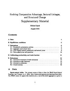
various stages respectively throughout the manufacturing process. FIG. 7 is a cross-sectional vieW through another embodi ment of a ?exible material according to the invention.
VELCRO(TM) to enable it to be a?ixed to itself or to another
article, say a garment. In one embodiment, the elements could comprise a series of spaced-apart strips. Such a material Would have different
FIG. 2 shoWs a schematic vieW of a protective arm band
formed from the type of material of FIG. 1. FIG. 3 is a plan vieW ofa cutter grid.
65
DETAILED DESCRIPTION OF THE INVENTION
Referring to FIG. 1, a ?exible material comprises a plural ity of cubes 1 of a resilient closed-cell polyethylene foam, of
US RE41,346 E 6
5 side approximately 12 mm and With corners of radius approximately 2.5 mm, joined With a hot melt adhesive to a
In a further variation, the sheet of resilient material is cut
into strips in a ?rst direction using a plurality of rolling
fabric substrate 2. The cubes 1 are evenly arranged, each
cutters. The sheet is cut in a second direction perpendicular to the ?rst to form cubes. The cutters are then moved side Ways to cut narroW strips of foam in both directions to space
cube being spaced from adjacent cubes by approximately 2 mm. The fabric 2 is a resiliently stretchable knitted fabric,
preferably one comprising polyester or elastane ?bers. A margin of fabric 2 is provided around the periphery of the cubes 1. Along the edges of the fabric at opposite ends respectively there are strips 3 of VELCROUM), only one of Which is shoWn. Referring to FIG. 2, a protective armband 4 is shoWn
the cubes apart, the narroW strips of foam being stripped aWay to leave the cubes. FIG. 7 shoWs another embodiment of ?exible material similar to that shoWn in FIG. 1, but With a layer of fabric 16
bonded to each of opposite sides of tho elements 17. This embodiment may be produced in a similar Way to that shoWn in FIG. 1 except that opposite sides of the foam layer are coated With adhesive and, after the foam cubes bonded to a ?rst layer of fabric have been removed from the cutter, a second layer of fabric is placed over the exposed surface of
being Worn on part of an arm 5. The armband 4 is formed
from a generally rectangular piece of material of the type shoWn in FIG. 1 but Which in this case comprises a fabric substrate 6 bonded to both sides thereof With a plurality of foam cubes 7 sandWiched therebetWeen. Margins are pro vided at opposite ends respectively of the substrate 6 and a
the elements are pressed With a heated platen to effect a
strip of VELCRO(TM) 8 is fastened on this margin to enable opposite ends of the material to be fastened in an overlaying
relationship to form a tube. By varying the degree of overlap of the ends, the tube can be closely ?tted around arms of different siZes. The provision of a substrate layer 6 on both sides of the cubes 7 prevents the latter from separating too much as the material is curved around to form a tube. Rather, the substrate 6 on the outside of the armband is forced to stretch and the edges of the cubes 7 at the inner side of the armband are compressed. The provision of a substrate layer on both sides of the material therefore enables the material to
20
25
continue to provide good protection, even When tightly 30
ing the material of FIG. 1. The cutter comprises blades
tus at various stages respectively throughout the manufac ture of the ?exible material shoWn in FIG. 1. Referring to these ?gures, one side ofa 12 mm thick layer of closed cell polyethylene foam 10 is coated With a hot melt adhesive 11. The foam 10 is then placed onto a cutter 12, of the type shoWn in FIG. 3, and pressed doWn With a press 13 so that the cutter 12 cuts through the foam 10 to form a plurality of
ety of applications including protective Wear and clothing. 35
Then, as shoWn in FIG. 6, the fabric can be lifted aWay from the cutter taking the foam cubes 10 With it. In an alternative method, ejectors are disposed in the cut
ments using a cutter Which is pressed into the sheet to 40
ments to stand proud of a surface of a jig provided to bonding a ?exible resiliently stretchable substrate to one
side of the separate elements by heating the substrate
45
either to activate an adhesive applied betWeen said one side of the separate elements and the substrate or to
50
Weld the separate elements to the substrate. 2. The method as claimed in claim 1 Wherein the sheet is cut into a plurality of separate elements using a cutter Which
acts as the jig after cutting through the resilient material to hold the elements in place While the substrate is applied
55
thereto. 3. The method as claimed in claim 2, Wherein the cutter is adapted so that said one side of each of the cut elements is made to stand proud of a surface of the cutter after cutting
through said sheet of resilient material. 4. The method as claimed in claim 3, Wherein any excess
behind in the cutters.
use in an equestrian jacket, then these pieces may be assembled into a specially constructed jig to hold them into place before application of the fabric substrate 14. As described above, the sheet of resilient foam from Which the
cut therethrough; making one side of the plurality of spaced separate ele hold the elements in place; and
ter grid to eject the elements, leaving any Waste material If the foam 10 is to be cut into large pieces, in particular large irregularly shaped pieces such as may be suitable for
I claim: 1. A method of manufacturing a ?exible material compris ing the steps of providing a sheet of a resilient material;
cutting the sheet into a plurality of spaced separate ele
separate cubes. The press is then removed, Whereupon oWing to its resilient nature, the foam Will tend to spring back slightly so that the exposed surface of each cube stands proud to lie above the surface of the cutter. Excess material from betWeen the elements is then removed. Next, as shoWn in FIG. 5, a layer of fabric is placed over the foam and cutter 12 and a heated platen 15 is brought into contact With the fabric 14. Heat is conducted through the fabric 14 to the foam and activates the adhesive, bonding the fabric 14 to the foam 10. In this arrangement, the cutter grid acts as a jig, holding the foam cubes in position Whilst the fabric substrate 14 is applied thereto.
Flexible materials according to the invention are more convenient to produce and more ?exible and versatile that
knoWn protective materials. They may also be used in a vari
de?ning a plurality of squares of 12 mm side With comers of radius 2.5 mm.
FIGS. 4 to 6 are vertical cross-sectional vieWs of appara
platen to bond the elements to the substrate, particularly When substrate is bonded to both sides of the elements, Which are thereby sandWiched therebetWeen. This facilitates passage of the material betWeen the rollers prior to activation of the adhesive.
?exed. FIG. 3 shoWs a plan vieW of a cutter used for manufactur
bond. In other variations to the above methods, the hot-melt adhesive may be applied to the surface the substrate rather or in addition to the sides of the ?exible material. Alternatively or in addition, a hot-melt ?lm can be interposed betWeen the elements and the substrate. Also, heated nip-rollers can be used in place of a heated
resilient material located betWeen the plurality of spaced 60
separate elements is retained in the cutter. 5. The method as claimed in claim 3, Wherein any excess
resilient material is removed from betWeen the plurality of
spaced separate elements prior to the elements being bonded 65
to the substrate. 6. The method as claimed in any of claim 1, Wherein the
elements are cut Will have hot-melt adhesive applied to one
plurality of spaced separate elements comprise a foam mate
or both surfaces prior to the cutting process.
rial.
US RE41,346 E 8
7 7. The method as claimed in claim 1, further comprising: bonding a second ?exible substrate to an opposite side of the plurality of spaced separate elements to said one side. 8. The method as claimed in claim 1, Wherein at least said one side of the sheet is coated With a hot-melt adhesive prior
18. The method according to claim 15 wherein the ele ments are distributed between the substrates at a density of
from about 4000 to about 6000 elements/m2. 19. The method according to claim 18 wherein the top and 5
to being cut into the plurality of spaced separate elements.
pressible material comprising: providing a first resiliently stretchable fabric substrate;
9. The method as claimed in claim 1, Wherein the side of
the substrate adjacent said one side of the plurality of spaced separate elements is coated With a hot-melt adhesive. 10. The method as claimed in claim 1, Wherein a sheet of hot-melt ?lm is interposed betWeen said one side of the plu rality of spaced separate elements and the substrate so as to
bottom surfaces have a polygonal shape. 20. A method ofmanufacturing a?exible resiliently com
10
cutting a sheet of resiliently compressible foam with a cutter to provide an array of a plurality of separate individual resiliently compressiblefoam elements in a spaced apart relationship, the cutter acting as a jig
provide said adhesive.
after cutting through the resiliently compressible foam
11. The method as claimed in claim 1, Wherein the sheet of resilient material is cut into strips in a ?rst direction using a plurality of rolling cutters and then cut in a second direc tion at an angle to the ?rst direction to form the plurality of
to hold the elements in place, the individual elements having a planar top surface and bottom surface in an
array of top surfaces and bottom surfaces; providing a second resiliently stretchable fabric sub
spaced separate elements. 12. The method as claimed in claim 11 Wherein the rolling
20
cutters are moved sideWays after each cut to cut narroW
strips of material in both directions to space the elements apart, the narroW strips of material being removed to leave
strates while the cutter holds the elements in place; and
the plurality of spaced separate elements spaced from one
adhesively bonding the top and bottom surfaces ofcom
another. 13. The method as claimed in claim 1 Wherein the sub strate is heated by a heated platen Which either activates the adhesive or melts the surface and thereby bonds the substrate
pressible elements to the first and second resiliently stretchable fabric substrates so that the elements will be held in a spaced apart relation with spaces between the elements, the fabric substrates not bonded to each
and the plurality of spaced separate elements together. 14. The method as claimed in claim 10, Wherein the sub
30
strate is heated by passing the substrate and the adjacent
2]. The method according to claim 20 wherein thefoam
rollers.
elements comprisefoam with oflayers offoam having di er
15. A method ofmanufacturing a?exible resiliently com
ent densities.
pressible material comprising: providing a first resiliently stretchable fabric substrate;
22. A method ofmanufacturing a?exible resiliently com
pressible material comprising: providing a first resiliently stretchable fabric substrate;
providing an array ofa plurality ofseparate individual resiliently compressible elements in a spaced relationship, the individual elements having a top sur
cutting a layer offoam with a cutter grid having cutting 40
bottom surfaces; strate;
apart relationship, the individual elevens being spaced 45
about 2 mmfrom each other, the array ofelements hav ing top and bottom surfaces;
bonding one ofthe surfaces ofthe array oftheplurality of
strates; and
bonding the top and bottom surfaces ofcompressible ele ments to the first and second resiliently stretchable fab
edges which go completely through the foam layer to provide an array ofa plurality of separate cut indi vidual resiliently compressible elements which have been cutfrom thefoam and after cutting are in a spaced
providing a second resiliently stretchable fabric sub
contacting the top surfaces and the bottom surfaces of the plurality of resiliently compressible elements with the first and second resiliently stretchable fabric sub
other in the spaces and to provide the ?exible resiliently
compressible material.
plurality of spaced separate elements betWeen heated nip
face and bottom surface in an array of top surfaces and
strate;
contacting the top surfaces and the bottom surfaces of the plurality ofresiliently compressible elements with one of the first and second resiliently stretchablefabric sub
50
separate cut individual resiliently compressible ele ments to the first resiliently stretchable fabric substrate
ric substrates so that the elements will be held in a
while the separate cut individual elements are held in
spaced apart relation with spaces between the elements, the bonding selected from the group consist
the spaced apart relationship with a jig to provide a
fabric element combination, the elements ofthefabric
ing ofadhesively bonding and welding, thefabric sub strates not bonded to each other in the spaces of about
2 mm and to provide the ?exible resiliently compress ible material, wherein a sheet ofresiliently compress ible material is cut into the plurality ofseparate indi vidual resiliently compressible elements using a cutter which acts as a jig after cutting through the resiliently compressible material to hold the elements in place while contacting one of the substrates to the elements. 16. The method as claimed in claim 15 wherein theplural
element combination held in spaced bonded relation 55
providing a second resiliently stretchable fabric sub strate;
bonding the second resiliently stretchable fabric substrate 60
17. The method according to claim 16 wherein thefoam
material comprises layers offoam having diferent densities.
to the elements ofthefabric element combination to the
elements on the side ofthe array opposite the?rstfab ric substrate so that the elements will be held in a
ity ofindividual resiliently compressible elements comprises afoam material.
ship;
65
spaced apart relation between the first and second resiliently stretchable fabric substrates with spaces between the elements, the fabric substrates not bonded to each other in the spaces and to provide the ?exible
resiliently compressible material.
US RE41,346 E 9 23. The method according to claim 22 wherein the ele
10 25. The method according to claim 22 wherein the ele
ments are distributed between the substrates at a density of
ments are distributed between the substrates at a density of
from about 250 to about 8000 elements/m2 between the sub
from about 4000 to about 8000 elements/m2 between the substrates.
strates.
24. The method according to claim 23 wherein the ele
ments are comprised of layers offoam having diferent den sities.
UNITED sTATEs PATENT AND TRADEMARK OFFICE
CERTIFICATE OF CORRECTION PATENT NO.
: RE 41,346 E
Page 1 of 1
APPLICATION NO. : 11/269919
DATED
: May 25, 2010
INVENTOR(S)
: David Stirling Taylor
It is certified that error appears in the above-identified patent and that said Letters Patent is hereby corrected as shown below:
Column 1, line 50, change “foram” to -- foam -
Column 1, line 66, change “for ,sports” to -- for sports Column 2, line 30, change “active” to -- activate Column 2, line 41, change “con?rm” to -- conform -
Column 3, line 45, change “for,,” to -- for Column 8, line 44, change “elevens” to -- elements -
Signed and Sealed this
Twenty-fourth Day of August, 2010
David J. Kappos Director of the United States Patent and Trademark Of?ce