www.sciencemag.org/cgi/content/full/science.1218461/DC1
Supporting Online Material for
Field-Effect Tunneling Transistor Based on Vertical Graphene Heterostructures L. Britnell, R. V. Gorbachev, R. Jalil, B. D. Belle, F. Schedin, A. Mishchenko, T. Georgiou, M. I. Katsnelson, L. Eaves, S. V. Morozov, N. M. R. Peres, J. Leist, A. K. Geim, K. S. Novoselov,* L. A. Ponomarenko
*To whom correspondence should be addressed. E-mail:
[email protected]
Published 2 February 2012 on Science Express DOI: 10.1126/science.1218461 This PDF file includes: Materials and Methods SOM Text Figs. S1 to S5 References (31–35)
Supplementary Online Material Field‐effect tunneling transistor based on vertical graphene heterostructures L. Britnell et al #1 Experimental structures Our devices contain two graphene Hall bars placed on top of each other with a thin layer of hBN in between. Figure S1 shows one of the studied devices. The turquoise area in Fig. S1A is a thick hBN crystal on top of an oxidized Si wafer (brown‐purple). The hBN layer served as a substrate to ensure the quality of the bottom graphene electrode. The actual graphene‐hBN‐graphene‐hBN sandwich is highly transparent and practically invisible on this image taken in an optical microscope (Fig. S1A). Nonetheless, one may discern a mesa structure in the central area between the Au leads. The multilayer Hall bar geometry is illustrated in Fig. S1B. This is an electron micrograph of the same device but before depositing Au contacts. The colored image of various layers was used at a design stage for the last round of electron‐beam lithography. The Au leads (deposited later) are shown in violet, and two graphene mesas in orange and green. The hBN crystal used as the tunnel barrier can be seen as a light grey patch of irregular shape. Its thickness was determined using atomic force microscopy, Raman microscopy and optical contrast (26).
Figure S1. One of our hBN‐graphene‐hBN‐graphene‐hBN devices. (A) Optical image of the final device. (B) Electron micrograph of the same device at the final design stage before evaporating Au leads. Two 10‐terminal Hall bars made from graphene are shown in green and orange. The spatial scale is given by the width of the Hall bar, which was 2 m for this device. Fabrication required 4 dry transfers and alignments of the graphene and hBN crystals, 4 nonconsecutive rounds of electron‐beam lithography, 3 rounds of plasma etching and two separate metal depositions.
1
#2 Penetration of electric field through the graphene electrode Consider the geometry shown in Fig. 1A of the main text. The external electric field between the Si and bottom graphene electrodes, which are separated by distance D, is Fg =Vg/D (dielectric constants for both SiO2 and hBN are similar and, for simplicity, we assume them both equal to ). The electric field Fb between GrB and GrT and the induced carrier densities in the graphene plates nT and nB are related by the equations (Fb –Fg) =4nBe ‐Fb =4nTe A bias voltage Vb between the two graphene electrodes is given by eVb = eFbd ‐ (nT) + (nB) where d is the hBN thickness and (n) are the chemical potentials in the corresponding graphene layers. For simplicity, we assume that graphene electrodes are chemically undoped and, therefore, nT = nB =0 in the absence of applied voltages. Taking into account the electron‐hole symmetry (‐n) =‐(n), we obtain the following equation
Fg 4e 2d eVb 0 nT nT nT 4e
(S1)
which allows us to determine nT induced by the field effect in GrT for a given Vg. For a conventional two‐ dimensional (2D) electron gas, n n and the first term in eq. (S1), which describes the classical capacitance of the tunnel barrier, is dominant for any realistic d, larger than interatomic distances. In graphene with its low DoS and Dirac‐like spectrum, n n and this leads to a qualitatively different behavior, which can be described in terms of quantum capacitance (27) (also note the discussion of doping of graphene through an hBN spacer in ref. 31). The above expressions were employed to find nT and nB as a function of bias Vb and gate voltage Vg and the results were then used to model the I‐V characteristics (see the theory curves in Fig. 3 of the main text). To illustrate the agreement between the experiment and theory at the intermediate stage of determining nT and nB, Figure S2 shows the same experimental data for carrier concentrations in the top and bottom graphene layer n(Vg) as in Fig. 2B,C and compares them with the behavior expected from solving eq. (S1).
2
Figure S2. Nonlinear dependence of charge carrier concentrations in the two graphene electrodes as a function of gate voltage. The symbols are experimental data (red symbols for the bottom graphene layer; blue for the top). The solid curves in the corresponding colors are our modeling. No fitting parameters are used. #3 Modeling of our device operation I‐V curves for a tunnel junction are generally described by (23) I V dEDoS B E DoST E eV T ( E )[ f ( E eV ) f ( E )]
(S2)
where f(E) is the Fermi distribution function. At low temperatures the difference of the Fermi functions restricts the relevant energy E integral to E eV where μ is the chemical potential and, to be specific, we consider the case eV > 0. The above formula assumes that there is no in‐plane momentum conservation, which is most likely to be the case of realistic graphene‐hBN interfaces. There are several possible mechanisms for elastic scattering at the interface and, in particular, unavoidable fluctuations of the mass term due to the lattice mismatch (32). Note that elastic tunneling is forbidden between two 2D systems if in‐plane momentum is conserved. If the tunneling conductance per channel is much smaller than the conductivity quantum e2/h (as in our case) the transmission probability T is exponentially small and depends strongly on the energy E of tunneling electrons,
T E AE exp W E
3
(S3)
where A is a smooth function that depends on details of the wave‐function matching at the interface. In our modeling, we assume A=const. Let us now discuss some functional forms of W(E). For the case of an isotropic barrier, we need to solve
the dispersion equation E n k x , k y , k z for each band of the barrier material, where E is the energy of
electrons tunneling in the z direction. No real solution for kz is possible inside the energy gap, and the minimal Imkz Im k z for a given E and arbitrary kx and ky, which dominates the tunneling probability, is given by W E 2d Im k z
For the case of parabolic bands, Im k z
2 m where Δ is the barrier height (in our case, the distance
to the valence band) and m is the effective mass (22,23,33). In the case of layered crystals, their band structure can be described in the simplest approximation as
k x , k y , k z k z 1 k x , k y
(S4)
where (kz) =2tcos(kzl); t describes the interlayer coupling and l is the interlayer distance (for the case of hBN, l 3.4Å). By solving the corresponding tunneling equation, we find kz within the gap to be 2 E 1 i E 1 1 k z ln l 2t 2t
The top of the valence band corresponds to Emax max 1 (k x , k y ) 2t (to be specific, we choose t >0), and the optimal value for the tunneling wavevector is then 1 1 Im k z ln l 2t
2 1 1 2t
i
(S5)
where E Emax . If 2t , this expression can be simplified as k z ln and yields the tunneling l t probability T (t/Δ)2n where n =d/l is the number of atomic layers in the tunnel barrier. In the opposite limit 2t , we obtain k z
2 i 2m* where m* is the effective mass in the i l t 2tl 2
tunneling direction. This shows that the standard isotropic model is applicable to layered crystals, provided the tunneling occurs not too far from the band‐gap edge.
4
Eq. (S4) is a simplified version of the real band structure of hBN, which depends on stacking order. hBN crystals usually have AA’ stacking (34). In the next approximation that allows an analytical solution by neglecting the mixing of π and σ bands (29,30), we obtain the following dispersion relation [S4]
2 kx , k y , kz
E g2 4
2 k z 12 k x , k y 2k z 1 k x , k y
(S6)
where Eg is the energy difference between boron and nitrogen sites (34). In this case, we find 2 1 1 Im k z ln 2 l 2t t
where E 2
E g2 4
(S7)
1 k x , k y . Eq. (S7) differs from (S5) by replacement E E 2 E g2 / 4 , which
indicates the general validity of equation Imkz ln() for describing vertical tunneling through strongly layered materials. (S5) and (S7) fit our experimental data equally well. It is worth noting that the tunneling exponent through layered crystals depends on E only weakly (logarithmically) in comparison with isotopic crystals that exhibit the standard square‐root energy dependence. For small changes in , this difference is unimportant (see below). Finally, in the case of a strong electric field such that it changes the rectangular shape of the tunnel barrier (Fig. 1D) the above expressions for W can be generalized within the WKB approximation (33) as d
W 2 dx Im k z x .
0
#4 Layered versus isotropic barrier In the main text, we have chosen for the sake of brevity to ignore the fact that our tunnel barriers are made from a strongly layered material. This simplification allowed us to refer to the standard tunneling theory. However, the assumption can be justified further by the fact that, for our device parameters, we have found no difference between the I‐V characteristics calculated for the layered and isotropic materials and, therefore, we cannot distinguish between the two cases. To illustrate the indifference to the layered structure of our tunnel barrier, Figure S3 shows experimental I‐V curves for two devices and compares them with the behavior expected for layered and isotropic cases. No major difference can be
5
seen, except at low bias in Fig. S3A. The exact shape of experimental curves at low bias varies from sample to sample (cf. Fig. S3A & B) and, hence, we do not discuss the difference.
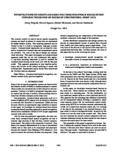
Figure S3. Tunneling I‐V characteristics for two different 4‐hBN‐layer devices at zero gate voltage and their comparison with theory. (A) The red solid curve is the experimental data from Fig. 3. The two dashed curves are our modeling for an isotropic barrier ( and m as in the main text) and for a layered barrier of the same height and t =0.6eV, by using formulae from the above section. Note that t 0.6eV corresponds to m =0.5m0. (B) Nominally similar device (for clarity, the experimental data are shown by symbols). The curves are again the layered and isotropic versions of the tunneling theory. The fitting parameter is the constant A in eq. (S3), which determines the absolute value of I. The close agreement between functional forms of the theoretical curves validates the use of the conventional tunneling formulae in the main text. #5 Additional examples of our device operation We have studied 6 multiterminal devices such as shown in Fig. S1 and >10 simpler tunneling FETs with only one or two Ohmic contacts attached to each graphene electrode. The latter type does not provide much information about the properties of the graphene electrodes but even one contact is sufficient to study their tunneling I‐V characteristics. The devices with the same hBN thickness have exhibited qualitatively similar behavior, as discussed in the main text. To illustrate the degree of reproducibility for different samples, Figure S4 plots the behavior observed in another device with the tunnel barrier consisting of 4 hBN layers. One can see that the nonlinear I‐V characteristics are qualitatively similar to those presented in the main text, and their response to gate voltage is also similar.
6
Figure S4. Another hBN‐graphene‐hBN‐graphene‐hBN field‐effect device. (A) Tunneling I‐Vs and their response to gate voltage (in 5V steps, cf. Fig. 3 of the main text). The inset compares the experimental I‐ V at zero gate voltage (red curve) with theory (dark) which takes into account the linear DoS in the two graphene layers and assumes no momentum conservation.Temperature: 300 K. (B) Changes in low‐bias tunneling (symbols) and the theory fit for 4 hBN layers (solid curve). The main difference with respect to the device in the main text is a weak response at low gate voltages, which is probably due to stronger disorder and chemical doping that smears the gate influence. The electron‐hole asymmetry again implies the hole tunneling as discussed in the main text. The only consistent difference that we noticed for a number of devices with 4 or more atomic layers of hBN was the absolute value of T which could vary by a factor of 100 for nominally the same d. Although this can be attributed to possible errors in determining the number of layers in thicker hBN (26), more careful analysis of the devices’ response to bias and gate voltages reveals that the reason for these variations is more likely to be inhomogeneous thickness of hBN. We believe that in some devices one or two layers can be missing locally (in submicron scale patches) so that the tunnel current then concentrates within these thinner areas. Graphite is known to cleave leaving occasional stripes of smaller thickness for few‐layer graphene crystals and, whereas it is possible to see missing graphene patches in an optical microscope, hBN does not allow the required resolution (26).
7
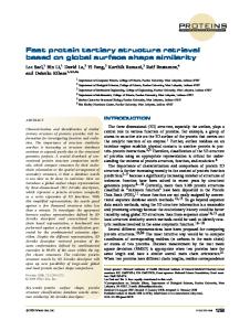
#6 Vertical transistors using few‐layer MoS2 as a barrier One of the possible routes to increase the ON‐OFF ratio is to use materials with smaller . In this way it would be viable to use thicker barriers but shift EF closer to the barrier edge, which should allow exponential dependence of the tunnel current on gate voltage. One of the candidate materials is MoS2. It is a layered semiconductor, which can be cleaved down to a monolayer (24). It has an indirect band gap of 1.3eV (35), significantly lower than that in hBN. We have exploited MoS2 to prepare graphene‐ MoS2 devices by using the same procedures as described in the main text and in #1 of SOM. I‐V characteristics for a transistor with a 6‐layer MoS2 barrier are presented in Figure S5A. Measurements of its conductivity at a fixed small bias as a function of gate voltage are plotted in Fig. S5B. The dependence is clearly exponential and in this device an ON‐OFF ratio of 10,000 has been achieved. Further work is needed to improve the observed ratios further and to verify whether the mechanism responsible for vertical transport through MoS2 is indeed tunneling.
Figure S5. I‐V characteristics of a graphene MoS2 device. Thickness of MoS2 is 6 layers. (A) ‐ Different curves correspond to various gate voltages applied. Black: ‐40V; red: ‐20V; blue: 0V; purple: +20; green: +40V. (B) ‐ Conductivity measured at a bias voltage of 0.2V as a function of gate voltage. The ON/OFF ratio of >7103 is observed even for the relatively limited range of gate voltages. Supplementary References 31.
M. Bokdam et al., Electrostatic doping of graphene through ultrathin hexagonal boron nitride
films. Nano Lett. 11, 4631‐4635 (2011).
8
References and Notes 1. P. Avouris, Z. H. Chen, V. Perebeinos, Carbon-based electronics. Nat. Nanotechnol. 2, 605 (2007). doi:10.1038/nnano.2007.300 Medline 2. A. K. Geim, Graphene: Status and prospects. Science 324, 1530 (2009). doi:10.1126/science.1158877 Medline 3. F. Schweirz, Graphene transistors. Nat. Nanotechnol. 5, 487 (2010). doi:10.1038/nnano.2010.89 4. Y. Wu et al., High-frequency, scaled graphene transistors on diamond-like carbon. Nature 472, 74 (2011). doi:10.1038/nature09979 Medline 5. L. Liao et al., High-speed graphene transistors with a self-aligned nanowire gate. Nature 467, 305 (2010). doi:10.1038/nature09405 Medline 6. S. J. Han et al., High-frequency graphene voltage amplifier. Nano Lett. 11, 3690 (2011). doi:10.1021/nl2016637 Medline 7. Y. M. Lin et al., Wafer-scale graphene integrated circuit. Science 332, 1294 (2011). doi:10.1126/science.1204428 Medline 8. E. V. Castro et al., Biased bilayer graphene: Semiconductor with a gap tunable by the electric field effect. Phys. Rev. Lett. 99, 216802 (2007). doi:10.1103/PhysRevLett.99.216802 Medline 9. J. B. Oostinga, H. B. Heersche, X. Liu, A. F. Morpurgo, L. M. K. Vandersypen, Gate-induced insulating state in bilayer graphene devices. Nat. Mater. 7, 151 (2008). doi:10.1038/nmat2082 Medline 10. M. Y. Han, B. Ozyilmaz, Y. B. Zhang, P. Kim, Energy band-gap engineering of graphene nanoribbons. Phys. Rev. Lett. 98, 206805 (2007). doi:10.1103/PhysRevLett.98.206805 Medline 11. C. Stampfer et al., Transport in graphene nanostructures. Front. Phys. 6, 271 (2011). 12. D. C. Elias et al., Control of graphene’s properties by reversible hydrogenation: Evidence for graphane. Science 323, 610 (2009). doi:10.1126/science.1167130 Medline 13. S. Luryi, Quantum capacitance devices. Appl. Phys. Lett. 52, 501 (1988). doi:10.1063/1.99649 14. M. Heiblum, M. V. Fischetti, Ballistic hot-electron transistors. IBM J. Res. Develop. 34, 530 (1990). doi:10.1147/rd.344.0530 15. J. A. Simmons et al., Planar quantum transistor based on 2D–2D tunneling in double quantum well heterostructures. J. Appl. Phys. 84, 5626 (1998). doi:10.1063/1.368610 16. A. Zaslavsky et al., Ultrathin silicon-on-insulator vertical tunneling transistor. Appl. Phys. Lett. 83, 1653 (2003). doi:10.1063/1.1600832 17. A. Sciambi et al., Vertical field-effect transistor based on wave-function extension. Phys. Rev. B 84, 085301 (2011). doi:10.1103/PhysRevB.84.085301 18. Materials and methods are available as supporting material on Science Online. 1
19. C. R. Dean et al., Boron nitride substrates for high-quality graphene electronics. Nat. Nanotechnol. 5, 722 (2010). doi:10.1038/nnano.2010.172 Medline 20. A. S. Mayorov et al., Micrometer-scale ballistic transport in encapsulated graphene at room temperature. Nano Lett. 11, 2396 (2011). doi:10.1021/nl200758b Medline 21. K. S. Novoselov et al., Two-dimensional atomic crystals. Proc. Natl. Acad. Sci. U.S.A. 102, 10451 (2005). doi:10.1073/pnas.0502848102 Medline 22. L. A. Ponomarenko et al., Tunable metal–insulator transition in double-layer graphene heterostructures. Nat. Phys. 7, 958 (2011). doi:10.1038/nphys2114 23. R. V. Gorbachev et al., Hunting for monolayer boron nitride: Optical and Raman signatures. Small 7, 465 (2011). doi:10.1002/smll.201001628 Medline 24. A. H. Castro Neto, F. Guinea, N. M. R. Peres, K. S. Novoselov, A. K. Geim, The electronic properties of graphene. Rev. Mod. Phys. 81, 109 (2009). doi:10.1103/RevModPhys.81.109 25. J. G. Simmons, Generalized formula for the electric tunnel effect between similar electrodes separated by a thin insulating film. J. Appl. Phys. 34, 1793 (1963). doi:10.1063/1.1702682 26. E. L. Wolf, Principles of electron tunneling spectroscopy. Oxford University Press (1985). 27. L. A. Ponomarenko et al., Density of states and zero Landau Level probed through capacitance of graphene. Phys. Rev. Lett. 105, 136801 (2010). doi:10.1103/PhysRevLett.105.136801 Medline 28. J. M. Xue et al., Scanning tunnelling microscopy and spectroscopy of ultra-flat graphene on hexagonal boron nitride. Nat. Mater. 10, 282 (2011). doi:10.1038/nmat2968 Medline 29. N. Kharche, S. K. Nayak, Quasiparticle band gap engineering of graphene and graphone on hexagonal boron nitride substrate. Nano Lett. 11, 5274 (2011). doi:10.1021/nl202725w Medline 30. Y. N. Xu, W. Y. Ching, Calculation of ground-state and optical properties of boron nitrides in the hexagonal, cubic, and wurtzite structures. Phys. Rev. B 44, 7787 (1991). doi:10.1103/PhysRevB.44.7787 Medline 31. M. Bokdam, P. A. Khomyakov, G. Brocks, Z. Zhong, P. J. Kelly, Electrostatic doping of graphene through ultrathin hexagonal boron nitride films. Nano Lett. 11, 4631 (2011). doi:10.1021/nl202131q Medline 32. B. Sachs, T. O. Wehling, M. I. Katsnelson, A. I. Lichtenstein, Adhesion and electronic structure of graphene on hexagonal boron nitride substrates. Phys. Rev. B 84, 195414 (2011). doi:10.1103/PhysRevB.84.195414 33. L. D. Landau, E. M. Lifshitz, Quantum Mechanics. Oxford: Pergamon (1977). 34. R. M. Ribeiro, N. M. R. Peres, Stability of boron nitride bilayers: Ground-state energies, interlayer distances, and tight-binding description. Phys. Rev. B 83, 235312 (2011). doi:10.1103/PhysRevB.83.235312 35. Gmelin, Gmelin handbook of inorganic and organometallic chemistry (SpringerVerlag, Berlin, 1995). 2