APPLIED PHYSICS LETTERS 97, 191905 共2010兲
Experimental demonstration of multiwire endoscopes capable of manipulating near-fields with subwavelength resolution Pavel A. Belov,1,2 George K. Palikaras,1 Yan Zhao,3,a兲 Atiqur Rahman,1 Constantin R. Simovski,2,4 Yang Hao,1 and Clive Parini1 1
School of Electronic Engineering and Computer Science, Queen Mary University of London, Mile End Road, London E1 4NS, United Kingdom 2 St. Petersburg State University of Information Technologies, Mechanics and Optics, Sablinskaya Street 14, 197101 Saint Petersburg, Russia 3 International School of Engineering, Faculty of Engineering, Chulalongkorn University, Phayathai Road, Pathumwan, Bangkok 10330, Thailand 4 Department of Radio Science and Engineering, School of Science and Technology, Aalto University, P.O. Box 13000, FI-00076 Aalto, Finland
共Received 6 October 2010; accepted 22 October 2010; published online 9 November 2010兲 Endoscopes formed by arrays of metallic wires can transmit, magnify, and demagnify near-field distributions with subwavelength resolution. Our experiments demonstrate that despite their small apertures, the parallel multiwire endoscopes can be used to transmit near-field distributions with a resolution of five thousandths of a wavelength to a distance of a half-wavelength in the microwave frequency range, and tapered multiwire endoscopes with flat input and output interfaces provide threefold image magnification and demagnification. © 2010 American Institute of Physics. 关doi:10.1063/1.3516161兴
a兲
Author to whom correspondence should be addressed. Electronic mail:
[email protected].
0003-6951/2010/97共19兲/191905/3/$30.00
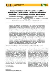
prising TM-polarized incident waves with any transverse components of the wave vector. The canalization principle requires the thickness of the wire medium to be n / 2, n = 1 , 2 , . . ., to satisfy the Fabry–Pérot resonant condition. In this work, an endoscope device formed by an array of 21⫻ 21 parallel brass wires with an equal length of 1 m and a radius of 1 mm is fabricated. A crown-shaped loop source printed on a 2 mm thick Duroid substrate with r = 2.33 is used as the near-field source. The detailed dimensions of the source can be found in Fig. 1共a兲. An automatic mechanical near-field scanning device is used in the experiment. The scanned area is 180 ⫻ 240 mm2 at both the source and image planes 关see Fig. Image plane
10
90
90
Source plane
165
158
150
10
0
100
15
78
(a)
(b)
Coaxial Feed
unit: mm Image plane
Source plane 9
9
6
6
3
3
y (cm)
y (cm)
Conventional dielectric lenses suffer from two major drawbacks: their resolution is limited to a half-wavelength 共 / 2兲 of the electromagnetic radiation and their transverse dimensions are required to be significantly larger than the wavelength in order to avoid aberrations. However, both limitations can be overcome by using devices made of materials with extreme anisotropy.1–3 Electromagnetic waves in these media do not experience cutoff and travel strictly along the axis of anisotropy without any diffraction effects. Such waveguiding property allows one to construct endoscope devices with thickness up to several wavelengths for subwavelength imaging applications. Structures with extreme optical anisotropy in microwave, terahertz,4 and infrared5–7 frequencies can be constructed using arrays of metallic rods. It has been demonstrated in literature that endoscopes formed by arrays of parallel metallic rods are capable of transferring images with subwavelength resolutions.5,6,8–11 The principle of operation is based on the transformation of the complete spectrum of spatial harmonics generated by the source, including evanescent waves, into propagating eigenmodes of the metallic array. Previous experimental works have demonstrated the transmission of images with / 15 resolution over a short distance of / 2 and a long distance of 3.8–10 Applications of such endoscopes range from magnetic resonance imaging 共MRI兲,12,13 to biomedical imaging,14 to near-field microscopy. In this letter, we report on the experimental results of image transmission using an endoscope formed by an array of parallel metallic wires, followed by the results of image magnification and demagnification using an endoscope formed by an array of tapered metallic wires. Arrays of parallel wires operate in the so-called “canalization” principle;1 therefore, they are capable of transmitting field patterns com-
0
-3
-6
-6
(c) -9
-6
-3
0
z (cm)
3
6
9
12
0.5
0
-3
-9 -12
1
0
(d)
-9 -12
-9
-6
-3
0
z (cm)
3
6
9
12
FIG. 1. 共Color online兲 共a兲 A crown-shaped near-field source and 共b兲 an endoscope formed by a parallel array of brass wires used in the experiment at a frequency of 150 MHz. Distributions of electric field amplitude in 共c兲 source and 共d兲 image planes.
97, 191905-1
© 2010 American Institute of Physics
Author complimentary copy. Redistribution subject to AIP license or copyright, see http://apl.aip.org/apl/copyright.jsp
191905-2
Appl. Phys. Lett. 97, 191905 共2010兲
Belov et al.
TABLE I. Recorded parameters from experiments of subwavelength image transmission through an array of parallel wires.
Source plane
150 300 450 600 750 900 1050
/ 200 / 100 / 70 / 50 / 40 / 35 / 30
共 / 10兲2 共 / 5兲2 共 / 3.5兲2 共 / 2.5兲2 共 / 2兲2 共 / 1.75兲2 共 / 1.5兲2
0.5 1.5 2 2.5 3 3.5
100
105
Thickness
52
Aperture
(a)
45
5
15
Resolution
90
Frequency 共MHz兲
55
15
Image plane
0
100 Coaxial Feed
(b)
unit: mm Image plane 16
1
12
Source plane 6
8
9
0.5
4 4.5
2 0
0
-2
-4
4
y (cm)
y (cm)
1共b兲兴. The measured near-field distributions at a frequency of 150 MHz are shown in Figs. 1共c兲 and 1共d兲, respectively. It is clearly illustrated that a field distribution with a resolution of approximately / 200 is resolved at the image plane, while the aperture size and length of the device are 共 / 10兲2 and / 2, respectively. Similar measurements have been performed using the same device, and various parameters in the experiment are listed in Table I. The above results demonstrate the advantage of the proposed structure over negative-index material 共NIM兲 based endoscope devices: extremely high resolutions can be obtained using an array of parallel metallic wires with a large length and a small aperture size. So far, only images with a resolution of / 8 using a NIM lens with / 3 thickness have been reported.15 Furthermore, higher resolution and larger thicknesses of NIM lenses cannot be achieved due to the lossy nature of the material.16 Recently, there is a growing interest in the development of structures that are capable of magnifying subwavelength field distributions in the visible frequency range.17–20 These structures allow source details to be transferred to a certain distance, while maintaining the same patterns with a linearly magnified or enlarged scale. The capability of tapered arrays of wires to transmit, magnify, and demagnify images with subwavelength details has been reported in literature.6,10,14,21 However, the previously proposed device has spherical input and output interfaces,21 which is unsuited for many near-field imaging applications. Here, we report on the experimental results using a tapered array of wires with planar interfaces. Hence, phase distortions are introduced by the unequal length of wires in such a tapered array—the difference in physical length between the longest wires at four corners and the shortest wire at the center is approximately 10.05 mm. At the lowest operating frequency of 150 MHz where the length of the longest wires is equal to a half-wavelength 共 / 2兲, the maximum phase distortion can be estimated as k⌬lmax = 共2 / 兲⌬lmax = 0.032 rad. Previous studies demonstrate that the operating bandwidth of parallel endoscopes highly depends on the complexity of source distributions and is at least 5% for an arbitrary type of source with image resolution above / 15.9 The phase distortion introduced by tapering of wires reduces the bandwidth of operation considerably to around 3%, estimated from our experimental results. The bandwidth issue of magnifying and demagnifying endoscopes will be studied further and reported in a subsequent publication. It suffices to state that phase distortions can be eliminated using a dielectric phase compensator to adjust the electrical lengths of wires.22
0 0
-4
(c)
-6 -6 -4 -2
0
2
z (cm)
4
6
-8 -12
(d)
-16 -16
-12
-8
-4
0
z (cm)
4
8
12
16
FIG. 2. 共Color online兲 共a兲 A crown-shaped near-field source and 共b兲 an endoscope formed by a tapered array of brass wires used in the magnification experiment at 1047 MHz. Distributions of electric field amplitude in 共c兲 source and 共d兲 image planes.
The fabricated tapered array consists of 21⫻ 21 brass wires with their radius equal to 1 mm. The dimensions of the tapered array are shown in Fig. 2共b兲. A small crown-shaped loop source similar to the one used in the previous experiment is designed and fabricated. Detailed dimensions of the source can be found in Fig. 2共a兲. The same experimental setup as in the previous case is used and a series of measurements at frequencies around 1050 MHz is performed 共the thickness of the tapered array is approximately 3.5兲. The scanned areas are 120⫻ 120 and 320⫻ 320 mm2 in the source and image planes, respectively. The optimum result is obtained at 1047 MHz and shown in Figs. 2共c兲 and 2共d兲. The slight frequency deviation from the theoretical Fabry–Pérot resonance is caused by the gradually enlarged spacing between wires and the influence of slight manufacturing errors. Despite the frequency shift, the field distribution is satisfactorily reproduced at the image plane, with magnified characteristic dimensions by a factor of 3. As indicated by the scales of color bars in Figs. 2共c兲 and 2共d兲, the amplitude of the electric field in the image plane is approximately nine times lower than the source plane, which is caused by the ninefold increase in the distribution area. It is important to note that when the Fabry–Pérot resonant condition is met, it is not required to maintain a uniform transmission line characteristic impedance along the device23 共e.g., by altering the radius of wires6兲, which eases practical implementations of the device significantly. The magnification of images with subwavelength resolutions allows one to enlarge source details smaller than the wavelength up to the scale that can be detected using conventional diffraction-limited imaging systems. Moreover, the inverse operation is also possible: the tapered arrays are capable of demagnifying electromagnetic field distributions, through which, one may be able to obtain highly confined subwavelength distributions of arbitrary shapes required by a
Author complimentary copy. Redistribution subject to AIP license or copyright, see http://apl.aip.org/apl/copyright.jsp
191905-3
Appl. Phys. Lett. 97, 191905 共2010兲
Belov et al.
14
5
150
Source plane
5
(a)
1000
Image plane
50
140
290
250
240
15
(b)
Coaxial Feed
unit: mm
Source plane 16
1
12
Image plane 8
6 0.5
y (cm)
y (cm)
4 0
9
4 4.5
2 0
-4
1
(d)
-6 -6 -4 -2
-8
0
2
z (cm)
-12
4
6
(c)
-16 -16
-12
-8
-4
0
z (cm)
4
8
12
Pavel A. Belov acknowledges the financial support by EPSRC-GB through Advanced Research Fellowship 共Grant No. EP/E053025/1兲. Constantin R. Simovski and Pavel A. Belov thank the Ministry of Education and Science of Russian Federation for the financial support through Federal Targeted Programme “Scientific and Scientific-Pedagogical Personnel of the Innovative Russia in 2009-2013” events 1.2.1 and 1.2.2, respectively.
0
-2
0
-4
sides, the proposed device can be utilized in the opposite way to achieve image demagnification: electrically large source distributions can be “concentrated” to a confined area. Such near-field devices may find their applications in nearfield microscopy and medical imaging, ranging from MRI operating at low microwave frequencies to terahertz and infrared imaging.
16
FIG. 3. 共Color online兲 共a兲 A crown-shaped near-field source and 共b兲 an endoscope formed by a tapered array of brass wires used in the demagnification experiment at 455 MHz. Distributions of electric field amplitude in 共c兲 source and 共d兲 image planes.
particular application. In order to demonstrate the demagnification capability of the tapered array of wires, we interchange the source and image planes of the device, as illustrated in Fig. 3共b兲. A large crown-shaped loop source is designed and used in the demagnification experiment. The source is placed in front of the larger interface of the tapered array and nearfield scanning is performed at several frequencies around 450 MHz. The scanned results at 455 MHz are chosen and presented in Figs. 3共c兲 and 3共d兲. It is clearly shown that the distribution in the image plane reproduces the entire source details and has three times smaller dimensions. In conclusion, we have experimentally demonstrated the possibility of using dense arrays of metallic wires to transfer, magnify, and demagnify images with deep subwavelength resolution to significant distances at microwave frequencies. In particular, the transmission of an image with a resolution of / 200 to an electrical distance of / 2 is shown. A threefold image magnification with subwavelength resolution is demonstrated using a tapered array of metallic wires. Be-
P. A. Belov, C. R. Simovski, and P. Ikonen, Phys. Rev. B 71, 193105 共2005兲. 2 Y. Zhao, P. A. Belov, and Y. Hao, Opt. Express 14, 5154 共2006兲. 3 P. A. Belov, Y. Zhao, Y. Hao, and C. Parini, Opt. Lett. 34, 527 共2009兲. 4 M. Silveirinha, P. A. Belov, and C. R. Simovski, Opt. Lett. 33, 1726 共2008兲. 5 M. Silveirinha, P. A. Belov, and C. R. Simovski, Phys. Rev. B 75, 035108 共2007兲. 6 G. Shvets, S. Trendafilov, J. B. Pendry, and A. Sarychev, Phys. Rev. Lett. 99, 053903 共2007兲. 7 B. D. F. Casse, W. T. Lu, Y. J. Huang, E. Gultepe, L. Menon, and S. Sridhar, Appl. Phys. Lett. 96, 023114 共2010兲. 8 P. A. Belov, Y. Hao, and S. Sudhakaran, Phys. Rev. B 73, 033108 共2006兲. 9 P. A. Belov, Y. Zhao, S. Sudhakaran, A. Alomainy, and Y. Hao, Appl. Phys. Lett. 89, 262109 共2006兲. 10 P. A. Belov, Y. Zhao, S. Tse, P. Ikonen, M. G. Silveirinha, C. R. Simovski, S. Tretyakov, Y. Hao, and C. G. Parini, Phys. Rev. B 77, 193108 共2008兲. 11 A. Ono, J.-i. Kato, and S. Kawata, Phys. Rev. Lett. 95, 267407 共2005兲. 12 X. Radu, A. Lapeyronnie, and C. Craeye, Electromagnetics 28, 531 共2008兲. 13 X. Radu, D. Garray, and C. Craeye, Metamaterials 3, 90 共2009兲. 14 S. Kawata, A. Ono, and P. Verma, Nat. Photonics 2, 438 共2008兲. 15 K. Aydin, I. Bulu, and E. Ozbay, Appl. Phys. Lett. 90, 254102 共2007兲. 16 V. A. Podolskiy and E. E. Narimanov, Opt. Lett. 30, 75 共2005兲. 17 A. Salandrino and N. Engheta, Phys. Rev. B 74, 075103 共2006兲. 18 Z. Jacob, L. V. Alekseyev, and E. Narimanov, Opt. Express 14, 8247 共2006兲. 19 Z. Liu, H. Lee, Y. Xiong, C. Sun, and X. Zhang, Science 315, 1686 共2007兲. 20 I. I. Smolyaninov, Y.-J. Hung, and C. C. Davis, Science 315, 1699 共2007兲. 21 P. Ikonen, P. A. Belov, C. R. Simovski, Y. Hao, and S. Tretyakov, Appl. Phys. Lett. 91, 104102 共2007兲. 22 Y. Zhao, G. Palikaras, P. A. Belov, R. F. Dubrovka, C. R. Simovski, Y. Hao, and C. G. Parini, New J. Phys. 12, 103045 共2010兲. 23 A. Rahman, P. A. Belov, M. G. Silveirinha, C. R. Simovski, Y. Hao, and C. G. Parini, Appl. Phys. Lett. 94, 031104 共2009兲.
Author complimentary copy. Redistribution subject to AIP license or copyright, see http://apl.aip.org/apl/copyright.jsp