USOORE35924E
United States Patent [191 Winkler
Patent Number: Re. 35,924 [45] Reissued Date of Patent: Oct. 13, 1998 [11] E
Primary Examiner-Brian Casler
[54] ELECTRODE-CARRYING CATHETER AND METHOD OF MAKING SAME
Attorney, Agent, or Firm-Amster. Rothstein & Ebenstein
[75] Inventor: Josef Winkler. Reading_ Pa.
[57]
[73] Assignee: Arrow International Investment
An electrode-carrying catheter has elongate. ?exible tubing
Corp.. Reading. Pa. [21] Appl. No.: 764,729 [22] Filed:
Dec. 6, 1996 Related US. Patent Documents
Reissue of:
[64] Patent No.: Issued:
[51] [52] [58]
de?ning a proximal end. a distal end. and an electrically insulative outer tubular layer intermediate the ends. the tubing including a ?exible electrically conductive core of wire and a ?exible non-conductive core-covering layer of plastic about the core. At least one electrically conductive ring electrode is crirnped on and ?ush with the outer tubular surface. In order to conduct electrical signals between the proximal end and each of the ring electrodes. 21
5,417,208 May 23, 1995
ductive wires are helically wound around and at least
Appl. No.:
135,152
partially into the core-covering layer. The wound wires
Filed:
Oct. 12, 1993
de?ne a removed section beneath a segment of each of the ring electrodes to enable electrical contact between a respec tive one of the wound wires and a respective one of the ring electrodes An electrically conductive ?exible ?at ribbon is
longitudinally-spaced plurality of ?exible electrically con
Int. Cl.6 ...................................................... .. A61B 5/04 US. Cl. ............................................. .. 600/373; 607/98 Field of Search ............................. .. 128/642; 607/98.
607/99. 115. 116. 122; 604/280; 600/373 [56]
disposed intermediate each of the ring electrodes and the
tubing. each ribbon being electrically and physically joined
References Cited
to a respective one of the wound wires and wrapped about the outer tubular surface. each of the ring electrodes being
U.S. PATENT DOCUMENTS
crimped onto a respective one of the ribbons and the outer tubular surface.
3,804,098
4/1974 Friedman
4,280,511 4,957,110
7/1981 O’Neill .. 600/373 9/1990 Vogel et a]. .......................... .. 600/373
........... .. 600/373
10\ 14
ABSTRACT
30 Claims, 4 Drawing Sheets
US. Patent
Re. 35,924
US. Patent
Oct.13, 1998
Sheet 2 0f 4
Re. 35,924
US. Patent
Oct.13, 1998
Sheet 3 of 4
Re. 35,924
US. Patent
Oct. 13,1998
Sheet 4 0f 4
Re. 35,924
QNOW’A'
WN-n
Re. 35,924 1
2
ELECTRODE-CARRYING CATHETER AND METHOD OF MAKING SAME
human body over a guidewire since the diminished ?exibil ity may limit the ability of the catheter to conform to the
Matter enclosed in heavy brackets [ ] appears in the original patent but forms no part of this reissue speci? cation; matter printed in italics indicates the additions made by reissue.
are in favor because of the high level of reliability of the electrical connections therein. The conventional processes for forming ring or metal
travel path de?ned by the guidewire. leading to blood vessel trauma. Nonetheless. such catheters carrying ring electrodes
band electrodes ?ush with the outer surface of a catheter are
BACKGROUND OF THE INVENTION
arduous. time-consuming and/or require further processing.
The present invention relates to electrode-carrying catheters. and more particularly to an inexpensive and reliable electrode-carrying catheter and a method of malcing
For example. in one process metal bands and sleeves ther ebetween are slipped over the tubing outer surface with the
sleeves maintaining the appropriate spacing between adja
the same.
Electrode-carrying catheters as well know in the medical art and ?nd diagnostic and therapeutic utility in a wide
15
variety of di?’erent applications. For example. mapping
cent electrodes; this requires the use of additional pieces (namely. the sleeves) and an arduous assembly process. Another process requires the tubing to be stretched to lower the outer diameter thereof. metal bands placed over the
stretched tubing and disposed in appropriate spatial
catheters are used diagnostically to produce a wave function of the heart’s electrical impulses so that a doctor can
relationship. and the tubing then heated and released. The metal bands sink into the heat-softened tubing outer surface as the tubing resumes its original con?guration (except
determine proper functioning or fault. and location of the fault. in the heart Ablative catheters are used therapeutically
to destroy tissue in the heart causing tachycardia. utilizing
where the metal bands are embedded therein). This tech
radio frequency current catheter ablation. Such catheters are
steps.
also used for heart pacing purposes and for analgesia in various parts of the body. Depending upon the particular application for which the catheter is used. it may be desir
nique requires additional stretching. heating and cooling 25
able for the catheter to carry one or more side electrodes. one or more end electrodes. or a combination thereof. The use of
a plurality of smaller electrodes rather than a single large electrode enables higher current densities to be obtained and frequently enables superior electrical contact with the tissue. both of these being highly desirable factors in connection with ablative catheters in particular. where larger areas of radio frequency ablation in the tissue are desirable. Electrically conductive wires have never proven to be entirely satisfactory as the electrodes since a functional
Accordingly. it is an object of the present invenu‘on to provide in one embodiment an electrode-carrying catheter having a ring or metal band electrode thereon ?ush with the catheter outer surface. Another object is to provide such a catheter which can mount a large number of electrodes. Afurther object is to provide such a catheter wherein there is a reliable adhesive-free electrical contact between an
electrode and any conductive wire extending from the proximal end to the electrode. the electrode has a sufficiently 35
electrode requires a much larger surface area than can be
provided by a ?exible wire. Further. unless provisions are made to ?x the wire relative to the catheter tubing. it is extremely di?‘icult to ensure that the wire is held in place so
large surface area for electrode functioning. and all exposed surfaces are biocompatible. It is also an object of the present invention to provide such a catheter which is easily and inexpensively manufactured. It is another object to provide processes for the manufac ture of such catheters.
as to assure a reliable electrical contact. While a wire could
SUMMARY OF THE INVENTION It has now been found that the above and related objects
be held in place by use of an electrically conductive adhesive
securing the wire to the tubing. it would be extremely
di?icult to create an electrode by applying an adhesive in a of the present invention are obtained in an electrode thin layer over a large surface area. as would be necessary 45 carrying catheter of low cost and high reliability. comprising to ensure that the electrode layer is ?exible. elongate ?exible tubing de?ning a proximal end. a distal While a biocompatible conductive paint as an electrode end. and an electrically insulative outer tubular layer inter
has the advantage of being easily applied in an extremely thin layer to the tubing outer surface by printing techniques.
mediate the ends. The tubing includes a ?exible electrically
conductive core of Wire and a ?exible non-conductive so as to ensure ?exibility thereof and cover the wire. there 50 core-covering layer of plastic about the core. At least one
are other problems associated with such conductive paint. While the ?exible. thin layer of conductive ink painted on the tubing outer surface forms a good electrical connection with the wire. the conductive paint does not form a reliable physical connection with the typical wire. as necessary to ensure that the passage of the catheter through the human
electrically conductive ring electrode is crimped on and ?ush with the outer tubular surface. Conducting means are
provided for conducting electrical signals between the proxi mal end and each of the ring electrodes. The conducting 55 means includes. intermediate the core and the outer tubular
layer. a longitudinally-spaced plurality of ?exible electri~
body along the guidewire to the proposed working site does
surfaces of a ?exible tubing of non-conductive plastic. each
cally conductive wires helically wound around and at least partially into the core-covering layer and insulated from one another at least by the core-covering layer and from the environment at least by the outer tubular layer. The outer tubular layer and any electrical insulation about the wound wires de?ne a removed section beneath a segment of each of
side strip acting as a side or ring electrode and each distal strip acting as an end electrode. The presence of the metal
the ring electrodes to enable electrical contact between a respective one of the wound wires and a respective one of
not to some degree remove. separate or abrade away the thin
layer of conductive paint. Typically electrode-carrying catheters are made by apply ing metal strips on the outer side and/or distal (front)
strips limits the natural ?exibility of the tubing so that the
catheter is not of high ?exibility throughout its entire length and this presents problems in threading the catheter into the
65
the ring electrodes. The conducting means further includes electrically conductive ?exible ?at means disposed interme diate each of the ring electrodes and the tubing. each of the
Re. 35.924 3
4
?at means being electrically and physically joined to a respective one of the wound wires and wrapped about the outer tubular layer. Each of the ring electrodes is crimped
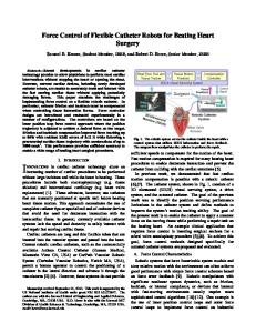
ment of the present invention. with three side electrodes and one end electrode; FIG. 2 is a fragmentary side elevational view of the tubing and wound wires thereof. to a slightly enlarged scale; FIG. 3 is a fragmentary sectional view taken along the line 3—3 of FIG. 2. to a greatly enlarged scale; PIGS. 4A-4D are schematics illustrating the process of applying the ?at ribbon to the tubing; FIG. Sis a fragmentary longitudinal sectional view of the
onto a respective one of the ?at means and the outer tubular
layer. Preferably. the core is a stranded con?guration of annealed stainless steel wire having an appreciable torsional strength and a slow return after lateral bending. The core
covering layer and the outer tubular layer are formed of
polyurethane. The core-covering layer is softer than the outer tubular layer. The core-covering layer is over-extruded
catheter after crimping of the ring electrodes thereon; FIG. 6 is a transverse sectional view thereof to an enlarged
over the core. and the outer tubular layer is over-extruded
scale. with the crimps being greatly exaggerated for exposi
over the wound wires and the core-covering layer. Where each of the wound wires is covered with electrical insulation. the electrical insulation covering each wound
tory purposes; FIG. 7 is a transverse fragmentary sectional view thereof
wire de?nes a removed section beneath one of the elec trodes. Preferably. the ?at means is a ?at copper ribbon having a
taken along the line 7-—7 of FIG. 5. to a greatly enlarged
scale. with the crimps being greatly exaggerated for exposi tory purposes;
pair of opposed ends. the ribbon being electrically and
FIG. 8 is a fragmentary exploded side elevational view of the catheter and end electrode assembly; and FIG. 9 is a side elevational view of the assembly of FIG.
physically joined at one end to a respective one of the wound
wires wrapped under tension completely about the outer tubular layer. and physically joined at the other end to itself. The ?at means is preferably joined to the wound wires by
8 after crimping. with the crimps being greatly exaggerated for expository purposes.
welding.
DETAILED DESCRIPTION OF THE PREFERRED EMBODIMENTS
Preferably. the electrodes are platinum with a minor
proportion of iridium. Each of the ring electrodes is crimped onto the ?at means and the outer tubular layer at at least 24
Referring now to FIG. 1. therein illustrated is an
crimp points. In a preferred embodiment. the ring electrodes
electrode-carrying catheter according to the present invention. generally designated by the reference numeral 10.
crimped onto the ?at means and the outer tubular layer are also welded to the ?at means. and the outer tubular layer is
reformed about the ring electrodes. Where the core has an extension projecting distally from the distal end. an electrically conductive end electrode is crimped distally onto the core extension and is proximally crimped onto and radially ?ush with the outer tubular layer.
While the con?guration and dimensions of the catheter will vary with the intended application for the catheter. it is generally of the same overall width and length of the known catheters for the same application. The catheter 10 is formed 35
of elongate. ?exible tubing generally designated 12. The tubing 12 defines a proximal end 14. a distal end 16. and a sidewall or outer tubular layer 20 connecting the ends 14. 16 and having an electrically insulative outer surface 21. Referring now to FIGS. 2-4 as well. at least one electrode 30 is disposed on the tubing 12. The electrode may be a side electrode 30a disposed on the outer surface 21 (three side electrodes being illustrated in FIG. 1). an end electrode 30b disposed on the distal or front end 16 (one end electrode being illustrated in FIG. 1). or a combination thereof.
The present invention also encompasses a process for
manufacturing an electrode-carrying catheter of high reliability. comprising the step of over-extruding a soft outer
layer of plastic over a ?exible. electrically conductive. elongate core of wire. A spaced apart plurality of ?exible. electrically conductive wires is helically wound about and at least partially into the soft outer layer. A ?exible. non conducting hard outer layer of plastic is over-extruded over the wound wires and the soft outer layer. Portions of the hard 45 Particular ring electrodes 30a may extend predominantly outer layer. and any insulation about the wound wires. are axially or transversely (i.e.. circumferentially) relative to the removed at a plurality of ed locations so as to expose a tubing axis as preferred for a given application. Preferably portion of each of the wound wires. The removed portions the side electrode 30a extends fully around the circumfer at each location are replaced with an electrically conductive
?exible ribbon electrically and physically joined to a respec~
ence of the tubing 12. and the end electrode 30b extends over 50
tive one of the wound wires and wound about the wound
wires and hard outer layer. An electrically conductive ring electrode is crimped onto each of the ribbons and the bard outer layer thereabout at each spaced location. ?ush with the
hard outer layer. the ribbons conducting electrical signals
posed initially of a ?exible. conductive core 42 and a
between a respective one of the exposed wire portions and a respective one of the ring electrodes.
?exible. insulating. soft. core-covering layer 44 disposed over the outer surface of the core 42. The soft or core
covering layer 44 may be formed by over-extruding (or
BRIEF DESCRIPTION OF THE DRAWING
The above and related objects. features. and advantages of the present invention will be more fully understood by reference to the following detailed description of the pres ently preferred. albeit illustrative. embodiments of the present invention when taken in conjunction with the
accompanying drawing wherein: FIG. 1 is a fragmentary side elevational view of an
electrode-bearing catheter according to a preferred embodi
the full diameter of the distal end 16 (as illustrated). Con ducting means. generally designated 29. are provided for conducting electrical signals between the proximal end 14 and each of the electrodes 30a. 30b. 30a. 30b. Referring now to FIGS. 2 and 3. the tubing 12 is com
otherwise forming) a soft plastic over the wire core 42. the 60
soft layer being relatively softer than the wire core. The core 42 is preferably formed of a wire exhibiting an appreciable degree of torsional sti?ness (so that rotation of the proximal end 14 of the tubing is transmitted to the distal end 16) and
65
catheter makes good contact along its length with the walls of the vessel into which it is inserted). A preferred core 42
a slow return or recovery after a lateral bending (so that the
is a 0.032 inch outer diameter length of a stranded and
Re. 35.924 5
6
twisted con?guration of annealed wire. such as 304 stainless
steel 7X19. (The annealing process involves heating the
mate locations of the side electrodes 30a) so as to form windows 47. Each window 47 exposes a portion of a
stainless steel wire—e.g.. to 2.0000 F.—so that it becomes formable and tends to retain a con?guration into which it is
respective one of the wound wires 45 at its respective location. The hard layer 20 can be removed at the desired
locations by various techniques such as cutting. skiving.
?exed without immediately springing back.) A preferred soft
drilling or grinding. but grinding or cutting is preferred as they are easy. quick and precise operations. The windows are preferably formed using a grinding wheel having a diameter
core-covering layer 44 is formed of a soft plastic such as polyurethane having a durometer hardness of 80A available under the trade name Teco?ex (from Thermedics Inc. of
suitable for forming windows of the desired size (such as a
Woburn. Mass.).
0.020 inch diameter) until the grinding has removed a suitable amount of the hard layer 20 and. where present. the
As part of the conducting means. ?exible. insulated. electrically conductive wires 45 (three wires 45a. 45b. 45c
insulation about the wire 45. so as to expose the conductive
being shown. one for each side electrode 30a) are helically or spirally wound around and at least partially into the soft core-covering layer 44 about the core 42. The wound wires 45 are longitudinally spaced apart such that each of the wires 45 is insulated from the two adjacent wires 45 by portions
element of the wire 45. Referring now to FIG. 8. in a similar fashion the hard
layer 20 at the distal end 16 of the tubing 12 is removed (e. g.. ground by a grinding wheel) in order to remove from the distal end 16 the hard outer layer 20 and. where present. the
of the soft layer 44 as well as the wire insulation. In order
insulation about the end of the core 42. Grinding of the distal
to preclude accidental movement of the spaced apart plu rality of wound wires 45 prior to over-extrusion of a hard layer 20 thereover. the wires 45 are helically or spirally
20
wound around the soft layer 44 (under roughly hand tension)
end 16 continues until there is exposed an appropriate length (about 0.035 inch) of the conductive element of the core
wire 42. this exposed conductive element projecting for
wardly from the distal end 16 of the tubing 12 as a core so that they at least partially embed themselves within the extension 42a soft layer 44 (preferably at least 75% of the diameter It will also be appreciated that the hard layer 20 of the becoming embedded). ‘The wound wires 45 are preferably sidewall 21 may have the portions at the particular locations 25 insulated magnet wires having a gauge of 34. As the soft removed therefrom simultaneously to form windows 47. layer 44 ensures electrical separation between the various The locations at which the hard layer 20 is to be removed are wires 45. the wires are not insulated in order to prevent predetermined by the desired location of the electrodes 30a. shorting if they come into contact. but merely to facilitate Before removal of the portions of the hard layer 20. the subsequent processing steps. Indeed. uninsulated wires may wound wires 45 are already in place and in ?xed spatial used if desired. It will be appreciated that. while only three 30 disposition relative to one another. Accordingly. once the wires 45 have been illustrated. the number of wires 45 can location of one wire 45 is determined (perhaps by inspection be varied as desired for particular applications depending on of the distal end 16 where they are initially visible). then the the number of side electrodes 30a. Each wire may be of a location of all of the remaining wires 45 is known. Thus. different color. grinding elements of a grinding machine. for example. can Finally. a ?exible. thin insulating layer of plastic is 35 be appropriately positioned relative to the known wire. and over-extruded (or otherwise formed) over the soft core the desired portions of the bard layer 20 (and. when present. covering layer 44 and any exposed portion of wound wires the wire insulation) simultaneously removed at each loca 45 to form the hard outer layer 20 of the tubing 12 de?ning tion. This enables the windows 47 to be inexpensively outer surface 21. The hard layer 20 may be formed of formed in a low labor operation. polyurethane or any of the other ?exible. but hard. electri Referring again to FIG. 4B. after creation of the windows
cally insulative plastics commonly used in catheter construc tion such as polyvinyl chlorides. polyesters and various copolyrners. The hard layer 20 is preferably formed of
polyurethane having a durometer hardness of 71D available under the trade name Tecothane (from Thermedics Inc.).
47. a ?at conductive element 51. such as a ?at copper ribbon
(0.00lX0.012 inch). is electrically and physically joined to 45
point 48 using a welder such as that available under the trade
Thus the conductive wires 45 are isolated from one other and
the environment by means of the core 42. the soft layer 44. and the hard layer 20 as well as any insulation thereon. The hard layer 20 is preferably over-extruded to a thick ness slightly greater than that ultimately desired so that it
the exposed portion of the wire 45 under the window 47. Preferably the ribbon 51 is welded to the exposed wire 45 at
name Light Force Welder (from Unitek Equipment Inc. of Monrovia. Calif). Typically. a free ribbon end 51a is ?rst
may be subsequently ground down (prefix-ably using a
welded to the wire 45. Referring now to FIG. 4C. the ribbon 51 and the tubing 10 are then rotated relative to one another until a shank 51b of the ribbon 51 is wrapped completely one turn (360°) about the hard layer 20. and back on itself. This
conventional centerless grinding machine) down to a con
may be accomplished by rotating the tubing 12 while using
50
stant outer diameter. thereby masking irregularities origi nally present due to the presence of the wires 45 wound on
the soft layer 44. If the soft core-covering layer 44 is of su?icient thickness to receive and electrically isolate the wound wires 45 (which must then be totally embedded therein) and is furthermore subsequently treatable (e.g.. curable or modi?able) to pro
a machine to maintain hand tension on the ribbon 51. Next. 55
the as yet unwelded ribbon end 51c of the loop thus formed is welded to the ribbon 51 at point 49 (preferably at the already welded ribbon end 51a). Finally. as seen in FIG. 4D.
the ribbon 51 is removed from the ribbon spool (not shown). e.g.. by simply applying a quick tug to the ribbon.
vide an abrasion-resistant surface. application of the hard
While there is an overlap of the ribbon 51c upon itself 51a. the extra thickness of the additional ribbon layer is of
layer 20 may be dispensed with entirely and the soft layer
no consequence since the ribbon is so thin relative to the
44. thus treated after the wires 45 are totally embedded depth of the window 47. It will be appreciated that the ribbon therein. will also serve as the hard layer 20. performs the role of bringing the signal from the exposed Referring now to FIG. 4A. next. the hard layer 20 of the 65 wire (which is located below the hard layer 20) up to the top of the hard layer 20 where it can be fed to an electrode 30a. tubing 12 is removed at a plurality of spaced locations along Preferably the Welding equipment uses the electrodes avail its circumferential sidewall 21 (corresponding to the ulti
Re. 35,924 7
8
able under the trade name Unitip lllL (available from Unitek Equipment Inc.) or a similar microelectrode which
As a highly-desirable by-product of the welding process. the heat generated thereby melts the hard layer 20 under neath the electrode 53. allowing it to reform and securely attach itself to the electrode 53. Accordingly. the electrode
permits the welding equipment to resistively weld the exposed wire 45 and the ribbon 51 together within the con?nes of window 47.
53 adheres better to the hard layer 20 as well as the ribbon
The application of the ribbon 51 to a wire 45 is then
51 and is less likely to separate therefrom during subsequent ?exure of the catheter. thus enhancing reliability of the
repeated for each of the remaining windows 47. and the tubing 12 is then ready for application of the ring or metal electrodes 30.
product. The manufacturing process of the present invention is in all its aspects easy and inexpensive relative to the labor intensive nature of most other manufacturing processes for producing an electrode carrying catheter. while affording a
Referring now to FIGS. 5-7. to form the side electrodes 30a. a metal band or ring electrode 53. preferably formed of a biocompatible metal such as platinum or an alloy of
platinum hardened with 10% iridium. is slid along the length
product of enhanced reliability.
of the hard layer 20 of tubing 12 to an appropriate location
Referring now to FIG. 8. where the catheter 10 includes
to cover one of the windows 47. The inner diameter of the
at least one end electrode 30b as one of the electrodes 30
ring electrode 53 is slightly larger than the outer diameter of
thereof. the electrically conductive end electrode is prefer
the tubing 12 to enable the electrode 53 to slide over the hard layer 20 and over the top of the ribbon 51 at the location. The
ably con?gured and dimensioned as a ?exible cap. generally designated 60. disposed across the distal end 16 of the mbing
length of each ring electrode 53 (0.078 inch) is greater than the length of the window 47 it covers. so that the ring electrode 53 also extends over the adjacent surfaces of the
12 in order to close the same. The cap 60 may be formed of 20
material. The cap 60 is of appreciable thickness and has a
hard layer 20. A crimping machine (not shown) is then employed to crimp the outer diameter of the ring electrode 53 down to the outer diameter of the tubing 12 (i.e.. the hard
layer 20). To this end. the crimping machine is provided with
a circumferentially spaced plurality of crimping points (for
head 64 defining a recess 62 on its proximal surface and a
proximally projecting circumferential band 66. As cap 60 is 25
to FIG. 9. the head or cap distal end 64 is then crimped onto the core extension 42a. at 80. and the band or cap proximal
circumference) which simultaneously crimp and collapse the band of electrode 53 to a preset diameter (e.g.. 0.078 inch) so that the crimped or collapsed band retains its original circular con?guration but with a reduced diameter.
end 66 is crimped onto and ?ush with the hard layer 20. at
82. This double crimping 80. 82. using a crimping machine as described hereinabove in connection with the crimping of
the side electrodes 30a. securely joins the end electrode 30b with the core extension 42a and hard layer 20. neither a 35
surfaces of the hard layer 20. The ribbon ends 51a. 51c and
the ring electrode 53 are typically spaced apart. electrical contact between ribbon 51 and ring electrode 53 being effected through ribbon shank 51b. It will be appreciated that. because the crimping operation squeezes the electrode band 53 ?ush with the tubing outer surface 21. an extremely smooth tubing/electrode interface is obtained without increasing the diameter of the tubing 12. Typically no subsequent hand smoothing of the exterior surface of the tubing at the tubing/electrode interface is
45
50
process which offers a signi?cant cost advantage over con ventional processes for producing a catheter with a ?ush
functioning. and all exposed surfaces being biocompatible. The catheter is easily and inexpensively manufactured. Now that the preferred embodiments of the present inven tion have been shown and described in detail. various modi?cations and improvements thereon will become readily apparent to those skilled in the Accordingly. the spirit and scope of the present invention is to be construed broadly and limited only by the appended claims. and not by the
foregoing speci?cation.
outer surface by sharply reducing labor requirements and simplifying assembly. While crimping of the side electrodes 53 on the tubing 12 su?ices to electrically and physically
ribbon 51 nor a welding step being required. As used herein. the terms “insulating”. “insulative”. “non conducting" and “non-conductive” are synonyms. To summarize. the present invention provides an electrode-carrying catheter of high reliability and low cost. the catheter being capable of mounting a large number of electrodes. There is reliable adhesive-free electrical contact between an electrode and any conductive wire extending from the proximal end to the electrode. with the electrode having a su?iciently large surface area for electrode
required. Accordingly. the present invention employs a crimping
slipped over the distal end. the core extension 42a is received within cap recess 62. and the distal end of the hard
layer 20 is received within the cap band 66. Referring now
example. 12 points equidistantly spaced about a
Preferably the crimping machine and the catheter worlqiiece are then relatively rotated (e.g.. 15°) and crimping is per formed a second time (thus maldng. for example. 24 equi distantly spaced crimp points). thereby to ?atten out any high spots left by the ?rst crimping. The length of each crimp is greater than the ribbon 51 so that each ring electrode 53 is crimped onto both ribbon 51 and the adjacent
the same material as the ring electrodes or a di?erent
I claim: 55
secure the electrode 53 to the ribbon 51 and hence to the
1. An electrode-carrying catheter. comprising: (A) elongate. ?exible tubing de?ning a proximal end. a
associated exposed wound wire 45. excessive bending of the
distal end. and an electrically insulative outer tubular
catheter during use may still result in a separation of elements enabling the electrode 53 to move relative to the ribbon 51 and hard layer 20. Accordingly. for extra security the ring electrode 53 is preferably ?nally Welded to the ribbon 51. The welding may be performed using a conven tional resistive welder with two electrodes which have been
layer intermediate said ends. said tubing including a
machined to the diameter of the electrode 53 so that the welder cannot damage the electrode under the pressure of 65 the weld. A preferred resistive welder is available under the
trade name Thin Line Welder (from Unitek Equipment Inc.)
?exible electrically conductive core of wire and a
?exible non-conductive core-covering layer of plastic about said core;
(B) at least one electrically conductive ring electrode crimped on and ?ush with said outer tubular layer. and (C) conducting means for conducting electrical signals between said proximal end and each of said at least one
ring electrode. said conducting means including. inter mediate said core and said outer tubular layer. a
Re. 35,924 10 layer intermediate said ends. said tubing including a
longitudinally-spaced plurality of ?exible electrically conductive wires helically wound around and at least
?exible electrically conductive core of wire and a
partially into said core-covering layer and insulated
?exible non-conductive core-covering layer of plastic
from one another at least by said core-covering layer and from the environment at least by said outer tubular
about said core. said core being a stranded and twisted
con?guration of annealed stainless steel wire having an appreciable torsional strength and a slow return aftcn'
layer. said outer tubular layer de?ning a removed
lateral bending. said core-covering layer being softer
section beneath a segment of each of said at least one ring electrode to enable electrical contact between a respective one of said wound wires and a respective one of said at least one ring electrode. said conducting
than said outer tubular layer and over-extruded over said core;
means further including electrically conductive ?exible
(B) at least one electrically conductive ring electrode crimped on and ?ush with said outer tubular layer; and
?at means disposed intermediate each of said at least
(C) conducting means for conducting electrical signals
one ring electrode and said tubing for providing elec
between said proximal end and each of said at least one
trical communication between one of said at least one
ring electrode and one of said wound wires. each of
ring electrode. said conducting means including. inter 15
said ?at means being electrically and physically joined to a respective one of said wound wires and wrapped about said outer tubular layer. each of at least one ring electrode being crimped onto a respective one of said ?at means and said outer tubular layer. 2. The catheter of claim 1 wherein said ?at means is
longitudinally-spaced plurality of ?exible electrically conductive wires helically wound around and at least
partially into said core-covering layer and insulated from one another at least by said core-covering layer 20
3. The catheter of claim 1. wherein said core-covering layer is softer than said outer tubular layer. 4. The catheter of claim 1. wherein said core-covering
ing a removed section beneath a segment of each of said at least one ring electrode to enable electrical contact between a respective one of said wound wires and a respective one of said at least one ring electrode.
layer is over-extruded over said core. and said outer tubular layer is over-extruded over said wound wires and said
said conducting means further including electrically
core-covering layer. 5. The catheter of claim 1. wherein said ?at means is a ?at
joined at the other end to itself. 6. The catheter of claim 1. wherein said core is a stranded and twisted con?guration of annealed stainless steel wire having an appreciable torsional strength and a slow return
and insulated from one another at least by said core
covering layer and from the environment at least by said outer tubular layer. said outer tubular layer de?n
joined to said wound wires by welding.
copper ribbon having a pair of opposed ends. said ribbon being electrically and physically joined at one end to a respective one of said wound wires. wrapped under tension completely about said outer tubular layer. and physically
mediate said core and said outer tubular layer. a
30
conductive ?exible ?at means disposed intermediate each of said at least one ring electrode and said tubing for providing electrical communication between one of said at least one ring electrode and one of said wound
wires. each of said ?at means being a ?at copper ribbon
having a pair of opposed ends. said ribbon being electrically physically joined by welding at one end to 35
a respective one of said wound wires. wrapped under tension completely about said outer tubular layer. and
physically joined by welding at the other end to itself. each of said at least one ring electrode being crimped
after lateral bending. 7. The catheter of claim 1 wherein said core-covering layer and said outer tubular layer are formed of polyure thane. 8. The catheter of claim 1 wherein each of said wound wires is covered with electrical insulation, and said electrical insulation covering each wound wire de?nes a removed
onto a respective one of said ?at means and said outer
tubular layer. said at least one ring electrode crimped onto sad ?at means and said outer tubular layer being also welded to said ?at means. and said outer tubular
section beneath one of said at least one electrode. 45 9. The catheter of claim 1 wherein said at least one
electrode are platinum with a minor proportion of iridium. 10. The catheter of claim 1 wherein each of said at least one ring electrode is crimped onto said ?at means and said
layer being reformed about said at least one ring electrode. said outer tubular layer being over-extruded over said wound wires and said core-covering layer. said core having an extension projecting distally from said distal. end and an electrically conductive and electrode being crimped distally onto said core extension and
proximally crimped onto and radially ?ush with said
outer tubular layer at at least 24 crimp points.
outer tubular layer. 11. The catheter of claim 1 wherein said at least one ring 15. The catheter of claim 14 wherein. said wound wires electrode crimped onto said ?at means and said outer tubular include electrical insulation thereabout. and said outer tubu layer are also welded to said ?at means. and said outm lar layer and said electrical insulation about said wound tubular layer is reformed about said at least one ring elec wires de?ne said removed section. trode. 55 16. An electrode-carrying catheter; comprising: 12. The catheter of claim 1 wherein said core has an
(A) elongate, ?exible tubing de?ning a proximal end, a
extension projecting distally from said distal end. and an electrically conductive end electrode is crimped distally onto said core extension and is proxirnally crimped onto and radially ?ush with said outer tubular layer. 13. The catheter of claim 1 wherein. said wound wires
distal end, and an electrically insulative outer tubular
layer intermediate said ends, said tubing including a ?eJa'ble electrically conductive core of wire and a
?en'ble non~conductive cone-covering layer about said cane;
include electrical insulation thereabout. and said outer tubu lar layer and said electrical insulation about said wound wires de?ne said removal section.
14. An electrode-carrying catheter. comprising: (A) elongate. ?exible tubing de?ning a proximal end. a distal end. and an electrically insulative outer tubular
(B) at least one electrically conductive ring electrode crimped on and flush with said outer tubular layer; and 65
(C) conducting means for conducting electrical signals between said prwdmal end and each of said at least one
ring electrode, said conducting means including, inter
Rc. 35,924 11
12 tubular Myer and said electrical insuMtion about said wound wires de?ne said removed section.
mediate said core and said outer tubuMr Myer; a
longitudinally-spaced plurality of ?exible electrically conductive wires helically wound around and at least
partially into said core-covering Myer and insulated from one another at least by said core-covering layer 5 andfrom the environment at least by said outer tubular Myer; said outer tubuMr layer de?ning a removed section beneath a segment of each of said at least one
29. An electrode-carrying catheter; comprising: (A) elongate, ?exible tubing de?ning a proximal end, a distal end, and an electrically insulative outer tubuMr
Myer intermediate said ends, said tubing including a flexible non-conductive core-covering layer about said core, said core being a stranded and twisted con?gu ration of annealed stainless steel wire having an appre ciable torsional strength and a slow return after Mteral
ring electrode to enable electrical contact between a respective one of said wound wires and a respective one
of said at least one ring electrode, said conducting
mean further including electrically conductive ?exible
bending, said core-covering layer being softer than
?at means disposed intermediate each of said at least one ring electrode and said tubing for providing elec
said outer tubuMr Myer and over-extruded over said core;
trical communication between one of said at least one 15
ring electrode and one of said wound wires, each of
(B) at least one electrically conductive ring electrode crimped on and?ush with said outer tubuMr layer; and
said ?at means being electrically and physically joined
(C) conducting means for conducting electrical signals
to a respective one of said wound wires, and wrapped about said outer tubuMr Myer; each of at least one ring electrode being crimped onto a respective one of said ?at means and said outer tubuMr layer: 17. The catheter of claim 16 wherein said ?at means is
joined to said wound wires by welding. 18. The catheter of claim 16 wherein said core-covering layer is softer than said outer tubuMr layer. 19. The catheter of claim 16 wherein said core-covering
between said proximal end and each of said at least one
ring electrode, said conducting means including, inter mediate said core and said outer tubuMr Myer; a
longitudinally-spaced plurality of ?exible electrically conductive wires helically wound around and at least
partially into said core-covering Myer and insulated 25
and insulated from one another at least by said core
cover'ing Myer and from the environment at least by said outer tubular Myer; said outer tubular Myer de?n ing a removed section beneath a segment of each of
Myer is over-extruded over said core, and said outer tubuMr
layer is over-extruded over said wound wires and said
core-covering layen
said at least one ring electrode to enable electrical contact between a respective one of said wound wires
20. The catheter of claim 16 wherein said flat means is a
flat copper ribbon having a pair of opposed ends, said ribbon being electrically and physically joined at one end to a respective one of said wound wires, wrapped under tension
and a respective one of said at least one ring electrode,
said conducting means further including electrically conductive ?exible ?at means disposed intermediate
completely about said outer tubular layer; and physically joined at the other end to itself:
35
21. The catheter of claim 16 wherein said core is a
stranded and twisted con?guration of annealed stainless
wires, each of said?at means being a ?at cooper ribbon
slow return after lateral bending. 22. The catheter of claim 16 wherein said core-covering Myer and said outer tubular Myer are formed of polyure
having a pair of opposed ends, said ribbon being electrically physically joined by welding at one end to a respective one of said wound wires, wrapped under tension completely about said outer tubular layer; and
thane.
23. The catheter of cMim 16 wherein each of said wound wires is covered with electrical insuMtion, and said electri
physically joined by welding at the other end to itself: 45
section beneath one of said at least one electrode.
24. The catheter of claim 16 wherein said at least one
electrode is pMtinum with a minor proportion of iridium. 25. The catheter of cMim 16 wherein each said at least one ring electrode is crimped onto said ?at means and said outer tubular layer at at least 24 crimp points. 26. The catheter of claim 16 wherein said at least one ring electrode crimped onto said flat means and said outer tubular Myer are also welded to said flat means, and said outer tubuMr layer is reformed about said at least one ring 55 electrode. 27. The catheter of cMim 16 wherein said care has an
extension projecting distally from said distal end, and an electrically conductive end electrode is crimped distally
each of said at least one ring electrode and said tubing for providing electrical communication between one said at least one ring electrode and one of said wound
steel wire having an appreciable torsional strength and a
cal insulation covering each wound wire de?nes aremoved
from one another at least by said core-covering Myer
each of said at least one ring electrode being crimped onto a respective one of said flat means and said out
tubuMr Myer; said at least one ring electrode crimped onto said ?at means and said outer tubuMr layer being also welded to said ?at means, and said outer tubular
Myer being reformed about said at least one ring electrode, said outer tubular layer being over-extruded over said wound wires and said core-covering Myer; said core having an extension projecting distally from said distal end and an electrically conductive end electrode being crimped distally onto said core exten sion and proximally crimped onto and radially flush with said outer tubuMr layer. 30. The catheter of claim 29 wherein said wound wires
include electrical insulation thereabout, and said outer onto said core extension and is crimpedproximally onto and 60 tubuMr Myer and said electrical insuMtion about said
radially ?ush with said outer tubular layen 28. The catheter of claim 16 wherein said wound wires include electrical insuMtion thereabout, and said outer
wound wires de?ne said removed section. *
*
*
*
*