2014 IEEE International Symposium on Information Theory
Elastic Routing in Wireless Networks With Directional Antennas Jangho Yoon1 , Won-Yong Shin2 , and Sang-Woon Jeon3 1
Electrical Engineering, KAIST, Daejeon 305-701, Republic of Korea Computer Science and Engineering, Dankook University, Yongin 448-701, Republic of Korea 3 Information and Communication Engineering, Andong National University, Andong 760-749, Republic of Korea Email:
[email protected];
[email protected];
[email protected] 2
Abstract— Throughput scaling law of a large wireless network equipping directional antennas at each node is analyzed based on the information-theoretic approach. More specifically, this paper considers a general framework in which the beamwidth of each node can scale at an arbitrary rate relative to the number of nodes in the network. We introduce an elastic routing protocol, which enables to increase per-hop distance elastically according to the beamwidth, while maintaining an average signal-to-interferenceand-noise ratio at each receiver as a constant. This elastic routing is shown to achieve a much better throughput scaling law than that of the conventional nearest-neighbor multihop routing. The gain comes from the fact that more source-destination pairs can be activated simultaneously as the beamwidth becomes narrower, which eventually leads to a linear throughput scaling law.
I. I NTRODUCTION In [1], the sum throughput scaling was originally introduced and characterized in a large wireless ad hoc network. It was shown that for the network having n nodes randomly distributed in a unit area, the total throughput scales as √ Ω( n/ log n) by conveying packets in a multihop fashion.1 There have been further studies based on multihop routing in the literature [2]–[4], while the total throughput scales far less than Θ(n). In [5], the throughput scaling was improved to an almost linear scaling, i.e., Ω(n1−ϵ ) for an arbitrarily small ϵ > 0, by using a hierarchical cooperation strategy. Besides the hierarchical cooperation scheme [5], there have been other research directions to improve the throughput of interference-limited networks up to a linear scaling by using node mobility [2], [6], interference alignment [7], infrastructure support [8], [9], and directional antennas [10]–[12]. To achieve such a linear scaling, there will be a price to pay in terms of higher delay [2], [5], [6], higher cost of channel estimation [5], [7], and high infrastructure investment [8], [9]. On the one hand, the use of directional antennas [10]–[12] in large wireless networks has recently emerged as a promising technology leading to the higher spatial reuse ratio, the improved transmission distance, and the reduced interference This research was supported by the Ministry of Science, ICT & Future Planning (MSIP), Korea in the ICT R&D Program 2013. 1 We use the following notation: i) f (x) = O(g(x)) means that there exist constants C and c such that f (x) ≤ Cg(x) for all x > c, ii) f (x) = o(g(x)) f (x) means that limx→∞ g(x) = 0, iii) f (x) = Ω(g(x)) if g(x) = O(f (x)), and iv) f (x) = Θ(g(x)) if f (x) = O(g(x)) and g(x) = O(f (x)).
978-1-4799-5186-4/14/$31.00 ©2014 IEEE
1001
level at a very low cost in comparison to alternative technologies. The previous work in the literature based on the protocol model [1] has shown that for an infinitely large antenna gain (or equivalently, for an infinitely small beamwidth), the use of directional antennas provides a substantial throughput enhancement up to a linear scaling [10]–[12]. It is however still unclear how much throughput scaling gain is achievable by directional antennas under a more realistic wireless channel. More precisely, the protocol model would not be suitable for dealing with the effects of directional antennas on the capacity since it does not reflect the physically attainable antenna gain that may be exploited in the presence of interference for given transmit power. In this paper, when there are n randomly located nodes in a large wireless ad hoc network equipping directional antennas at each node, we deal with a general framework where the beamwidth of each node, θ, can scale at an arbitrary rate relative to n. Similarly as in [10], [12], we take into account a simplified but feasible antenna model with both mainlobe and sidelobe gains. Then, we introduce a new routing, termed elastic routing, and analyze its throughput scaling law based on the information-theoretic approach. The routing protocol enables to increase the average transmission distance at each hop elastically according to the beamwidth, while setting the average signal-to-interference-and-noise ratio (SINR) at each receiver to a constant independent of n. Our main results indicate that the elastic routing can exhibit a much better throughput scaling law compared to the conventional nearestneighbor multihop routing. The gain comes from the fact that more source–destination (S–D) pairs can be activated simultaneously as the beamwidth θ becomes narrower, which eventually provides up to a linear throughput scaling. Interestingly, it is shown that when the total throughput is improved, the average delay gets reduced owing to this elastic routing, which is in sharp contrast with the omnidirectional mode (i.e., θ = Θ(1)). To see a possibility for further improving the throughput, a bursty hierarchical cooperation is also applied to our network with a slight modification. II. S YSTEM M ODEL We consider a two-dimensional wireless network consisting of n nodes that are distributed uniformly at random on a
2014 IEEE International Symposium on Information Theory
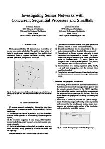
Fig. 1.
The beam pattern of our directional antenna model.
square. The nodes are grouped into n/2 S–D pairs at random so that each node is the destination of exactly one source. Each node operates in half-duplex mode and is equipped with a single directional antenna. The network area is assumed to be n and one in extended and dense networks, respectively. We define a hybrid antenna model whose mainlobe is characterized as a sector and whose sidelobe forms a circle (backlobes are ignored in this model).2 As illustrated in Fig. 1, the antenna beam pattern has a gain value Gm for the mainlobe of beamwidth θ ∈ [0, 2π), and also has a sidelobe of gain Gs of beamwidth 2π − θ. The parameters Gm and Gs are then related according to θ 2π − θ Gm + Gs = 1, 2π 2π
∑ i1 ∈I1
hki1 xi1 +
∑ i2 ∈I2
hki2 xi2 +
∑
S-D paths passing through their associated routing cells.
hki1 =
hki3 xi3 + nk ,
i3 ∈I3
(1) where xi1 , xi2 , and xi3 ∈ C are the signals transmitted by nodes i1 , i2 , and i3 , respectively, and nk denotes the circularly symmetric complex Gaussian noise with zero mean and variance N0 . The channel gains hki1 , hki2 , and hki3 are given by 2 Instead of directional antennas modeled as a cone in a three-dimensional view [10], [12], we use a rather simple two-dimensional antenna model since simplifying the shape of the antenna pattern will not cause any fundamental change in terms of capacity scaling law. 3 Note that G m = Gs = 1 in the omnidirectional mode.
1002
Gm ejϕki1 α/2
√ hki2 = hki3 =
where 0 ≤ Gs ≤ 1 ≤ Gm . In our work, we assume that Gm = Θ(1/θ) and Gs = Θ(1), which does not violate the law of conservation of energy.3 For simplicity, we assume unit antenna efficiency, i.e., no antenna loss. Nodes can use their antennas for directional transmission or directional reception, where the transmitter and receiver antenna gains are assumed to be the same. We also assume that each antenna is steerable, i.e., each node can point its antenna in any desired direction. Similarly as in [10], [12], suppose that a node i ∈ {1, · · · , n} transmits to another node k ∈ {1, · · · , n} \ i and they can beamform to each other according to our assumptions. Let I1 , I2 , and I3 denote three different sets of nodes transmitting at the same time as node i, where both nodes i1 ∈ I1 and k beamform to each other, either node i2 ∈ I2 or k beamforms to the other node (but not both), and neither node i3 ∈ I3 nor k beamforms to the other node, respectively. The received signal yk at node k ∈ {1, · · · , n} at a given time instance is given by yk =
Fig. 2.
,
(2a)
rki1
Gm Gs ejϕki2 α/2
,
(2b)
rki2 Gs ejϕki3 α/2
,
(2c)
rki3
respectively, where ϕki represents the random phase uniformly distributed over [0, 2π) and independent for different i, k, and time (transmission symbol), i.e., fast fading [5], [9], [13]. The parameters rki and α > 2 denote the distance between nodes i and k, and the path-loss exponent, respectively. Each node should satisfy an average transmit power constraint P , which is a constant, during transmission. Channel state information is assumed to be available at all the receivers, but not at the transmitters. We denote T (n) as the total throughput of the network, where each node is assumed to transmit at a rate T (n)/n on average. III. E LASTIC ROUTING P ROTOCOL In this section, we describe our elastic routing protocol, which can be designed with the help of directional antennas. Under the protocol, we perform multihop (or even single-hop) transmission by elastically increasing per-hop distance as a function of the scaling parameter θ, which ultimately enhances the throughput performance compared to the conventional multihop [1], [2]. We mainly focus on the extended network configuration, but the overall procedure of our protocol can be directly applied to the dense network scenario. We assume that M (n) S–D pairs, located randomly on the square, √ can be active simultaneously, where M (n) scales as Ω( n/ log n) and O(n) in our network model. Note that M (n) sources can generate their own data traffic at the same time. As depicted in Fig. 2, we divide the whole area into n/A(n) square routing cells with per-cell area A(n), where A(n) is assumed to scale as O(n) and Ω(log n). Let dhop and ¯ denote the average transmission distance at each hop and h the average number of hops per S–D pair, respectively. Then, it follows that (n) ( ) (3) A(n) = Θ d2hop = Θ ¯ 2 h
2014 IEEE International Symposium on Information Theory
in the extended network. We draw the straight line connecting a source to its destination, termed an S–D line. Then, packets for an S–D pair travel horizontally or vertically along its S–D line by hopping along adjacent cells of area A(n) until they reach the corresponding destination. While traveling along an S–D line, a certain node in each cell is arbitrarily selected as a relay forwarding the packets. Then, the antennas of each selected transmitter–receiver pair are steered so that their beams cover each other, which provides the highest received power along the line connecting the pair. In the extended network, full transmit power P is used at each node. Suppose that each routing cell with area A(n) is further divided into smaller square cells of area 2 log n, which guarantees that each smaller cell has at least one node with high probability (w.h.p.) (see [1] for the details). Only one node in each smaller cell is assumed to be a transmitter at the same time. As in [1], [2], all nodes operate according to the 9-time division multiple access (TDMA) scheme to avoid huge interference. This means that the total time is divided into 9 time slots and nodes in each smaller cell of area 2 log n transmit 1/9th of the time, while all transmitters in a smaller cell transmit simultaneously. Let us turn to how to decide the average per-hop distance dhop according to given beamwidth θ using the elastic routing. The parameter dhop can be elastically increased as much as possible while the average SINR at each receiver is set to Θ(1). This is the best we can perform along with packet forwarding schemes without loss of optimality in scaling since the total throughput is then given by T (n) = Ω(M (n)), assuming that M (n) S–D pairs are activated at the same time. In consequence, dhop can be determined according to the value of θ as follows:
√ which √ turns out to be scaled down by a factor of A(n) (= n), compared to the extended network case in (4). Since instead of the nearest-neighbor packet forwarding [1], packets can travel farther at each hop using this elastic routing ¯ can in the directional mode, the average number of hops, h, be reduced significantly, thereby resulting in the improved throughput up to a linear scaling, which will also be specified in the following section. IV. M AIN R ESULTS This section presents our main achievability result, which shows a throughput scaling law for both extended and dense networks using directional antennas. Unlike the existing analysis of scaling laws in [3]–[5], [9], it is hardly tractable to characterize a probabilistic bound on the throughput scaling. In our work, we first derive the average throughput E[T (n)], and then show that for any realization of the network (with random S–D pairings), the same throughput scaling as E[T (n)] is achievable w.h.p. based on the concentration analysis. A. Throughput Scaling in Extended Networks In this subsection, the throughput scaling for extended networks under the elastic routing protocol is shown. First, let SINRlk(p,l) denote the SINR value seen by receiver k(p,l) for the lth hop of the pth S–D pair, where l ∈ Hp and ¯ denotes the p ∈ {1, · · · , M (n)}. Here, Hp = {1, 2, · · · , βp h} set of hops for the pth S–D path, where βp > 0 is a parameter that scales as O(1). Then, we have k
SINRlk(p,l) = k
Pr (p,l) k
N0 + PI (p,l)
,
(6)
k
where Pr (p,l) and PI (p,l) denote the received signal power at node k(p,l) from the desired transmitter i(p,l) for the lth hop of the pth S–D pair and the total interference power at node k(p,l) from all interfering nodes, respectively. To be specific, from (2), they can be expressed as ( ) G2m k(p,l) 2 Pr = |hk(p,l) i(p,l) | P = Ω (7) dα hop
dhop (( )1/4 ) ) (√ n −1 if θ =o Θ log n log n (( ) (( 1 ) )1/4 ) α −2 2(α−1) (log n) n −1 α−1 θ if θ =Ω Θ n log n (( = )α/4) n −1 and θ =o log n (( )α/4 ) √ n and −1 if θ =Ω Θ( n) log n ( ∑ ( { { }) } k(p,l) 1 ( ) PI =P |hk(p,l) i1 |2 √ √ −2 (log n)α 2(α−1) α−1 = Θ min max log n, θ , n , i1 ∈I1 \{i(p,l) } n ) ∑ ∑ (4) 2 2 + |hk(p,l) i2 | + |hk(p,l) i3 | √ i2 ∈I2 i3 ∈I3 which will be verified later. Note that dhop = Θ( log n) in the omnidirectional mode (i.e., θ = Θ(1)). ∑ ∑ ∑ = O G2m + Gm Gs + G2s , In the dense network, a transmit power of P (log n/n)α/2 i2 ∈I2 i3 ∈I3 is used at each node. Then, it follows that i1 ∈I1 \{i(p,l) } (8) dhop ( { {√ } }) ( ) α respectively. Before establishing our main result, we start from −2 log n log n 2(α−1) α−1 , = Θ min max θ ,1 , the following lemma, which shows an upper bound on the n n average amount of the maximum among all the interference (5) powers at the receivers over an S–D path.
1003
2014 IEEE International Symposium on Information Theory
Lemma 1: Consider the pth S–D pair whose packets travel ¯ hops from a source to its destination, where p ∈ over βp h ¯ denotes the average number of hops {1, · · · , M (n)} and h per S–D pair. Then, when the 9-TDMA scheme is used, the expectation of the maximum among the interference powers ¯ undergo that all the receivers in the set Hp = {1, 2, · · · , βp h} is upper-bounded by [ ] ( { }) k ¯ , E maxPI (p,l) = O min θ−2 , h (9) l∈Hp
where the expectation is taken over M (n) randomly located S–D pairs. Proof: Refer to our full paper [14]. Now, we are ready to derive the total throughput in the following theorem when our elastic routing protocol is used in the network. Theorem 1: In the extended network, the total throughput achieved by elastic routing is given by (( )1/4 ) ( 1/2−ϵ ) n −1 if θ =o Ω n log n (( ( α−2 ) )1/4 ) 2 n Ω n 2(α−1) −ϵ θ− α−1 if θ−1=Ω log n (( T (n) = )α/4 ) n −1 and θ =o log n (( )α/4 ) ( ) n if θ−1=Ω Ω n1−ϵ log n (10) w.h.p., where ϵ > 0 is an arbitrarily small constant. Proof: A brief sketch of the proof is only provided. First, using (6) and (7), the average (mean) throughput per S–D pair can be lower-bounded by [ )] ( E min log 1 + SINRlk(p,l) l∈Hp [ ( )] k Pr (p,l) = E min log 1 + k l∈Hp N0 + PI (p,l) c G2 0
≥ E min log 1 + l∈Hp
= E log 1 +
k
N0 + PI (p,l) c0 G2m dα hop
N0 +
≥ log 1 +
m
dα hop
k maxPI (p,l) l∈Hp
c0 G2m dα hop
[
k
N0 + E maxPI (p,l)
]
l∈Hp
c0 θ−2 d−α hop { ≥ log 1 + √ } , N0 + c1 min θ−2 , d−1 n hop
(11)
where dhop is given by (4) and c0 and c1 are some positive constants. Here, the second inequality holds by Jensen’s inequality since log(1 + a/x) is convex in x for all a > 0. The
1004
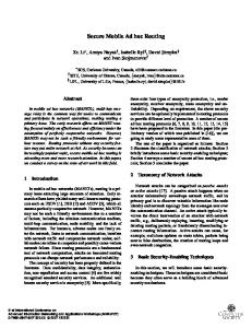
(a) 2 < α < 3
(b) α > 3
Fig. 3. The achievable throughput scaling T (n) with respect to the inverse of the beam width (1/θ).
last inequality comes from Lemma 1 and (3). By substituting (4) into (11), it follows that4 [ ( )] l E min log 1 + SINRk(p,l) = Ω(1). l∈Hp
From the fact that there exist √ ) ( ) ( dhop n n M (n) = Θ ¯ =Θ log n h log n active S–D pairs in the network, the average sum throughput E[T (n)] is lower-bounded by the result in (10) using (4). Thereafter, based on Chernoff’s theorem [15, Theorem 9.3], we can show that the total throughput T (n) scales at the same rate as the mean throughput E[T (n)] w.h.p., which indicates that any deviation of T (n) from its mean scales slower than T (n). More { specifically, it follows that, for } a sufficiently small 1 δ > 0, Pr M (n) |T (n) − E[T (n)]| ≥ δ approaches zero for large n. This completes the proof of the theorem. The total throughput scaling T (n) is illustrated in Fig. 3 according to the scaling parameter 1/θ (the terms ϵ and log n are omitted for notational convenience). If the parameter 1/4 θ−1 scales slower than (n/ log n) , then the achievable throughput scaling does not increase even with directional antennas and the same throughput as that achieved by the pure multihop [1] in the omnidirectional mode is obtained. α/4 On the other hand, if θ−1 scales faster than (n/ log n) , then an almost linear throughput scaling is possible in the network, which is consistent with the main result (including the beamwidth scaling condition) based on the protocol model [12]. The other beamwidth scaling condition bridges √ the total throughput T (n) between n and n. Our result is thus general in the sense that the achievable scheme and its throughput are shown for all operating regimes with respect to θ (i.e., for an arbitrary scaling of θ). The following interesting observations are also found. Remark 1: An improved total throughput leads to a delay reduction owing to the elastic routing, whereas, by using the conventional multihop scheme in the omnidirectional mode, the average delay increases proportionally with throughput T (n) [2]. Remark 2: For comparison, let us consider an ideal antenna model. It can be straightforwardly shown that Lemma 1 also 4 The throughput degradation up to a polylogarithmic term, coming from a power limitation, is omitted since it is negligible.
2014 IEEE International Symposium on Information Theory
holds when there is no sidelobe gain [10], [11], i.e., Gs = 0. This reveals that under this ideal model, the total throughput T (n) is given by (10) as long as Gs = O(1), and therefore, the existence of a sidelobe beam, whose gain scales as O(1), does not cause any performance loss in scaling law. B. Throughput Scaling in Dense Networks We now analyze the throughput scaling for dense networks under the elastic routing protocol. From the fact that Lemma 1 also follows in dense networks, the following theorem establishes our second main result. Theorem 2: In the dense network, the total throughput achieved by elastic routing is identical to the extended network case. Proof: In the dense network, by following the same argument as (11), the average throughput per S–D pair is lower-bounded by [ ( )] l E min log 1 + SINRk(p,l) l∈Hp )α/2 ( n c2 θ−2 dlog 2 n hop { } ≥ log 1 + −1 −2 N0 + c3 min θ , dhop which is proved to scale as Ω(1), where dhop is given by (5) and c2 and c3 are some positive constants. Hence, the total throughput is finally bounded by (10). As in the achievability result based on the nearest-neighbor multihop in the omnidirectional mode [1], note that when the elastic routing is used in the network, the total achievable throughput for the dense network is the same as the extended network scenario for all operating regimes with respect to θ. V. D ISCUSSION : T HE U SE OF H IERARCHICAL C OOPERATION In this section, we first examine whether or not using hierarchical cooperation [5] leads to a performance improvement on the throughput scaling law shown in Section IV. We focus only on the extended network model since in dense networks, hierarchical cooperation achieves an almost linear scaling even in the omnidirectional mode, which is the best we can hope for. An overview of the procedure of hierarchical cooperation is briefly shown as follows. • The network is divided into clusters each having M nodes. • (Phase 1) Each source in a cluster transmits its packets to the other M − 1 nodes in the same cluster. • (Phase 2) A long-range multiple-input multiple-output (MIMO) transmission is performed between clusters having a source and its destination. • (Phase 3) Each node quantizes the received observations and delivers the quantized data to the rest of nodes in the same cluster. By collecting all quantized observations, each destination can decode its packets.
1005
When each node transmits data within its cluster, it is possible to apply another smaller-scaled cooperation within each cluster by dividing each cluster into smaller ones. We recursively apply this procedure. Similarly as in [5], [13], in particular, we use a bursty hierarchical cooperation, which runs the scheme a fraction { } max θ−2 , n nα/2 { } of the time with instantaneous power of P max θ−2 , n at each node. In this case, note that we cannot fully utilize the power gain (i.e., the antenna gain) from the use of directional antennas. This is because a transmitter in a cluster and only an extremely small subset of receivers (but not all receivers) in another cluster can beamform to each other for the MIMO transmission in Phase 2 while the received interference power is always unbounded when θ = o(1). In consequence, the use of directional antennas may not be helpful in improving the throughput scaling compared to the omnidirectional mode. We refer to [14] for more details. R EFERENCES [1] P. Gupta and P. R. Kumar, “The capacity of wireless networks,” IEEE Trans. Inf. Theory, vol. 46, no. 3, pp. 388–404, Mar. 2000. [2] A. El Gamal, J. Mammen, B. Prabhakar, and D. Shah, “Optimal throughput-delay scaling in wireless networks-Part I: The fluid model,” IEEE Trans. Inf. Theory, vol. 52, no. 6, pp. 2568–2592, Jun. 2006. [3] M. Franceschetti, O. Dousse, D. N. C. Tse, and P. Thiran, “Closing the gap in the capacity of wireless networks via percolation theory,” IEEE Trans. Inf. Theory, vol. 53, no. 3, pp. 1009–1018, Mar. 2007. [4] W.-Y. Shin, S.-Y. Chung, and Y. H. Lee, “Parallel opportunistic routing in wireless networks,” IEEE Trans. Inf. Theory, vol. 59, no. 10, pp. 6290–6300, Oct. 2013. [5] A. Özgür, O. Lévêque, and D. N. C. Tse, “Hierarchical cooperation achieves optimal capacity scaling in ad hoc networks,” IEEE Trans. Inf. Theory, vol. 53, no. 10, pp. 3549–3572, Oct. 2007. [6] M. Grossglauser and D. N. C. Tse, “Mobility increases the capacity of ad hoc wireless networks,” IEEE/ACM Trans. Networking, vol. 10, no. 4, pp. 477–486, Aug. 2002. [7] V. R. Cadambe and S. A. Jafar, “Interference alignment and degrees of freedom of the K-user interference channel,” IEEE Trans. Inf. Theory, vol. 54, no. 8, pp. 3425–3441, Aug. 2008. [8] A. Zemlianov and G. de Veciana, “Capacity of ad hoc wireless networks with infrastructure support,” IEEE J. Select. Areas Commun., vol. 23, no. 3, pp. 657–667, Mar. 2005. [9] W.-Y. Shin, S.-W. Jeon, N. Devroye, M. H. Vu, S.-Y. Chung, Y. H. Lee, and V. Tarokh, “Improved capacity scaling in wireless networks with infrastructure,” IEEE Trans. Inf. Theory, vol. 57, no. 8, pp. 5088–5102, Aug. 2011. [10] S. Yi, Y. Pei, S. Kalyanaraman, and B. Azimi-Sadjadi, “How is the capacity of ad hoc networks improved with directional antennas?” Springer Wireless Netw., vol. 13, no. 5, pp. 635–648, Oct. 2007. [11] G. Zhang, Y. Xu, X. Wang, and M. Guizani, “Capacity of hybrid wireless networks with directional antenna and delay constraint,” IEEE Trans. Commun., vol. 58, no. 7, pp. 2097–2106, Jul. 2010. [12] P. Li, C. Zhang, and Y. Fang, “The capacity of wireless ad hoc networks using directional antennas,” IEEE Trans. Mobile Comput., vol. 10, no. 10, pp. 1374–1387, Oct. 2011. [13] A. Özgür, R. Johari, D. N. C. Tse, and O. Lévêque, “Informationtheoretic operating regimes of large wireless networks,” IEEE Trans. Inf. Theory, vol. 56, no. 1, pp. 427–437, Jan. 2010. [14] J. Yoon, W.-Y. Shin, and S.-W. Jeon, “Elastic routing in wireless networks with directional antennas,” in preparation. [15] P. Billingsley, Probability and Measure. John Wiley & Sons, Inc., 1995.