US006617774B1
(12)
United States Patent
(10) Patent N0.:
K s n0k1 et al
45 Date of Patent‘
u
(54)
u
'
.
Se
.
.
9, 2003
THIN-FILM ELECTRON EMITTER DEVICE
5,990,605 A
HAVING MULTLLAYEREI) ELECTRON
6,316,873 B1 * 11/2001 Ito et al. ................... .. 313/309
EMISSION AREAS
(75)
US 6,617,774 B1
* 11/1999 Yoshikawa et al. ....... .. 313/309
FOREIGN PATENT DOCUMENTS
Inventors: Toshiaki Kusunoki, TokoroZaWa (JP); Mutsumi Suzuki, Kodaira (JP)
JP JP
4-289644 7-65710
10/1992 3/1995
JP
10-92299
4/1998
(73) Assignee: Hitachi, Ltd., Tokyo (JP) * cited by examiner
(*)
Notice:
Subject to any disclaimer, the term of this patent is extended or adjusted under 35
U.S.C. 154(b) by 0 days.
(21) Appl. N0.: 09/546,690 (22) Filed: Apr. 10, 2000 (51)
Primary Examiner—Nimeshkumar D. Patel
Assistant Examiner—Sikha Roy (74) Attorney, Agent, or Firm—Mattingly, Stanger & M91119 PC (57) ABSTRACT
(52)
Int. c1.7 ............................ .. H01J 1/30; H01J 9/02; H01L 29/06 US. Cl. ..................... .. 313/311; 313/496; 313/306;
In Order to provide a thin-?lm electron emitter device of a structure Wherein electric connection betWeen a top elec node and top electrode busline can be Secured and also to
313/326; 257/10
provide a display apparatus using the thin-?lm electron
(58)
Field of Search ............................... .. 313/306 310
emitter device’ the top electrode busline thin on its Connec'
313/311 309 495 326 444 496. 2157/10’ ’
(56)
’
’
’
’
’
tion side With the top electrode is formed on a ?eld insulator Which is thicker than an insulator forming electron emission
References Cited
areas and Which is formed around the insulator, and the top electrode covers the top electrode busline to be connected
U-S~ PATENT DOCUMENTS 8/1999
With said thin part of said top electrode busline.
5,936,257 A
*
5,962,959 A
* 10/1999 Iwasaki et a1. ........... .. 313/310
Kusunoki et al. ........... .. 257/10
15B 14
13
16 Claims, 24 Drawing Sheets
12
15A 11
158 5A
U.S. Patent
Sep. 9, 2003
Sheet 1 0f 24
US 6,617,774 B1
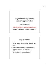
FIG. 1 (PROCESS PI BASE ELECTRODE PATTERNING (FIGS.2a-2b)
)
(PROCESS P2 ANODIC OXIDATION OF TUNNELING INSULATOR (FIGS. 3a-3D)
)
T (PROCESS P3 PHOTORESIST R1 PATTERNING (FIGS. 461-411)
)
I (PROCESS P4 ANODIC OXIDATION OF FIELD INSULATOR (FIGS.5a-5b) I
)
(PROCESS P5 PROTORESIST R2 PATTERNIIIO (FIGS. 6a-6b)
)
(PROCESS P6 LOWER TOP ELECTRODE BUSLINE FILM DEPOSITION (FIGS. 7a-7b)
v
( PROCESS P7 LIFT OFF PATTFERNING OF LOWER TOP ELECTRODE BUSLINE (FIGS. 8a-8b)
@IOCESS P8 PHOTORESISF R3 PATTERNING (FIGS. 9a-9b)
)
(PROCESS P9 UPPER TOP EILECTRODE BUSLINE FILM DEPOSITION (FIGS. IOa-IOb)
)
)
T (PROCESS P10 LIFT OFF PATTERNING OF UPPER TOP ELECTRODE BUSLINE (FIGS. IIa-IIDI) V
( PROCESS P11 PROTORESIST R4 PATTERNING (FIGS. 12a-12b)
)
(PROCESS P12 UPPER TOP ELECTRODE BUSLINE FILM DEPOSITION (FIGS. 13614311) I)
(PROCESS P13 PROTORESIST R5 PATTERNING (FIGS. 14a-14b)
I)
(PROCESS P14 ETCHING OF UPPER TOP ELECTRODE BUSLINE (FIGS. 15a-1Sb)
( PPIOCESS P15 PROTORESIST R6 PATTERNING (FIGS. I6a-16b)
I)
I
(PROCESS P16 TOP ELECTRODE FILM DEPOSITION (FIGS. I7a-I7b) I (PROCESS P17 LIFT OFF PATTEFINING OF TOP ELECTRODE (FIGS. I8a-I8b)
)
) )
U.S. Patent
IHB
US 6,617,774 B1
FIG. 2a
FIG. 2b
FIG. 3a
FIG. 3b
-—HIB
U.S. Patent
Sep. 9, 2003
Sheet 3 0f 24
FIG. 4a 2}
US 6,617,774 B1
FIG. 4b
@J/ R‘
12R
R1
\
% \\
we --@—---—&—--—IVB
5
I.
m
FIG. 5a
SE§\ VB
E5
FIG. 5b
é
11
U.S. Patent
Sep. 9, 2003
Sheet 4 0f 24
US 6,617,774 B1
FIG. 6b
FIG. 6a
R2 12
I I
VIB ——-~ "1’l
FIG. 7a
\ §W .
15A
m M BV V
_ X \m
\A \ \m x \m x 7
&(\70
.Mn. / i \1\
.1
\ R 2
% [11
U.S. Patent
Sep. 9, 2003
Sheet 5 0f 24
US 6,617,774 B1
FIG. 8b
FIG. 9a
FIG. 9b R3
15A
m M
11
U.S. Patent
Sep. 9, 2003
Sheet 6 6f 24
US 6,617,774 B1
FIG. 10a
FIG. 1013
R3
/%////////////////M42,
////
‘k
/
R3
\
/
/
§g
\
/.
WAVAVAV /
WWW 158
FIG. 11a .4
FIG. 11b
15A
B6%
15B
15A 12
V/
U.S. Patent
Sep. 9, 2003
Sheet 7 0f 24
US 6,617,774 B1
F/G. 12a
F/G. 12b 15A
J
R4
l\ l < 1
R4
12
XIIB —
K
I.
§ 10
FIG. 13a ,4
FIG. 13b
7/ ////////////////////l§//////////// % / % l
l
l\
l
PEB-
% 15A \p‘ld
>25
é¢/////////////////////// ///// %% 15B
14
15A
&\
7
10
U.S. Patent
Sep. 9, 2003
FIG. 14a
Sheet 8 0f 24
US 6,617,774 B1
FIG. 14b
WWW/i7 AVW/I/
FIG. 15a
V7
/’ u
15?
FIG. 15b
U.S. Patent
Sep. 9, 2003
Sheet 9 0f 24
US 6,617,774 B1
F/G. 16a 158 12
FIG. 16b R6
15A 15B
El
11
12
15A
\..§%@.
14
10J FIG. 17a 12
55 15A 56
FIG. 17b
gx\ \
‘////////// ///// //// //////// 14
§x\ \ \
\\
/ / / / / / / /
U3
U.S. Patent
Sep. 9, 2003
Sheet 10 0f 24
FIG. 18a
US 6,617,774 B1
FIG. 18b 15A 11
Iunn
7
m
FIG. 19
U.S. Patent
Sep. 9, 2003
Sheet 11 0f 24
US 6,617,774 B1
FIG. 20 ( PROCESS P21 BASE ELECTRODE PATTERNING (FIGS. 2a-2b)
)
(PROCESS P22 ANODIC OXIDATION OF TDNNELING INSULATOR LAYER (FIGS. Sea-Cw
(PROCESS P23 PHOTORESIST R11 PATTERNING (FIGS. 21a-21b)
CPROCESS P24 PHOTORESIST R12 PATTEIIINING (FIGS. 22a-22b) (PROCESS P25 ANODIC OXIDATION OF FIELD INSULATOR (FIGS. 23a—23b)
(PROCESS P26 LOWER TOP ELECTRODE BIISLINE DEPOSITION (FIGS, 24a—24b) I (PROCESS P27 LIFT OFF OF PHOTORESIST R12 (FIGS. 25a-25b)
I (PROCESS P28 PHOTORESIST R13 PATTERNING (FIGS. 26a—26b) I CPROCESS P29 UPPER TOP ELECTRODE BUSLINE DEPOSITION (FIGS. 27a-27b)
I (PROCESS P30 LIFT OFF OF PHOTORESIST R13 (FIGS. 288-28b)
I (PROCESS P31 TOP ELECTRODE DEPOSITION (FIGS. 29a~29b) I QPROCESS P32 LIFT OFF OF PHOTORESIST R11 (FIGS. 30a—30b)
VU Q
U.S. Patent
Sep. 9, 2003
Sheet 12 0f 24
US 6,617,774 B1
FIG. 21a
FIG. 21b
FIG. 22a
FIG. 22b
XXIB
R12
kg XXHB ———--@-—-——--%—-—xxns
@1
kgf /11
U.S. Patent
Sep. 9, 2003
Sheet 14 0f 24
US 6,617,774 B1
FIG. 25a
FIG. 25b
FIG. 26a
FIG. 26b
R11
R13
4%, \&
12
§/
11
U.S. Patent
Sep. 9, 2003
Sheet 15 0f 24
US 6,617,774 B1
FIG. 27a R11
FIG. 27b
Dn 3
7% /////////////////////////
A
R13 5B
V
////////////////
15A
&r)
158
FIG 28a
FIG. 28b
R11
,2 %/Z % XVHIB
158
J
U.S. Patent
Sep. 9, 2003
Sheet 16 0f 24
US 6,617,774 B1
FIG. 29a R11
FIG. 29b
15A
15B
13
/
V/7& %E
/ / / / / / / / / / / / / / / / / / /
%-% .Z.
FIG. 3019
15A
U.S. Patent
Sep. 9, 2003
Sheet 17 0f 24
US 6,617,774 B1
FIG. 31 12
13
15B
/15A
FIG. 32 (PROCESS P33 BASE ELECTRODE PATTERNING (FIGS. 33a-33c)
)
(PROCESS P34 FIELD INSULATOR FORT/TAILOR (FIGS. 348~34CI
)
@ROCESS P35 TUNNELING INSULATOR FORMATION (ROS. 35a-35c)
)
(PROCESS P36 TOP ELECTRODE BUSLINEIFILM DEPOSITION (FIGS. 36a—36c) @ROCESS P37 WET ETCHING OF UPPER TOP ELECTRODE BUSLINE FILM (FIGS.37a-37CD
(PROCESS P38 wET ETCHING OF LOwER TOiP ELECTRODE BUSLINE FILM (FIGS.38a-38CD (PROCESS P39 TOP ELECTRODE DEPOSITION AND PATTERNING (FIGS. 3921-390) J
U.S. Patent
Sep. 9, 2003
US 6,617,774 B1
Sheet 18 0f 24
11
FIG. 33a
V/A WM
FIG. 33b XXXHIB
F/G. 330 W
g/é. /é // / %
f
R21
14
FIG. 34a T]
FIG. 3419
$7
R21
14
XXXIVB
FIG. 34c
$
Q,_\ J R21
xxmvA—---—§——--@ XXXIVB
-— XXXIVA
-P\V14