The WebTP Architecture and Algorithms Ye Xia∗ Hoi-Sheung Wilson So Venkat Anantharam Steven McCanne David Tse Jean Walrand Pravin Varaiya Department of Electrical Engineering and Computer Science University of California, Berkeley
Abstract Motivated by the increasing popularity of the Web-based applications, we have designed a new transport protocol, called WebTP, that is suitable for today’s complex network environment. Leveraged on the research work in the past decade on TCP and UDP, our transport protocol integrates and implements various recommendations for protocol improvement. It is a general-purpose protocol that promises to improve the performance of a diverse class of applications, including short-interactive transactions, bulk file transfer, real-time and nonreal-time media streams. It supports fine-grained and application-specific control, which includes: application-level framing (ALF), reliability control at the level of application data unit (ADU) and user-centric bandwidth management. In WebTP, the network condition is constantly monitored and is visible to the application through a set of application programming interface (API). The applications can adapt to the time-varying network condition. The connection-oriented protocol has a fast option that bypasses connection setup in a controlled fashion and can improve the response time for interactive connections. WebTP uses an abstraction, called pipe, which is the communication channel between a pair of IP end-hosts. Because many connections between the IP pair can be multiplexed into the pipe, the resulting traffic becomes smoother and can be more readily controlled. Moreover, due to the concentration of the available bandwidth, quality-of-service (QOS) provision becomes possible through differentiated treatment toward the connections within each pipe. Specifically, the pipe bandwidth is allocated to the connections through a scheduler that provides bandwidth-guaranteed service, delay-guaranteed service and best-effort service jointly. In the paper, we contrast our end-to-end, layer-4 approach to QOS provision with those layer-3 approaches. In the area of congestion control, our goal is to speed up the start-up phase of a pipe while reducing protocol-induced packet losses, as compared with TCP. We achieve this by enhancing the window-based congestion control with the help of the observed rate information. Keywords: architecture, protocol, transport protocol, QOS, application-level framing, scheduling, congestion control, reliability control, TCP, UDP, bandwidth allocation, slow start, congestion avoidance, pipe, ADU
∗
This project is funded by NSF Award #9872764.
1
1 1.1
Introduction History of the WebTP Project
The objective of the WebTP project is to optimize the performance of web-based applications based on the user’s preferences. Consider the following single-user scenarios. Example 1 Suppose the user makes a request to retrieve a familiar web page that contains numerous objects, such as images and blocks of text. Assume that he is allocated some fixed bandwidth in the network path. Hence, the total transfer time for the web page is fixed. If the user’s satisfaction depends only on the time when the entire page is received, then very little can be done to improve his satisfaction. However, it is reasonable to assume that each object in the web page has certain value to the user, and the user receives certain utility as he receives each object. The user can then exploit the differences in the values of the objects. For instance, he might prefer to order the object transfer in such a way that gives him the most utility at any fixed time. In practice, the user can specify either the utility or the transfer order at various degrees of precision based on the knowledge he has about the page, or based on his general knowledge about a large number of similar pages. Alternatively, if the user has no information about the page and cannot specify his preferences a priori, the server may know what an average user prefers based on its experiences with a large number of users. In a separate paper [30], we have systematically explored the computational aspect and application-level implementation for ordering the transmission of objects to improve the user’s satisfaction. In this paper, we present the transport support required by such a feature. Example 2 Suppose the user opens a connection to a CNN server and receives video programming, and at the same time browses the CNN web site. The user prefers to receive the video at the required bandwidth and use the leftover bandwidth for browsing. Later, the user decides that a smaller video window suffices. He adjusts the bandwidth assigned to each connection by using a separate bandwidth control application. Transport mechanisms and their associated APIs are required for the user to statically or dynamically allocate bandwidth to his connections. This scenario applies to information delivery/retrieval from rich content servers. A slightly more general scenario can also take advantage of such transport mechanisms. While watching the CNN video news, the user browses web pages on different servers located in different geographical areas. All connections are bandwidth-limited at the same link in the network, which might be the user’s access line to the Internet, or a line at his Internet Service Provider’s access network. Example 1 and 2 are single user scenarios in which the total bandwidth allocated to the user is fixed. Optimization takes place when the user trades off bandwidth assigned to each of his connections or when he arranges the transmission orders of objects within a single connection. Initially, the WebTP project is aimed primarily at the single-user optimization problem in which the resource limitation is the user’s access line [13]. Improvement in the Internet access speed with the help of DSL or cable modem does not diminish the importance of this optimization by much. Firstly, the fast growing wireless data services mainly rely on low-speed transmission technology. Secondly, we have shown in [30] that the Smallest-ObjectFirst transmission schedule leads to significant performance improvement perceived by the user even at the access speed of 380 Kbps and 1.5 Mbps. Furthermore, as the speed of access lines increases, the web contents also scale up their bandwidth requirement. Today’s fastest access
2
line speed is still far below what is required by the full-motion picture. The need to trade-off bandwidth assignment to different connections will still be there for very high speed Internet access. Transport support for user-centric optimization has led us through a critical investigation of the transport functions. We have found that TCP and UDP lack some important features that can support some obvious optimization in data transmission. New transport provisions needed to support single-user optimization also support multi-user optimization, where the optimization criterion is the total user-satisfaction for all users bottlenecked at the same link in the network. Multi-user optimization is closely related to the notion of quality-of-service (QOS) guarantee. Roughly, an optimizing service must guarantee the required service quality for every user when the network resource permits. When the network resource is insufficient, some connections should not be admitted for service and the QOS should be guaranteed for the admitted connections. An optimizing approach for the admission decision should admit those connections so that certain performance measure is optimized. Without QOS support, some Internet applications such as IP telephony will not be as attractive as they could have been. Multi-user optimization problem is typically transformed into a scheduling problem for connections from all users. In this paper, we will examine carefully the requirements as well as the capabilities of the transport layer. We argue that there are compelling reasons to design a new transport protocol that subsumes the functions of TCP and UDP as well as provides improved or added features. We will present the WebTP transport protocol, its architecture, and some control algorithms. At various places, we discuss the motivations for each of the new features.
1.2
Overview of the Transport Requirements and Functions
Optimization of data communication can take place (i) at the sender and/or receiver, including the application layer, any layer of the networking protocol stacks, and other aspects of the operating systems, or (ii) within the network, such as the routers and switches. Although the transport layer typically sits on the end-systems, it interacts with the networking layer and can achieve results that have network-wide effects. For instance, some rate allocation schemes use algorithms running at the transport layer. Since the end-to-end control of the network is often far easier to deploy than the router or switch-based control, it is natural to for us to concentrate on the transport layer for our optimization goals. The Internet has been rapidly evolving and becoming increasingly complex in terms of both the types of hardware devices and the types of applications. We believe that the end-to-end approach for network control will remain appealing. The diversity and complexity of the network applications are typified by the web-based applications. We briefly summarize them here. More details can be found in [29]. • Multiple network applications run simultaneously on a host computer, and each application may open multiple connections, possibly destined for different remote hosts. • Multiple media types with a wide range of quality requirements coexist. In terms of connection duration, some connections have short lifetime, in the order of sub-seconds, and others are stream-based long-lived connections, such as broadcast video. In terms of bandwidth requirement, as DSL and cable modem technologies become more available, we 3
are likely to see video applications with bandwidth requirement on the order of megabits per second. In terms of reliability requirements, file transfers and video/audio delivery have very different requirements. In terms of the response to the network congestion and bandwidth fluctuation, some real-time applications are completely inelastic and cannot react to the network congestion. Some real-time application can adapt to the network conditions in application-specific ways. File transfers are mostly elastic and can delegate the entire control to the transport layer. • Interactive applications, such as web browsing and Internet games, are significant part of the Internet. Communications of this type are transactional, or request-response oriented. The replied messages are often small and connections often have short life span. A contentrich web page can have many inline images or Java scripts downloaded from different servers. Rapid connection establishment can help to reduce the latency of web browsing. • Each replied message of the transactional application is typically an object with wellseparated semantic boundaries and identifiable utility to the user. The ordering relationship among the replied objects can be very flexible. Stream-based media also has identifiable boundaries within the stream. • “Greedy” applications without congestion control have become common, which endanger the Internet’s stability. • The Internet is increasingly segmented into administration domains. Each domain may have a number of “supper” servers or server clusters where the traffic is heavily concentrated. These “supper” servers may be the gateways to the domain, web cache servers, or other content or e-commerce servers. These servers are natural focal points of traffic management and QOS provisioning. The requirements for the transport layer by the new development of the Internet can be adequately summarized by an IETF meeting [16]. The WebTP transport architecture is designed to satisfy most of these requirements, in addition to its basic philosophy of providing mechanisms to support user-centric optimization. The designers of the WebTP transport attempt to build a comprehensive transport protocol based on the collective research and experiences of the last two decades. Features listed in [16] that are supported by the WebTP transport protocol are printed in italic below. • quick establishment/activation of connections, which is in tension with security considerations (authentication, flooding - not holding state) • support for application level framing • visibility into network conditions; control over reliability • the ability to supercede previous application messages • want to deal with transport at a ’frame’ granularity (record marking) • per-message priority control • minimize state requirements; think of servers with 1e6 connections 4
• muxing: PDUs muxed, delivered ASAP. Want ACK aggregation across the different communication streams; isolated flow-control; QoS consciousness between the streams. • failover: transport connection can survive across change in IP address • on connection attempt, SYN timeout are viewed as expensive • mid-stream, need to switch to backup interfaces • Congestion control • slow start hit (bursty vs. even flow) • snappy after idle (bursty vs. even flow) • optionally becoming aggressive during loss (for control traffic whose job is to stem the congestion); e.g., FEC • transaction-level reliability • small footprint • ability for application to indicate “a reply is coming” versus “no more coming now, go ahead and ack, don’t delay” More detailed transport requirements can be found in [29]. In [29], we have partitioned the transport functions into network functions, which are those functions related to the networking aspect, and application-support functions, which are more directly linked to applications. It is important to point out that the boundary of the partition is not sharp. For instance, rate allocation or scheduling is an example of both, and is dependent on the network conditions. Since the two sets of functions often require the same underlying knowledge about the network, network measurement is also an example of both. In the case of TCP, congestion control is a network function. Rate allocation is achieved implicitly through the congestion control algorithm and therefore is more a network function. Reliability control is primarily an application-support function, with the exception that loss detection is also used to adjust the congestion window size.
1.3
Overview of the WebTP Features
In the design of WebTP, efforts have been made to separate the network functions and the application-support functions, reliability control and congestion control, and congestion control and rate allocation. The first separation has resulted in the distinction of a connection and a pipe. A connection exists between a pair of applications on two hosts and provides the application with a logical view of the communication channel. It does not participate in the network monitoring and control. A pipe is an abstraction of the network path between the host pair. It monitors the network path and participates in the control of the network path. Typically, many connections between a pair of hosts are multiplexed into a single pipe. In the TCP/IP world, although the TCP port number alone is enough to specify the application, each TCP connection serves a single application. Multiple TCP connections between the same host pair are un-coordinated. In WebTP, by multiplexing connections into a pipe, several 5
advantages can be achieved. First, because connections are lightweight objects compared with the pipe, applications have more freedom in opening connections without performance penalties. Second, since a pipe is persistent, quick establishment of connections is possible. Third, because the pipe abstraction encourages aggregation of traffic from many connections and because the aggregated traffic can be much more smooth, congestion control can be made more effective. Fourth, differentiated services can be provided to connections by centralizing the bandwidth at the pipe level and redistributing it to the connections according to their QOS requirements. The idea of integrated congestion control and its benefit can be found in many previous studies [8] [25] [12] [27] [5] [6] [28] [26] [3]. A discussion about these proposals can be found in [29]. The conceptual separation of reliability control and congestion control helps the transport designers to trade-off flexibility with efficiency. Since reliability control is inherently an application support function, it should cater the specific requirement of each application. Its tight coupling with congestion control hinders this capability. On the other hand, by sharing certain aspects of reliability control and congestion control, the protocol can be made simpler. With the first two notions of separation, we aimed at designing a protocol with integrated congestion monitoring at the pipe level, and highly customizable reliability control at the connection and ADU levels. By sharing loss detection between the two, the complexity and overhead of the protocol are both reduced. The separation of congestion control and rate allocation is possible because they typically operate on different time scales. It is also necessary when the QOS needs to be guaranteed, since the notion of rate ultimately has meaning at the connection level while congestion control occurs at the pipe level. This separation allows us to design different strategies to cope with network congestion and at the same time to satisfy individual connection’s need. We will summarize the transport capabilities of the WebTP transport layer. • The transport supports fine-grained and application-specific control, which includes – Application Level Framing (ALF) [7]. The transport layer is aware of and respects Application Data Unit (ADU) boundaries. Because the application buffers most of data, the application can dynamically control transmission of ADUs based on the network condition and application’s requirements. – Per-ADU-based reliability control. – Priority control at the ADU level. – User-centric bandwidth and priority management for the connections. • Congestion monitoring is integrated across connections between a pair of network hosts. However, congestion control can be at the granularity of a connection. Trade-off among connections at a very short time scale is possible through scheduling. • The network condition is visible to the application through a set of rate-related APIs and through backpressure from the transport queues. The application and connections have control over the bandwidth usage. • WebTP supports traditional three-way handshake for establishing a reliable communication channel. It also has a feature for quick establishment/activation of communication channels, which does not compromise security arbitrarily. 6
• The transport is versatile and has a good level of generality. It can emulate TCP and UDP in a number of ways, and can be configured as a mixture of TCP and UDP in various ways. It supports four traffic classes: short interactive traffic, bulk file transfer, real-time and buffered media streams. • The protocol provides QOS support through a sophisticated and flexible scheduler. • Congestion control uses measured information about the network. It aims at reducing the protocol induced packet losses and quick ramp-up of the initial transmission rate. In the remaining part of the paper, we will introduce the essential elements of the WebTP protocol: its architecture, algorithms and their motivations. In the discussion section, we will examine some of the WebTP’s design philosophies and contrast them with other ideas and approaches. We will end the paper with a note on future research direction regarding WebTP.
2
WebTP Transport Architecture: Protocol and API
2.1
An Overview
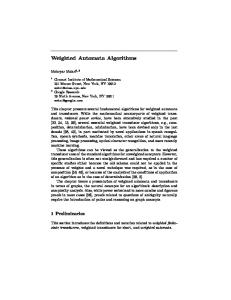
The layered structure of WebTP is shown in Figure 1. Between the application and the transport layer is the socket interface, resembling the Berkeley Socket Interface. The transport layer is divided into Flow Management (FM) Layer, where connections and ADUs are managed. The functions of the FM layer includes • connection setup, teardown and management • pipe setup, teardown and management • ADU management, which includes accepting ADUs from the application for transmission, receiving ADUs from the network layer and delivering of the ADUs to the application, segmentation of ADUs into packets and re-assembly of packets into ADUs, and managing reliability of ADUs.
Application Socket Interface Flow Management Network Control Measurement
Congestion Manager
Scheduler
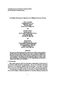
Figure 1: WebTP layered structure Here we refer the duplex communication channel between a pair of IP end-hosts as a pipe. A connection, on the other hand, terminates its two endpoints at the application level. Multiple connections can be multiplexed into a single pipe. Figure 2 illustrates the relationship between a pipe and connections. The connection in WebTP is a lightweight structure whose purpose 7
is to provide the application with a simple logical view of the communication channel. A pipe establishes the actual end-to-end path in the network, probes the available bandwidth on the path, and participates in congestion control. Host 1 Application 1
Host 2
Application 2
Application 2
Application 1
Connections
Pipe
Figure 2: Relationships of applications, connections and pipe The layer below the FM layer is the Network Control (NC) layer, which has a Congestion Manager module, a Scheduler module and a Measurement module. The Measurement module is responsible for monitoring the congestion situation of the network path, i.e. the pipe, as well as for measuring the rate and other statistics of the network path that are relevant for the control algorithms. This module also measures the bandwidth usage by the outgoing or incoming traffic of each connection. The pipe-level congestion manager can exploit the regularity in the traffic statistics measured across all connections in a pipe. The Scheduler module performs rate allocation for the connections by scheduling transmission of packets from each connection. It should respect the ADU boundaries in that it always tries to complete transmission of an ADU before starting transmission of a new ADU. The main challenge in the transport design is to manage the complexity due to the required fine-grained control of reliability, connection scheduling and integrated management of congestion for the pipe. The transport needs to manage the ADUs, connections, and pipes.
2.2
Application-Level Framing
One of the objectives of WebTP is to provide support for arranging transmission orders of objects in a web page. An application-level object is represented by a WebTP ADU. Since the meanings of objects are application-specific, the framing of ADUs is done at the application level. For the same reason, the application should be responsible for scheduling the ADU transmissions, including ordering and dynamically re-ordering ADUs, changing an ADU’s reliability requirement, and canceling the transmission of an ADU. The application should buffer ADUs and only send them to the transport layer when they can be transmitted immediately. Since we expect very few ADUs buffered at the sender side of the transport layer, the transport does not support re-ordering of ADUs or canceling of ADUs. The transport level should be aware of the ADU boundaries so that it can deliver data to the applications based on the ADU boundaries. ADUs are segmented into transport packets before they are sent to the network layer. At the receiver-side transport, packets are re-assembled into ADUs before they are delivered to applications. 8
2.3
Connection and Pipe Management Services
A set of application programming interface (API) is needed so that the application and the transport can communicate service requirements, their fulfillment status and network conditions. The services provided by the WebTP transport layer can be classified into connection and pipe management services, quality management services, data management services, and network monitoring services. WebTP provides connection-oriented services. Under the normal mode of WebTP, a connection is established before applications on two hosts can transfer any data. Unlike the connection in TCP, the connection in WebTP is a lightweight object whose primary purpose is to provide the application with a handle on a transparent communication channel. Most of the network control functions are delegated to a different object, the pipe. A pipe is an abstraction of the network path between two IP hosts, possibly shared by many connections. The distinction between the connections and the pipe reflects the view on the partition of the transport into application-support functions and network functions. We will show later that, as one of the benefits of this partition, network functions can be integrated across connections. Another advantage of having both the connections and the pipe is that the application can freely use connections without worrying about performance hit from heavy protocol processing associated with network control. For instance, the application can open a connection for each object request. The transport provides interfaces for connection setup and close, status report of connections and the pipe, and change of status. 2.3.1
Connection and Pipe Setup
When an application wants to communicate with remote hosts, it first opens a socket with the UNIX-style socket() and bind() calls [24]. socket(domain, type, protocol, flags); int s, domain, type, protocol; error = bind(s, addr, addrlen); int error, s, addrlen; struct sockaddr *addr; where WebTP is among the choices for the protocol parameter. We add a type called SOCK ADU for which WebTP is the default protocol. The precise meaning of this socket type is explained later. The parameter flags is used only when the protocol is WebTP. It is derived from the following constants. FAST 0x01 INTERACTIVE 0x02 BULK 0x04 REALTIME STREAM 0x08 BUFFERED STREAM 0x10 SHARED PIPE 0x20 DEDICATED PIPE 0x40 FAST indicates that fast WebTP option is requested. Each of the next four constants refers to one of the traffic classes. The constants ending with PIPE are the types of pipes
9
requested. DEDICATED PIPE means that the connection does not share pipe with other connections. A new pipe should be opened for the connection. SHARED PIPE means the connection can share a pipe with other connections. At this moment, we assume that all pipes are of the SHARED PIPE type for simplicity. Only one of the traffic classes and one of the pipe types should be selected for each socket. The client application which initiates a connection uses the connect() call. error = connect(s, serveraddr, serveraddrlen); int error, s, serveraddrlen; struct sockaddr *serveraddr; The server uses listen() and accept() calls to wait and accept client’s connection-setup requests. error = listen(s, backlog); int error, s, backlog; snew = accept(s, clientaddr, clientaddrlen); int snew, s, clientaddrlen; struct sockaddr *clientaddr; When executing connect() with the SHARED PIPE socket type, the transport first checks if the FAST flag is specified. If FAST is not selected, the transport looks for a shared pipe associated with the destination IP address of the connection. If such a pipe does not exist, the transport calls an openpipe() function and creates a pipe data structure. The connection data structure and the pipe data structure are linked together. Then, the protocol sends a SYN packet to the destination host, trying to establish the pipe and the connection. Three-way handshake is necessary for establishing a pipe in this case. When the transport returns from connect(), either both the pipe and the connection are established, or a “connection time out” error message is returned when the connection can not be established. At the server side, listen() calls a pipelisten() routine, which is ready to receive SYN packets. At this point, listen() returns. When the application calls accept(), the transport calls pipeaccept() routine to establish the pipe data structure. A new socket descriptor is generated and linked with the newly created pipe structure. If the application calls accept() again in the future, the transport will return a new socket without calling pipeaccept(). In the case when a shared pipe already exists, connect() also sends a SYN packet and can immediately returns. No new pipe is created. When receiving the SYN packet, the server creates a new connection and associates it with an existing pipe. The server acknowledges the SYN packet with a SYN+ACK packet. The SYN packet in this case is automatically a reliable packet. The transport is responsible for its successful transmission. The client can immediately send or receive data after connect() returns. The server can immediately send data after the SYN packet is received. Since the data packet can arrive at the receiver before the SYN packet, the reception of the first data packet or SYN packet, whichever arrives first, triggers the creation of a new socket. If connection setup fails, the received data will be dropped by the transport. Notice that when a pipe exists, WebTP speeds up connection setup by eliminating the three-way handshake and by send data packets concurrently with the SYN packet used for connection setup. If a pipe doesn’t exist, the Fast WebTP option can also speed up connection 10
setup. 2.3.2
Fast WebTP
If the FAST flag is selected with the socket() call, the application indicates its desire for a fast connection startup, which can improve the responsiveness of interactive applications. This can be especially beneficial in the case of browsing web pages that require many downloads from many servers. One source of improvement comes from the reduction of the time taken by the three-way handshake in establishing a pipe. Another source comes from less stringent congestion control. Fast WebTP is capable of emulating connectionless services. In Fast WebTP, before the completion of three-way handshake, the transport of the sender side can start transmitting. When the receiver side receives data before the completion of three-way handshake, the transport can set up the socket and deliver data to the application. The application decides whether to accept or reject the data. If the pipe setup fails, the transport at the receiver side needs to notify the application, and the application closes the socket. At the client side, connect() call sends a SYN packet and immediately returns. The application can start to sending or receiving data. Simultaneously, the transport tries to set up the connection, and the pipe if necessary. When the client issues send() immediately after the connect() call. The data packet will use the sequence number picked by the transport layer. We next examine the details of different situations. When there already exists a pipe before the connect() call, everything is the same as the regular WebTP with an active pipe. The situation is far more complicated when the pipe does not exist. The connect() call creates a socket, sends a SYN packet then returns. At this point, the client can start sending or receiving data packets. Suppose the client sends data. It is possible that the data packets arrive at the destination before the SYN packet. First, if the server application specifies that it is unwilling to use Fast WebTP, i.e., it uses regular WebTP, the early data packets are temporarily buffered, waiting for the completion of pipe and connection setup. If the server application is willing to use Fast WebTP, the first packet (either data or SYN packet) that arrived at the server initializes pipe data structure and appends a connection to the connection queue. The server can now accept() the connection. Properly assembled data can be delivered to the application by allowing recv() to return. Data read by the application before the completion of the three-way handshake has its FAS bit set. The application is required to issue a rejectdata() call to indicates whether it accepts or rejects the data. Data can be rejected for many reasons, such as security concerns. When this happens, the receiver-side transport rejects all data received before the completion of the threeway handshake, and buffers them until three-way handshake completes. After the three-way handshake, the connection is again appended to the connection queue, waiting to be accepted. The application can now accept() the connection again and receive data packets by recv(). If the data with FAS bit marked is accepted, it is still possible that the transport later decides not to setup the pipe and the connection. Possible reasons are that the three-way handshake cannot be completed, or that the SYN packet has never been received. The transport issues an upcall to the application about such a decision so that the application can take actions such as rolling back the received data and/or terminating the process/thread that is receiving on that connection. The application is also responsible for closing the socket that will not be used again. Data packets buffered at the transport layer will be dropped. The transport at the client 11
side will simply time out the connection and notifies the application. Before the setup of the pipe is completed, the server can also send data to the client. The treatment of data with FAS bit set is the same at both client and the server side. The basic rule for acknowledgment is that the transport does not acknowledge any data packets until the application indicates its acceptance of the packets through rejectdata() call and until the three-way handshake has completed. The SYN packet does not contain data and is always reliable. The transport is responsible for retransmission of lost SYN packet. The packets, including the SYN packet, transferred before the proper establishment of the pipe are not congestion controlled. It is required that no more than n packets are allowed to be transmitted in this fashion, where n is a small number, such as 4. The parameter n is somewhat equivalent to an increased initial congestion-window size. The bandwidth measurement and estimation algorithm can help to determine n adaptively. Fast WebTP is designed so that some applications can avoid one round trip time (RTT) for setting up the pipe using the three-way handshake. It is suitable for applications with stringent requirement for responsiveness. Three-way handshake is originally designed to prevent data from terminated connections from being accepted. In Fast WebTP, after three-way handshake is completed, the transport might discover that the accepted data are from terminated connections. Hence, Fast WebTP is useful either when receiving the erroneous data does not matter or when the application has the ability to roll back and replace the erroneous data with new data. Web browsing presents a special case for the former situation. Imagine the client makes a GET request of web page. The GET message is sent to the server while three-way handshake is underway concurrently. The server temporarily accepts the connection. It verifies that the GET message does not lead to security breaches and replies with the html file when the transport is in the second step of the three-way handshake. The replied html file and the SYN+ACK are very likely to arrive at the client in close proximity in time. From the client’s point of view, it is only necessary to complete the second step of the handshake before it can accept data with confidence. Therefore, it is likely for the client to save one round-trip time. Notice that if the pipes are available most of the time, which happens when there is a large degree of connection/traffic aggregation, the regular WebTP already improves the connection setup times over TCP. In that case, the gain from the Fast WebTP over the regular WebTP is not significant. It is when the pipe is unavailable that Fast WebTP improves the connection setup time over both the regular WebTP and TCP. 2.3.3
Connection and Pipe Classes
WebTP supports four classes of connections, corresponding to short interactive flow (INTERACTIVE), bulk file transfer (BULK), real-time stream (REALTIME STREAM) and buffered stream (BUFFERED STREAM). The connection class is specified by the flags parameter of the socket() call. The class information is used by the protocol to assign connections to pipes and to customize scheduling and congestion management. For example, the pipe scheduler can determine to use a class-based scheduling algorithm. The congestion manager may take less stringent approach of enforcing congestion control for short interactive traffic when the additional traffic constitutes a small portion of the measured network capacity. Each pipe has two attributes. The first attribute indicates if it is a shared pipe or a 12
Connection Classes
Pipe Classes (For Shared Pipe)
INTERACTIVE BULK REALTIME STREAM BUFFERED STREAM
BULK BULK BULK BULK
PIPE PIPE PIPE PIPE
Table 1: Connection to Pipe Mapping: Example 1 Connection Classes
Pipe Classes (For Shared Pipe)
INTERACTIVE BULK REALTIME STREAM BUFFERED STREAM
BULK PIPE BULK PIPE REALTIME PIPE BULK PIPE
Table 2: Connection to Pipe Mapping: Example 2 dedicated pipe. This attributed is specified by the flags parameter of the socket() call. At the connection setup, if the SHARED PIPE flag in the socket() call is selected, the connection is associated with a shared pipe; if the DEDICATED PIPE flag is selected, the connection is associated with a dedicated pipe. The second attribute of the pipe indicates the class type of the pipe, which takes a value from among BULK PIPE, BUFFERED STREAM PIPE, REALTIME PIPE and INTERACTIVE PIPE. A dedicated pipe contains one and only one connection. It opens and closes with the connection, and inherits the class type from the connection. Since traffic can not be aggregated across connections when dedicated pipe is used, we expect rare use of this pipe class. The degree of traffic aggregation allowed by a shared pipe depends on the mapping from connection classes to pipe classes. The following are three examples of a mapping, which can be configured statically. The class-mapping table allows the flexibility of adapting the protocol to the physical network. For instance, if the underlying physical network can not differentiate different classes of traffic, then the mapping in example 1 (Table 1) allows the most traffic aggregation. If the network distinguishes real-time traffic from non-real-time traffic, the mapping in example 2 (Table 2) is the most appropriate. Because of service differentiation at the router and switches, real-time traffic and non-real-time traffic see different network conditions even if they travel through exactly the same network path. The bandwidth available to the real-time traffic and Connection Classes
Pipe Classes (For Shared Pipe)
INTERACTIVE BULK REALTIME STREAM BUFFERED STREAM
INTERACTIVE PIPE BULK PIPE REALTIME PIPE BUFFERED STREAM PIPE
Table 3: Connection to Pipe Mapping: Example 3
13
the non-real-time traffic might be completely different. Reliability concern also favors this mapping, since lost real-time packets are not retransmitted, but lost non-real-time packets may need to be retransmitted. Furthermore, congestion management of real-time traffic should also be different from non-real-time traffic. If the network distinguishes all four classes of traffic, the mapping in example 3 (Table 3) is the most appropriate. The class mapping should be chosen carefully. Suppose the network does not differentiate real-time and non-real-time traffic, the separation of real-time and non-real-time traffic at the pipe level leads to a smaller degree of traffic sharing and integrated management. The definition of different pipe classes gives WebTP the flexibility to incorporate future advances for QOS support at the network layer. 2.3.4
Connection and Pipe Close
WebTP uses the socket-style close() and shutdown() for terminating connections, both of which have the similar meaning as in the Berkeley Socket Interface [24]. Closing a connection will not automatically close a pipe. When a pipe has been idle for some fixed amount of time, or when the resource for creating new pipes runs low, the transport is responsible for closing a pipe by sending a packet with the PFI bit set. WebTP uses a similar set of states to those in TCP for controlling the connection and pipe, except that the set of states are split between the connection and the pipe.
2.4 2.4.1
Quality Management Services Bandwidth Allocations Provisions
WebTP has a set of APIs that allow the application to specify the bandwidth when a connection is opened and to adjust it during the lifetime of the connection. The application can also query the bandwidth of connections that belong to the same user. A bandwidth control application can take advantage of these provisions and control the rate assignment for a set of connections of the same user. The set of APIs are: int getsockopt(int s, int level, int optname, void *optval, int optlen); int setsockopt(int s, int level, int optname, void *optval, int optlen); int getallsockets(int id, int *s, int slen); Getsockopt() and setsockopt(), which are borrowed from the BSD operating system [24], manipulate the options associated with a socket. Options may exist at multiple protocol levels; they are always present at the uppermost “socket” level. When manipulating socket options, the level at which the option resides and the name of the option must be specified. To manipulate options at the socket level, level is specified as SOL SOCKET. To manipulate options at any other level, the protocol number of the appropriate protocol controlling the option is supplied. For example, to indicate that an option is to be interpreted by the WebTP protocol, level should be set to the protocol number of WebTP, which is 100. In the case of WebTP, we define options together with their meanings in Table 4. All options are for the sending side of the connection. Getallsockets() asks the operating system to return all sockets owned by a user denoted by id. With these APIs, a control application can manipulate the rate on behalf the user at the granularity of connection, connection class, or application. The final rate allocation depends on 14
optname
optval type
optval
TRAFFIC CLASS = 0
char*
AVAILABLE RATE = 1
float*
CURRENT RATE = 2
float*
RTT = 3
float*
LOSS RATIO = 4
float*
LOSS BURSTINESS = 5
float*
Name of the traffic class. The scheduling of WebTP outgoing traffic depends on the traffic class. Currently four classes are defined: “INTERACTIVE”, “BULK”, “REALTIME STREAM”, and “BUFFERED STREAM”. The administrator of host defines different traffic classes and corresponding policies for bandwidth allocation. All available traffic class names are listed in /etc/webtp classes. Only valid for getsockopt(). Available rate in bits per second. This is essentially the rate available from the pipe. Available rate in bits per second. Getsockopt() returns the current sending rate of the connection. If the application wants to specify a constant rate at which it wishes to send, it can call setsockopt(). If such a rate cannot be guaranteed by the scheduler, setsockopt() will fail. Only valid for getsockopt(). Round-trip time, measured in microseconds. Packet loss ratio for this connection in the past n RTT Average number of consecutive packets lost in a burst for the connection.
Table 4: Socket Options the requested rates of the current user and competing users, as well as the scheduling policy at the server and network routers. Congestion control can also interfere with the rate allocation on a shorter time scales. The net effect of all these factors is a subject of further study. Notice that when the total specified rate is unsustainable at a scheduler, rates will be interpreted as weights for a weighted fair-queueing scheduler. Another subtle point is that a connection is considered full-duplex only to the extent of connection setup. A connection can have different rate specifications for its two directions. However, since the rate information for each connection is only kept at the sending host, no difficulty arises from this ambiguity. In a typical application, a client application makes a request to set up a connection with the server. The client’s application-level request message contains a rate requirement for the connection in the direction from the server to the client. The server application interprets the rate information and makes a setsockopt() call to set the new rate.
15
2.4.2
Loss Monitoring
The two loss-related options in Table 4 are used only with Getsockopt(). The LOSS RATIO is measured over the last n round-trip-time, where the parameter n is to be determined adaptively. Real-time application can take advantage of this provision to adapt to the network conditions. An admission control application can also rely on it to make admission decision. LOSS BURSTINESS is the average size of loss-bursts. Different loss-burst sizes may indicate different causes of losses. For instance, a large loss-burst may be caused by an unreliable wireless link rather than by congestion, and should be coped with correspondingly.
2.5 2.5.1
ADU Management Services Supported Reliability Requirements
WebTP supports ADU-level reliability, which is the main reason why the transport should be aware of and respect ADU boundaries. When the application makes a request for transmission of ADUs, the sender-side application specifies whether each ADU is reliable or unreliable. A reliable ADU should be delivered without an error by the transport. This necessarily involves retransmission of lost packets for the ADU. Lost packets for an unreliable ADU are not retransmitted. At the receiver side, if all packets of an unreliable ADU are received correctly, they are assembled into the ADU and delivered to the application. If the receiver decides that some packets of the unreliable ADU are lost, the complete ADU is dropped and the transport notifies the application that some unreliable ADU is dropped. Since a single packet loss triggers the dropping of the entire unreliable ADU, the application should be aware of this fact and tries to size the ADUs so that each will fit into one or a few transport packets. Note that the size of unreliable ADUs is limited by the size of the re-assembly buffer at the receiver side. This is not the case for reliable ADU, since the transport can deliver partial ADUs to the application. WebTP guarantees that no more than one copy of each ADU is delivered to the receiver by detecting and dropping duplicated packets. WebTP also guards against late packets from earlier terminated connections through three-way handshake. Fast WebTP provides this feature after the completion of three-way handshake. It has a brief vulnerable period before the completion of three-way handshake. WebTP does not provide transport-level guarantee of in-order delivery of ADUs within the same connection. The decision is based on the assumption that the ordering relationship of data is encapsulated within each ADU and very often ordering among ADUs is not required. We gain the benefit that ADUs can be delivered to the application quickly at the receiver side. At the transport layer, an incomplete ADU does not block other completed ADUs from being delivered. This also makes it easy for the transport to transfer expedite ADUs out of order. When sequencing of ADUs is necessary, it is done at the application level with the help of library functions and the ADU number. The sequencing of ADUs is typically a simple task since the application does not have to worry about retransmission of packets. 2.5.2
Sending and Receiving Data at the Application
Blocks of data are sent through the socket interface via UNIX style send() and recv() calls. No more than one ADU is sent or received each time.
16
int send(int sockfd, char *databuff, char *header); int recv(int sockfd, char *databuff, char *header); where databuff is the starting address of the data portion of the ADU and header is the ADU header. Since the size of ADUs varies and the header length is fixed, the header and the data portion are kept in different data structures. Each send() or recv() call can pass a complete ADU or a partial ADU. The ADU header structure is defined as follows: struct ADU_header { int name; int segnum; int datalen; int option; }; The application is responsible for choosing unique names for ADUs within each connection. The ADU name is needed mainly because we allow the passing of partial ADUs across the socket interface, which can be interrupted by other partial or complete ADUs for two reasons. First, after sending a partial ADU and before its completion, the application may decide to reorder the unsent ADUs. When it does send() again, the application can send a different ADU. Second, the ADUs can arrive at the receiving side out of order, and hence can be delivered to the application out of order. The ADU name is also inserted into the transport packet header so that the receiver can identify all packets that belong to the same ADU for ADU re-assembly. It can also be used by the application for application-specific processing. For instance, integer ADU names may indicate the order of ADUs. With four bytes, it can also convey limited semantic information that is meaningful to the application. The application may handle ADUs differently based on their names. Note that if an application uses complex naming scheme that assigns long string names, it can do so by defining application-specific ADU frames. The standard ADU header will be added to each of these frames. Segnum is the segment number, which is the initial byte number of the current ADU segment in the complete ADU. For example, if the current ADU is a complete ADU or the first segment of an ADU, segnum is 1. Datalen is the length of the ADU data portion. Option is the derived from the following constants. Constants
Hex Values
Semantics
ADU ADU ADU ADU
0x01 0x02 0x04 0x08
the end of an ADU ADU is reliable ADU has urgent priority Used in recv() only. ADU received before the completion of three-way handshake in Fast WebTP.
END RELIABLE URGENT FAST
To provide support for dynamic ADU rendering at the application level, the transport layer should buffer minimum amount of user data subject to the consideration of system call 17
overhead. The actual buffer size may depend on the transmission rate for that connection, and depend on all connections sharing the same pipe. By default, the send() call is non-blocking. The return value of send() indicates how much data has been sent, and serves as a backpressure from the transport to the application. The application can then evaluate the situation and choose appropriate strategy for sending data. For instance, it can scan through the buffered data at the application layer and manipulate them based on its need. When sending data, the application should determine the frequency of send() calls based on a number of considerations. For instance, delay sensitive data warrants the application to call send() frequently. In other cases, the application can chose a large chunk of data to send in order to reduce the frequency of the send() system call. An appropriate scheme should balance three things. The transport should not be idling when bandwidth is available in the transmission path. The application keeps most unsent data for dynamical rendering. The number of system calls should be kept at a level that does not overburden the CPU. When receiving data from the transport, the application calls recv(). The recv() call is blocking by default. The transport fills the receiving buffer up to the requested amount of data, and returns. The transport tries to return as quickly as possible subject to the consideration of system call overhead. The application also needs an API to reject any received ADUs with FAS bit set, i.e., those ADUs that arrive before the proper set up of the connection and the pipe in Fast WebTP. This is done with the rejectdata() call. int rejectdata(int sockfd, int nam, int t); where name is the ADU name and t is a flag. If t = 0, the ADU has been accepted by the application. Otherwise, it has been rejected. 2.5.3
Supported ADU Priority Levels
WebTP supports two priority levels at the granularity of an ADU: the urgent priority and the normal priority. The urgent priority ADU is given scheduling priority for transmission at the sender, and is delivered to the application with minimum delay at the receiver side. Since supporting urgent ADU put more stress on the processor (e.g. due to context switching) and can negatively affect other ADUs, it is recommended that urgent priority is used infrequently and is applied only to ADUs of small sizes. Infrequent measurement and/or control ADUs are examples that may use the urgent-priority service. The ADU priority information is encoded in the ADU header.
2.6 2.6.1
ADU and Packet Formats ADU Framing
Complex ADU framing should be left to the application, as the name Application Level Framing (ALF) implies, possibly with the help of libraries for different types of ADU frames. For example, a video or audio frame may look like RTP frames. However, the ADU frames should have a common part so that ADUs can be passed across the socket interface. In our design, the ADU header assumes this role.
18
2.6.2
Packet Format
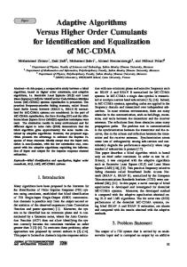
0 1 2 3 0 1 2 3 4 5 6 7 8 9 0 1 2 3 4 5 6 7 8 9 0 1 2 3 4 5 6 7 8 9 0 1 +-+-+-+-+-+-+-+-+-+-+-+-+-+-+-+-+-+-+-+-+-+-+-+-+-+-+-+-+-+-+-+-+ | Packet Number | +-+-+-+-+-+-+-+-+-+-+-+-+-+-+-+-+-+-+-+-+-+-+-+-+-+-+-+-+-+-+-+-+ | Acknowledgment Number | +-+-+-+-+-+-+-+-+-+-+-+-+-+-+-+-+-+-+-+-+-+-+-+-+-+-+-+-+-+-+-+-+ | Acknowledged Amount | +-+-+-+-+-+-+-+-+-+-+-+-+-+-+-+-+-+-+-+-+-+-+-+-+-+-+-+-+-+-+-+-+ | ADU Name | +-+-+-+-+-+-+-+-+-+-+-+-+-+-+-+-+-+-+-+-+-+-+-+-+-+-+-+-+-+-+-+-+ | Segment Number | +-+-+-+-+-+-+-+-+-+-+-+-+-+-+-+-+-+-+-+-+-+-+-+-+-+-+-+-+-+-+-+-+ | |U|A|R|S|F|R|E|F| | Source Port |R|C|S|Y|I|E|N|A| | |G|K|T|N|N|L|D|S| +-+-+-+-+-+-+-+-+-+-+-+-+-+-+-+-+-+-+-+-+-+-+-+-+-+-+-+-+-+-+-+-+ | | C | P |P|P| | | Destination Port | C | C |T|F|RES| | | L | L |Y|I| | +-+-+-+-+-+-+-+-+-+-+-+-+-+-+-+-+-+-+-+-+-+-+-+-+-+-+-+-+-+-+-+-+ | Data | | | | Offset| RES | Window | | | | | +-+-+-+-+-+-+-+-+-+-+-+-+-+-+-+-+-+-+-+-+-+-+-+-+-+-+-+-+-+-+-+-+ | Checksum | Options | +-+-+-+-+-+-+-+-+-+-+-+-+-+-+-+-+-+-+-+-+-+-+-+-+-+-+-+-+-+-+-+-+ | Options | Padding | +-+-+-+-+-+-+-+-+-+-+-+-+-+-+-+-+-+-+-+-+-+-+-+-+-+-+-+-+-+-+-+-+ | data | +-+-+-+-+-+-+-+-+-+-+-+-+-+-+-+-+-+-+-+-+-+-+-+-+-+-+-+-+-+-+-+-+ Figure 3: WebTP Packet Header Format
The WebTP transport packet format is shown in figure 3. The first three header fields are used by the Congestion Manager for congestion control and loss detection. The rest of the fields are used mostly in the FM layer. Their meanings are as follows.
19
The sequence number of the packet, which is the first byte of data contained in the packet. The sequence number is shared by all connections for the pipe. Acknowledgement Number The sequence number for the next packet expected. Acknowledgement Amount The number of bytes acknowledged ADU Name The name picked by the application for the ADU; the same as the name field contained in the ADU header Segment Number The index number for the first data byte of the packet within the same ADU; the same as the segnum field contained in the ADU header A value 1 for the control bits has the following meanings. URG (Urgent) This is an urgent packet. ACK (Acknowledgement) This packet carries acknowledgement information. RST Abort the connection. SYN (Synchronizaton) This is a synchronization packet for setting up a connection and/or a pipe. FIN This is the last packet of the connection. Close the connection REL (Reliability) This is a reliable packet. END (End) This is the last packet of the ADU. FAS (FAST WebTP) The packet is sent before the completion of three-way handshake. PFI Close the shared pipe. (Note that dedicated pipe is non-persistent and closes when the connection closes.) CCL and PCL denote connection and pipe classes, respectively. 00 Short interactive traffic 01 Bulk file transfer 10 Real-time stream 01 Non-real-time stream (buffered stream) PTY denotes the pipe type. 1 shared pipe 0 dedicated pipe In Fast WebTP, all data packets transmitted before the completion of the three-way handshake have their FAS bits set. The rest of the fields have the same meaning as in TCP [15] Packet number (PN)
2.7
Packetization and Reassembly
Conceptually, the NC layer is a new layer with its own control fields in the header. Packetization is performed in two steps. The fields that are relevant to the connection and ADU are filled at the FM layer. Fields that are relevant to the pipe or that are used for congestion control are filled at the NC layer. The latter include Packet Number , Acknowledgement Number, Acknowledgement Amount , FAS, PCL, PTY, and Window.
20
3
WebTP Algorithms
WebTP introduces some algorithmic challenges. We have already discussed the Fast WebTP algorithm in the protocol section. Other important algorithms are in the areas of congestion control, scheduling, loss detection, network measurement, and bandwidth estimation. In the following, we will discuss a few at various levels of details.
3.1
Data Services
The FM layer maintains four ADU queues for each connection: the sending queue with urgent priority, sending queue with normal priority, the receiving queue with urgent priority and the receiving queue with normal priority. Each queue is a link list of ADU control blocks. A data block can be a partial ADU instead of a complete ADU. The data block is cleared from memory, - at the sender side, for a reliable ADU, after the data block is completed sent and acknowledged. - at the sender side, for an unreliable ADU, after it is completely sent or after it is partially sent and some packets from the ADU have been lost. - at the receiver side, for a reliable ADU, after it is delivered to the application. (In Fast WebTP, also after the application has accepted it through rejectdata() call.) - at the receiver side, for an unreliable ADU, after it is delivered to the application, or one or more packets have been lost. (In Fast WebTP, also after the application has accepted it through rejectdata() call.) The control block is cleared after the complete ADU data block is cleared from the memory. Urgent ADUs take precedence over normal ADUs for transmission or delivery. The Packet Number (PN) is a shared addressing space by all connections sharing the same pipe. Acknowledgement is based on PN. Demultiplexing of packets at the receiver and reliability handling both use PN in conjunction with locally stored data structures. Here is how it works. 3.1.1
Sender Side
The Congestion Manager (CM) of the sender sends packets sequentially. The receiver acknowledges all received packets. The sender can then detect packet losses in a way very similar to TCP loss detection, i.e., based on timeout and on duplicated acknowledgement packets. At the CM, the sender keeps a mapping between PN and the actual packet so that it knows the ADU and connection associated with the lost packet. Each pipe maintains a list of transmitted packets yet to be acknowledged. When an acknowledgement for a packet comes, that packet is marked as having been acknowledged. This list is checked frequently for the purpose of clearing data blocks. If a loss is inferred for a reliable packet, a retransmission is scheduled immediately. The congestion manager informs the appropriate connection and ADU about the lost packet. If the lost packet is unreliable, the complete ADU is dropped and the application at the sender-side is notified about the loss.
21
3.1.2
Receiver Side
When a packet is received, the CM sends appropriate acknowledgment packet back to the sender. Notice that the receiver is capable of detecting packet losses. However, it is difficult to infer to which connection a lost packet belongs. When a packet is received, it is demultiplexed and sent to the connection at the FM layer with minimum delay, where ADU reassembly takes place. For every connection, the urgent ADU queue takes priority over the normal ADU queue when the transport returns the recv() call. ADUs should be delivered as soon as possible to improve the perceived response time for interactive applications and to secure the delay bound for real-time media delivery. The transport also needs to balance the system call overhead and the timeliness when making a delivery decision. The amount of delay can be traded for efficiency. Although it is desirable to deliver data on ADU boundaries, in practice, there has to be an upper bound on the amount of data that can be accumulated before a delivery when a ADU is large. Hence, both a complete ADU and a partial ADU are eligible for delivery. Within an ADU boundary, the transport is responsible for in-sequence delivery of packets. Thus, a partial ADU can be delivered to the application provided all its previous segments are delivered. The transport makes the decision when to deliver ADUs to the application or when to drop incomplete unreliable ADUs. The ADU name will be taken from the ADU Name field of the packets. Hence, the application can identify each ADU unambiguously. A partial unreliable ADU needs to be timed out if some of its packets are lost.
3.2
Congestion Control
The design of WebTP’s congestion control algorithm has been a centerpiece of the project. In the current Internet, connections are either congestion controlled rigorously with TCP, or uncontrolled with UDP. The former typically applies to elastic data applications and the latter applies to inelastic real-time applications. Clearly, there is some room in between these two extreme control schemes. Because the real-time traffic is typically controlled by its datagenerating mechanism and has stringent delay requirement, the TCP congestion control is not a good choice for it. However, congestion monitoring can still help real-time applications. For instance, adaptive real-time applications can reduce their rates in response to network congestion. Admission control can be implemented to regulate the overall number of real-time connections on the network path. WebTP uses different congestion control schemes for different classes of pipes. Realtime pipes only monitor the network congestion. The packet loss information is passed to the applications. Non-real-time pipes are congestion-controlled by TCP-styled algorithm. New packets are not allowed to be transmitted when the total number of outstanding packets reaches the congestion window size. In the case when a real-time connection is multiplexed into a nonreal-time pipe, the real-time connection will be congestion controlled. This undesirable effect of congestive blocking of real-time traffic can be mitigated by pipe-level scheduling that gives real-time traffic priority. Application-level framing makes it possible for the application to drop outdated real-time packets before they are sent to the transport.
22
3.2.1
Congestion Monitoring for Real-time Pipes
Each real-time pipe monitors the network congestion, but does not block the transmission of packets. (Note that his does not mean that real-time connections are not congestion controlled.) Typically, the transport sends a packet immediately after it is received from the application. The degree of congestion is measured by the packet loss ratio experienced by the real-time pipe. WebTP uses the Packet Number to detect packet losses in ways similar to TCP. Each packet carries with it a sequence number. The receiver acknowledges each received packet by issuing an ACK packet. A packet is declared lost by the sender if (i) it has not been acknowledged when the timer expires, or (ii) when there is a gap in the acknowledgement sequence numbers. The gap is detected with the familiar three-duplicated-acknowledgement scheme used in TCP. That is, the reception of three or more acknowledgements of the same packet indicates a packet loss. We omit the details of the timer algorithm, which resembles the retransmission timer of TCP. Compared with TCP, the complication about the acknowledgement scheme comes from the fact that real-time packets are normally unreliable packets, which will not be retransmitted when they are lost. A cumulative acknowledgement scheme as the one in TCP will fail when an unreliable packet is lost, because the acknowledgement number will never be advanced after that. We will specify a acknowledgement scheme in section 3.4. Loss statistics is passed to the application through loss-related APIs. 3.2.2
Congestion Control of Non-real-time Pipes
For a non-real-time pipe, a congestion window is used to regulate the number of unacknowledged packets. The window size is increased with successful transmission of packets and decreased when a loss is detected. Loss detection is the same as in the congestion monitoring for real-time pipes. WebTP uses past bandwidth information to help the window control algorithm. It also combines the close-looped window-based control with an open-looped rate-based control in an effort to reduce packet losses. We observe that TCP’s congestion control is effective on a short timescale during congestion avoidance. TCP’s window-based control enforces the conservation principle [18] that a packet is not released into the network until another packet has exited the network. This principle has been proven effective in maintaining network stability, but is also somewhat conservative. TCP takes no advantages on the past observations about the available bandwidth. At any moment, the available bandwidth is assumed completely unknown. During congestion avoidance, TCP probes the bandwidth very gradually by allowing no more than one extra packet to be transmitted in one round-trip time than the previous round-trip time. As a result, TCP’s congestion avoidance can be slow in ramping up the window size to the appropriate level. TCP’s congestion avoidance eventually leads to packet loss by increasing the traffic. TCP’s slow-start phase also has a few drawbacks. It starts its window size at one packet, and then increases it exponentially. This behavior can be both too conservative and too aggressive depending on the network situation. It is too conservative since it takes quite a few round-trip times before the window size becomes reasonably large. Interactive application will suffer from the slow opening of the window. It is also too aggressive when the network reaches congestion state. In particular, in an environment with many short interactive connections, the poorly controlled connections can cause frequent packet losses at the router [26]. When the 23
buffer at the routers overflows, many packets can be lost. Consequently, packet loss in TCP can be frequent, as well as expensive due to the lack of a good loss-detection mechanism. More specifically, a few factors contribute to the frequent packet loss in TCP’s congestion control. First, the slow start connections rapidly ramp up their rate and can quickly causes a large number of packet losses. Frequent connection arrival leads to frequent packet losses induced by the slow-start phase. Second, packets can be dropped during the normal operation of congestion avoidance. This source of loss depends crucially on the buffer size at the router. When the buffer size is relatively small, the loss can be significant. It also depends on the number of simultaneous connections. Insufficient buffer space and large number of simultaneous connections can both lead to significant losses. A key drawback of the window-based scheme lies in that it only tells whether a packet is lost or not, and it does not tell what the average sustainable rate is. In WebTP, the ratemonitoring device for the pipe can tell the latter information. It is, therefore, possible to use both the window information and the rate information to better control the traffic. WebTP tries to reduce packet losses and increase the rate ramp-up speed in three ways. First, through pipe sharing, only the very first connection of the pipe needs to start in the slow-start phase. Later connections normally start in congestion avoidance phase. Not only can packet loss ratio be reduced, but connections can also start at a higher rate than they would if they start in the slow-start phase. For the interactive connections, higher starting rate means better response time. Second, WebTP keeps the pipe alive and the available rate information remembered for some time after all connections have ended. The pipe can be reused when a new connection starts. The new connection starts in slow-start phase and changes to congestion avoidance phase as the connection rate exceeds the recorded available rate. The initial window size is tied to the recorded rate. For instance, if the recorded rate is relatively high, the initial window size can be significantly greater than one. Finally, rate is also used in the congestion avoidance phase to further reduce the packet loss ratio. In the normal operation of congestion avoidance, the window size increases until the current rate is near the available rate. After that, the window size stops increasing. Every once in a while, the bandwidth is probed again by increasing the window size until a packet loss is detected. This will invalidate the previous rate measurement and a new measurement is recorded. In short, WebTP reduces the frequency of loss-based bandwidth probing technique. Due to the time-correlation of the network traffic, we expect the rate information should be relevant for an extended period (e.g., many round-trip times). It is also useful to point out that the rate and window size operate on different timescales. Note that since the measured rate is an average quantity over certain time interval, it automatically has some memory of the past. Therefore, it is natural to combine the use of rate and window in network control. The rate information plays a pivotal role in scheduling, as will be discussed later. 3.2.3
Current Rate and Loss Monitoring
The current rate and number of lost packets for each connection and pipe are measured constantly. Within each prescribed measurement interval, three quantities are measured: the number of packet sent, the number of acknowledged packets and the number of lost packets. The traffic rate and the loss ratio are derived from these quantities. Applications can query the packet loss and rate information through the set of rate and loss query APIs for possible 24
bandwidth adaptation and connection admission control. 3.2.4
Available Bandwidth Probing
Rate monitoring discussed in the previous subsection concerns about the actual bandwidth usage. Although the current usage and the currently available bandwidth may coincide, they can frequently diverge from each other. The latter can often be more useful than the former for the purpose of congestion control and scheduling. When the currently available bandwidth is saved, it becomes the recorded or historical available bandwidth. WebTP normally uses the congestion window size to estimate the available rate for non-real-time pipes. In the case when not enough window-size samples are available at the startup of a pipe, WebTP estimates the available bandwidth by an algorithm resembling the packet-pair algorithm [20].
3.3
Scheduling across Connections
The measured available bandwidth for a pipe is allocated to the connections by the pipe scheduler. Each pipe scheduler is an instance of a general scheduler we are developing. The higherlevel goals of designing a general scheduler are to provide mechanisms for implementing a wide range of traffic classification and bandwidth management policies, to encourage traffic aggregation, hence increase bandwidth utilization and to have a structured implementation and programming interfaces. The general scheduler defines a few abstract connection classes. It generalizes the hierarchical packet fair queueing scheduler (HPFQ) [4] in a number of ways. First, HPFQ scheduler has only one connection class whose requirement is specified by its required rate. Our general scheduler defines three connection classes, which are given the abstract names: type-I, type-II and type-III. Type-I connections require rate guarantee at the smallest possible timescale; typeII connections require delay guarantee and are typically real-time or interactive connections; and type-III connections require a rate guarantee on the longer timescale and are typically besteffort traffic. These class definitions make it possible for the scheduler to handle connections and applications with diverse rate and delay requirements. Second, the general scheduler incorporates weighted-fair-queueing and priority-queueing into the bandwidth sharing hierarchy. Third, due to the regular architecture of the scheduler and due to the abstract definition of the connection classes, each instance of the scheduler can be configured with flexibility. In one example, we can map all connections into type-III connections of the scheduler. In another example, we can map the real-time connections into type-II connections and everything else into type-III connections. To summarize the goals of the scheduler, we want the scheduler to support the following services (combined with admission control): bandwidth guarantee at the shortest time scale; various probabilistic delay-guarantees; bandwidth guarantee on longer time scales; and simple priority class when bandwidth is uncertain. We also want a structured representation of the above requirements, and a representation that leads directly to implementation. In our abstract scheduler representation, the timescale on which the bandwidth is measured is explicit. Each type-I class is associated with a number φi , which is the rate assignment for the class with index i. Each type-II class is characterized by a tuple (di , pi , γi ), indicating the requirement that Pr(D ≥ di ) ≤ pi , where D is the queueing delay. Note that di can be infinity, and the corresponding class is named type-II-infinity. The optional γi stands for the average 25
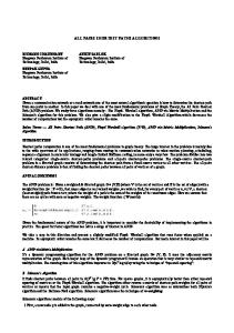
rate of this class, and is used for admission control. Each type-III class is associated with a number ψi , which is the average rate of class i. Next, we define the rules for constructing the scheduling hierarchy. The purpose having a formal procedure is to make the representation of the connection requirements unambiguous, and to lead to a natural and structured implementation of the scheduler. • Type-I class can have type-I, type-II, or type-III as children. • Type-II class has no children, except that type-II-Infinity may have type-III or type-IIInfinity as children. • Type-III class can have type-III or type-II-Infinity as children. • All children of a class must themselves be the same type. Notice that type I can only have type-I as parent. Type-II (not including type-II-infinity) can only have type-I as parent. Type-III can have type-I, type-III, or type-II-Infinity as parent. type-II-Infinity can have type-I, type-III, or type-II-Infinity as parent. As a result of the rules, the bandwidth for all children of a type-I (or type-III) class is defined on comparable timescale. Figure 4 shows a complex instance of the class hierarchy. In the figure, the classes are indexed from the top to bottom, and from left to right, with the root being class 0. Class 1, 2 and 3 require bandwidth guarantee of φ1 , φ2 and φ3 on the shortest possible timescale. Class 4 and 5 also require bandwidth guaranteed of φ4 and φ5 , where φ4 + φ5 = φ1 on the shortest possible timescale. Class 6 and 7 have delay requirements d6 and d7 , respectively. The probabilities of delay being satisfied are p6 and p7 . Class 8 can be delayed for arbitrarily long time. The children of class 8 are class 12 and 13. Each requires a bandwidth ψ12 and ψ13 , respectively, on a long timescale. It must be true that ψ12 and ψ13 sum up to the total bandwidth available to the parent class 8. The relevant time scale here is determined by the timing requirements for the siblings of class 8, since class 6 and 7 will be given higher scheduling priority than class 8. In this example, we also allow class 13 to have type-II-infinity children, and they are class 16, 17, and 18. Since they all have the same delay requirement, some other means must be used to differentiate them in the actual scheduling. In our scheduler implementation, they are given different priorities. We introduce a simple implementation of the scheduler. The immediate children of a class are scheduled as follows: • If the children classes are of Type-I, then PFQ is used. • If they are of type-II, then a priority scheduler is used. Type-II classes are numbered by 1, 2, ..., n, which stand for their scheduling priorities. For instance, a class with a lower delay bound takes priority over one with a higher delay bound. When two type-II classes have the same delay bound, the one with smaller pi value takes priority over the one with larger pi value. Type II-Infinity classes are numbered a priori. • Type-III classes are scheduled according to PFQ among themselves. In figure 4, the numerical labels (i.e., 1, 2, 3) for the type-II classes indicate the scheduling priority. 26
φ2
φ1
� �
��� ��� � � � ����� ��
φ3
type-I type-II type-II-infinity type-III
φ4
φ5
��� ����1������ ��� ��� �����
���� 3�� � �������� ���� ��
(d6 , p6 )(d7 , p7 ) ψ12
�������� 1���� ��� ���� ���� 2���� ��� � � ��
3��
�
������� ����� ��� �� ����� ����� ��� ��� � ���� ���� �� (d9 , p9 ) (d10 , p10 )
ψ14
���������2 ����� ��� ������ ���� ���
ψ13
����� 1��� �� ��� ���2 ��� �� ����� 3��� �� ��������� ����� ��� ���� ���� ���� ��� ��������� ����� ��� � � � ������� � � � ψ15
ψ19
ψ20
ψ21
Figure 4: An example of the scheduler class hierarchy In the framework of HPFQ, the timing requirement for a real-time connection can be satisfied by proper bandwidth allocation. In our framework, real-time connections can achieve their timing requirement by either being mapped to type-I classes or to type-II classes. Since a type-II class can aggregate many connections with the same delay requirement, it can lead to higher link utilization through statistical multiplexing. Therefore, the use of type-II classes is recommended for real-time connections. Type-I classes are still necessary for policy-based bandwidth allocation. For instance, an organization may wish to request a fixed bandwidth for all their connections. Due to the tremendous generality, our scheduler can be used in complex situations such as the central gateway for a corporate or ISP network. The construction of a particular scheduler should be configurable, either statically or dynamically. With respect to WebTP, we propose the following guideline for constructing the scheduler. First, no scheduling is needed for a real-time pipe, since all packets are transmitted on first-come-first-serve basis. In this case, the number of real-time connections should be limited by admission control. Next, consider a non-real-time pipe that can contain real-time connections (as determined by the connectionto-pipe mapping table). Note that a pipe typically has a time-varying bandwidth. The ability that a pipe can handle real-time traffic critically depends on how the bandwidth varies. For instance, if the bandwidth fluctuates between 10 Mbps and 45 Mbps, then the pipe can handle at least as many real-time connections as a pipe with 10 Mbps constant bandwidth. Therefore, if the bandwidth can deliver guaranteed QOS for real-time connections, the root should be a type-I node. Otherwise, the root should be a type-III node. However, real-time and interactive connections can still be given scheduling priority over file-transfer connections. Finally, if a nonreal-time pipe does not handle real-time connections, the root can be either type-I or type-III node. After the decision on the root node, the rest of the tree are configured by the inherent
27
rules for constructing the scheduler tree. The parameters for each node are determined by a combination of the user’s request and administrative policies, with the latter taking precedence. We show two simple cases in figure 5 and figure 6.
����� �� ���������� ���� ����� ��
type-I type-II type-II-infinity type-III
�������� ���� 1��� ���� ���� 2���� ��� ������� ����� ��� ����� ����� ����� ���
�����3���� ������������
Real-time Interactive
Bulk 1
Bulk 2
Buffered_Stream 3
Figure 5: Non-real-time pipe with real-time connections: with type-I root
!�!�!�!�" !!" #�#�#�#�"$ ##"$ $ $
type-I type-II type-II-infinity type-III
%�%�&�%% &�%% 1&%% �'(' (�'' 2(�'' ('' %�&�&�% &�&�% &&% �(�'( (�(�' (�(�' (('
)�)�)�)�* 3)�)�* ))* )�)�** )�** )**
Real-time Interactive
Bulk 1
Bulk 2
Buffered_Stream 3
Figure 6: Non-real-time pipe with real-time connections: with type-III root
3.4
Loss Detection and Selected Acknowledgement
Since a single sequence space is used for both reliable and unreliable packets, loss detection becomes very tricky. In the case of TCP, the receiver performs positive acknowledgement of the received packets. The acknowledgement is also cumulative in that an ACK packet with a particular Acknowledgement Number acknowledges the successful reception of all packets before that number. Since the packet loss probability is strictly less than 1, the lost packet eventually will get through by retransmission. This guarantees that the acknowledgement is not stuck at some packet sequence number. We can not use the same acknowledgement scheme in WebTP without any modification. When an unreliable packet is lost, it will not be retransmitted. Since the receiver never receives a lost unreliable packet, the acknowledgement sequence number can get stuck forever. The fundamental issue is that for reliable traffic, the sequence number is used for both reliability control and for congestion control. The semantic for reliability control is very strict. 28
The transport needs to give hard guarantee that all reliable packets are delivered eventually. For that matter, the sender needs to receive eventual confirmation of delivery for every reliable packet. Furthermore, positive confirmation rather than negative confirmation is necessary here. The sender can not infer that a packet has been delivered successfully based on the absence of negative feedback, since the negative feedback can be lost in the case of unreliable acknowledgement scheme, and can be delayed for unknown amount of time in the case of reliable acknowledgement. On the other hand, positive acknowledgement is built on the conservative assumption that an absence of a positive acknowledgement indicates the loss of the packet. The price to pay for this pessimistic assumption is the unnecessary packet retransmissions that may exacerbate network congestion and the complication that the receiver needs to detect duplicated packets. The semantic for congestion control is more relaxed, and fundamentally based on negative feedback. It can be more relaxed because the consequence of a losing a congestion-notification message is congestion itself, which will trigger more congestion notification messages. It requires negative acknowledgement indicating some packets have not been received. We can take advantage of the fact that the requirement for reliability control is more stringent than that for congestion control and design a control scheme for reliability control first, then add to it congestion control mechanisms. In the case of TCP, the unreliable, cumulative, and positive acknowledgement scheme is sufficient because, first, the scheme eventually confirms delivery of all packets, and second, the congestion indication can be inferred correctly in most situations. The sender guarantees to retransmit packets that are not acknowledged until reception is confirmed, and the receiver guarantees to acknowledge all received packets. Notice that, due to the nature of cumulative acknowledgement, after the reception of a packet, the packet is acknowledged repeatedly until the end of connection. In the case of WebTP, the above scheme can lead to a deadlock because the sender does not guarantee to retransmit all unacknowledged packets. Fundamentally, this is because the unreliable traffic shares the same sequence space with the reliable traffic. Let us now consider simple reliability control schemes first. Suppose the feedback channel is lossless and acknowledgement packets are delivered in order. Then it is enough for the receiver to positively acknowledge every received packet. In the case that the feedback channel is unreliable itself, i.e., it may lose or re-order acknowledgement packets, either the receiver keeps on acknowledging each received packet positively until the end of connection, or it acknowledges positively each received packet until it knows definitely the sender has received the acknowledgement. In other words, forward acknowledgement is also necessary, which leads to a situation similar to three-way handshake. It is clearly undesirable and impractical to introduce forward acknowledgement or to acknowledge each packet separately and repeatedly until the end of connection. We need to seek a solution with some form of cumulative acknowledgement. In our solution, we use separate sequence spaces for reliable and unreliable traffic, with the help of the REL bit in the packet header. Logically, each pipe has two streams of traffic. Reliability control for the reliable traffic is accomplished using the TCP-styled positive and cumulative acknowledgement scheme. Loss detection is similar to that in TCP. In the case of unreliable traffic stream, the sequence number is used purely for loss detec-
29
tion, which is used for congestion control. It can be done in one of the following two schemes. In the first scheme, loss detection is done at the sender and the receiver sends positive acknowledgement for the received packets. The sender detects packet loss by observing the gaps in the acknowledged sequence numbers or by timeout. This scheme is conservative because all lost packets can be detected but it is possible to incorrectly claim a successfully transmitted packet lost. In the second scheme, the receiver detects loss by observing gaps in the sequence numbers of the forward packets and sends negative acknowledgement packet for each lost packet. It is possible that a lost packet is undetected due to the loss of the acknowledgement packet. Since we only try to control congestion, this problem can be somewhat tolerated. Upon detection of a packet loss, the sender does not attempt to retransmit the lost packet, but may use the information to adjust the congestion window size. Since loss detection is imprecise in both schemes, the application can only get approximate loss notification from the transport. The separation of the reliable and unreliable traffic streams has a slight drawback in that congestion monitoring is not completely integrated, since it is not possible to infer the temporal relationship between the two streams. To avoid this situation is the reason we do not choose a naming scheme where each connection has its own sequencing space. For example, the sender may send the following sequence of packets: (1, 2), (1, 3), (0, 2), (1, 4), (1, 5), (1, 6), (1, 7), (0, 3), (0,4), (0,5), where the first entry of each vector indicates reliability and the second entry is the sequence number of the packet. (We assume each packet has one byte of data.) Suppose the unreliable packet (0,2) has been lost. In the case of receiver-based loss detection, the receiver won’t know this until at least one of the unreliable packets from (0, 3) to (0, 5) is received. In sender-based loss detection, the sender won’t know about the packet loss until at least one packet from (0, 3) to (0, 5) is acknowledged or the timer for packet (0, 2) expires. The sender-side loss detection can potentially take advantage of both packet streams for fast loss detection if it remembers the sending sequence of all packets. In essence, that design partially separates the sequence space for reliability control and congestion control. The congestion control sequence is derived from both the packet sequence number in the packet header and locally maintained records. The acknowledgement for reliability is strictly cumulative, whereas the feedback for congestion control can at most be partially cumulative. Although this scheme works, it requires more processing and more data structure to detect the out of sequence events at the sender. This does not solve the problem that the receiver knows the loss later than it could have been. Notice that the receiver needs to detect packet loss in order to drop incomplete unreliable ADUs. WebTP uses positive and partially cumulative acknowledgement for loss detection of the unreliable traffic. Consider a scheme where the receiver acknowledges every received packet separately, and the sender detects packet losses by observing gaps in the acknowledgement sequence numbers or by timeout. The unreliable nature of the feedback path introduces some problems. First, lost ACK packets induce unnecessary traffic load on the forward path. More significantly, since packet loss triggers reduction in the congestion window size, spurious loss declaration can decrease the throughput of the pipe. Finally, the ACK packets also constitute a significant amount of traffic on the reverse path. Partially cumulative acknowledgement can help to solve these problems. Each ACK packet acknowledges all packets received contiguously, up to the most recently received packet. Since unreliable packets in WebTP are not retransmitted, the received packet sequence will have gaps. The acknowledgement scheme proposed
30
here can handle the situation. For example, suppose the most recently received packet is packet 100. Packet 50 has never been received. Packets 51 to 99 have all been received. The next ACK packet acknowledges packets 51 to packet 100. This scheme resembles cumulative acknowledgement scheme, with possible gaps in the acknowledged sequence. It can help to reduce the reverse path traffic by acknowledging many packets together. Since with high probability the same received packet is acknowledged many times, ACK packet loss in the reverse direction introduces very little spurious retransmission.
4 4.1
Discussions and Conclusions QOS Provisioning
Being able to provide QOS guarantee has been the holy grail of data networking. We have seen different schools of thoughts about QOS provisioning during the short history of data networking. In the research of of ATM networks, QOS requirement is communicated hop-by-hop before the establishment of a connection via a signaling protocol and is provided by algorithms running in the network switches. Signaling protocol is complex, requires standardization and slows down the connection setup. At that time, the Internet had few ATM switches. As researchers were trying to iron out the complexity of ATM technologies, the Internet became increasingly non-ATM. The Internet protocols, such as TCP/IP, did not provide differentiated services. Perhaps partially because of their simplicity, they quietly took over the Internet. As the public are drawn by the Internet frenzy and as the market force extends its reach in the Internet, it has becomes obvious that QOS provisioning should be a necessary part of the network service. The most prominent recent proposal in this area is the Differentiated Services (diffserv) architecture from the IETF [9]. In that proposal, differentiated services are provided by the network layer and by the routers. By diffserv’s view, the Internet is segmented into many Differentiated Services domains (DS domains), each of which normally corresponds to one or more networks under the same administration. Examples of a DS domain include a corporate intranet or an ISP [9]. With the segmentation, differentiated services are provided in a hierarchical fashion. At the first level, each DS domain negotiates a service contract (the so-called Service Level Agreement or SLA) with its customer, which can be a user/user organization or another DS domain. At the second level, each router within a DS domain applies different packet-forwarding behavior (the so-called per-hop-behavior or PHB) to different traffic classes. The traffic class (in diffserv terminology, DS behavior aggregate) is denoted by the DS codepoint carried by the IP packet. The DS codepoint can be changed as the packet passes across DS domain boundaries. Diffserv’s QOS provisioning is more static than that provided by the ATM. The SLA between the customer and the DS domain is expected to remain unchanged for a long time. Since the SLA can be statically negotiated among the relatively few DS domains, there is no need for hop-by-hop signaling to set up each connection. However, diffserv does not specify algorithms that can carry out the SLA at a DS domain. Nor has the research community discovered efficient algorithms that fulfill the SLAs when the network resources permit. In practice, the network providers might try to solve the problem by over-provisioning of the network capacity. To summarize, diffserv is a segment-by-segment and layer-3 solution to the QOS problem. Due to the limitation on the size of the codepoint, service differentiation is 31
applied to traffic classes instead of to each individual connection. Since diffserv requires a large number of network devices to be DS-capable before it can deliver differentiated services, we expect it to have a slow deployment process. WebTP is an end-to-end and layer-4 approach that provides differentiated services to individual connections. End-to-end and layer-4 approach to network control has been the original philosophy of the TCP/IP protocol. If we view the Internet as an opaque cloud, it is natural to wonder what we can infer about the state of the network by observing the input and output traffic. WebTP relies on the idea that much can be inferred based on the network measurement. Each WebTP pipe grabs some bandwidth through its congestion control algorithm over an endto-end network path. The pipe bandwidth is then allocated among connections according to a combination of the scheduling policy and user requirements. WebTP’s approach has several advantages. The application’s service requests can be directly accepted and dynamically adjusted as the user observes the service quality. Applications can obtain necessary network information from the transport layer for bandwidth adaptation. End-to-end QOS assurance is possible without a hop-by-hop signaling procedure during the connection setup. The transport-level solution needs only to be deployed at the end-systems or the boundaries of sub-networks. Because routers and switches are not involved in the QOS provisioning, it is better suited to today’s heterogeneous network environment. Since the pipe bandwidth depends on other pipes and connections in the network, as well as on the particular congestion control algorithm used in WebTP, it seems that some layer-3 control is necessary to allocate bandwidth to each of the pipes. A recent work by La [21] shows that, if the switches and routers use first-in-first-out (FIFO) queueing, then each pipe needs only to observe its own round-trip delay and to run an algorithm in isolation from each other, and the resulting bandwidth allocation maximizes the total utilities of all pipes. For practical purpose and for simplicity, WebTP does not try to accurately achieve such bandwidth allocation. At the minimum, WebTP can provide differentiated service quality to connections within a pipe. WebTP observes the available bandwidth for the pipe, and then decides what service quality is possible to the connections. The less bandwidth fluctuation the pipe has, the better can WebTP guarantee service qualities to connections. Hence, WebTP’s approach for QOS provisioning is more effective when the pipe bandwidth is high and when many connections are multiplexed into the pipe. It is particularly attractive to run WebTP between two points in the network where the traffic volume is high. Examples of such places are content or application server, web caches, and ISP or Intranet gateways. As the Internet becomes increasingly segmented by these “super servers”, we can modify WebTP so that it can manage the service quality on segments between any two “super servers”.
4.2
Aggregation of Connections into Pipe
Many previous studies have identified the need of integrated control for connections that multiplex on to the same network path. The integration can be at the bottom of the transport layer [8] [25] , at the session layer [12] [27], at the transport layer [5] [6] [28] [26], or below the transport layer [3]. Integration at or below the transport layer can aggregate the largest number of connections. Although the transport-layer approach requires the most changes to 32
the transport, it is also the most powerful one. WebTP’s integrated congestion management is most similar to the congestion manager (CM) proposed by Balakrishnan et al. [3]. However, in WebTP the pipe structure is more tightly couple with the transport proper. We view WebTP as an alternative design to the CM with respect to the idea of integrated congestion management. Overall, the two proposals differ tremendously in their focuses, feature sets, architecture and algorithms. The advantages of aggregating connections into a pipe are as follows. 1. Integrated congestion management leads to easier bandwidth estimation, less packet loss, and faster connection setup. 2. Network bandwidth can shared by all connections within a pipe. QOS can be provided to connections by scheduling and admission control. 3. The aggregated traffic is smoother. This is particularly helpful to ensure the service quality of real-time and interactive traffic. For the same quality-of-service level, the aggregated traffic needs to reserve less bandwidth than in the case when each individual connection makes separate reservation. We need to stress the fairness issue when integrated congestion management is adopted. Suppose we use a TCP-styled congestion control algorithm on each pipe. A pipe with 100 connections obtains the same amount of bandwidth as a pipe with 10 connections, assuming they are bottlenecked at the same network link and they have equal round-trip delay. Since the average bandwidth depends critically on the increase rate for the window size, the fairness problem can be partially solved by assigning a higher rate of increase to the pipe with 100 connections.
4.3
Separating Real-time and Non-real-time Traffic
By defining different pipe classes, WebTP allows separation of real-time from non-real-time traffic. Traditionally, real-time traffic is serviced by UDP, and non-real-time traffic is serviced by TCP. In principle, real-time traffic should also be congestion controlled. For, if a real-time packet will be dropped in the network, it should not have been released into the network in the first place. However, in practice, the knowledge about the network congestion is imprecise, and it is not known which packets will be dropped by the network when congestion occurs. Furthermore, real-time traffic is inelastic in the sense that its packets should not be delayed by more than the amount required for interactivity. TCP’s congestion control will not be very effective for real-time traffic. A common strategy is to leave real-time traffic uncontrolled. One added benefit of the strategy is that when real-time and non-real-time connections share a transmission path, controlling the non-real-time traffic but not the real-time traffic effectively gives “priority” to the real-time traffic. On the other hand, uncontrolled access to the network by the real-time traffic threatens the stability of the network, as well as deteriorates the service quality received by all competing users. Inelastic, real-time traffic can be responsive to two other forms of congestion control. First, if multi-resolution encoding is available, the source can offer a lower-resolution version of the object in response to network congestion, hence reduces the amount of traffic that enters
33
the network. Second, if connection-admission control is available, the number of connections can be regulated at a level that the service quality is guaranteed. The above analysis leads to the conclusion that real-time traffic should be monitored for congestion but should not be congestion-controlled by the transport. One remaining question is whether congestion monitoring should be combined for both real-time and non-real-time traffic. If the network routers all use FIFO queueing, integrated congestion monitoring can provide more timely information on packet losses due to the additional aggregation of the traffic. An example of the integrated congestion control algorithm looks like the following. The acknowledgment of a non-real-time packet increases the congestion window size, while the acknowledgement of a real-time packet does not. When any packet is lost, the congestion window size is halved. The non-real-time packets are not allowed to be sent when the total number of unacknowledged packets exceeds the current window size. The real-time packets are always transmitted as they are generated, regardless the window size. If the network routers treat real-time and non-real-time packets differently, separating their congestion monitoring appears to be a better idea. In this case, only the loss of a nonreal-time packet should trigger the reduction of the window size. For instance, if the router allocates 80% of the bandwidth to the real-time traffic and 20% to the non-real-time traffic, a loss from the real-time traffic should not affect the non-real-time traffic. Anticipating more deployment of routers that provide differentiated services, we prefer a complete separation of the congestion monitoring for the real-time and non-real-time traffic. One way to achieve this is by using separate real-time and non-real-time pipes. Short-interactive flows can either be in the real-time pipe or the non-real-time pipe. Buffered stream is in the non-real-time pipe.
4.4
ADU-level Reliability Control
ADU-level reliability control is one of the most salient examples of WebTP’s fine-grained control philosophy. Traditionally, a connection is either completely reliable or completely unreliable. However, it is not hard to find applications that generate a mixture of reliable and unreliable packets, such as MPEG video streams. For these applications, the packets are carried separately by reliable and unreliable connections. Timing information must be recorded into the application-level data unit in order to synchronize packets at the receiver. By allowing fine-grained reliability control at the ADU-level, the design and implementation of these applications can be made easier. The need for supporting ADU-level reliability is particularly strong in WebTP since a WebTP pipe can contain traffic from many connections and many types of applications. Moreover, it also allows differentiated treatment of the ADUs within a connection. Since the lost unreliable ADUs are not retransmitted, the transfer of reliable ADUs appears to be faster. For instance, suppose the entire ADU becomes useless when one packet from it is lost, and it is too late to retransmit the packet. Then, discarding the entire ADU helps to save bandwidth and to speed-up the transmission of later ADUs. [22] illustrated similar point with some experimental study. For the web application, we can think about designating the important objects on a web page as reliable and others as unreliable. When interactivity is strongly desired, the connection can be assigned into a real-time pipe and certain ADUs can be designated as unreliable. Unreliable real-time ADUs can then bypass both retransmission and congestion control. Finally, by making the SYN packet reliable, the fine-grained reliability control in WebTP has the additional benefit of speeding up loss recovery of the SYN packet, 34
and hence, the setup of real-time connections.
4.5
General Scheduler and Bandwidth Management
Bandwidth management typically means to assign more bandwidth to some connections at the expense of reducing it for other connections. In theory, it is needed at any connectionmultiplexing point. In practice, transport-level bandwidth management can take place at the end-systems such as the client or server computers, the network access device for a corporate intranet, Internet service provider’s backbone access point or peering point, and the layer-4 switch for a content server farm. Bandwidth management ideally involves a user or a connection making a request for certain service from the network and the resource’s administrator making policy-based decisions on whether the request can be met. Since the set of possible network services and bandwidth-sharing policies can be diverse, it is extremely useful that the transport layer has the flexibility to provide mechanisms for implementing a wide range of bandwidth management schemes. In our approach, the transport layer can implement a hierarchical and class-based scheduler that manages bandwidth guarantee service classes at the shortest timescale, various levels of delay guarantee classes and bandwidth guarantee classes at the timescale of the longest guaranteed delay. The objective of resource sharing can be achieved by a combination of scheduling, connection usage accounting and measurement-based admission control provided jointly by the transport layer and the application layer. The transport layer provides the information on the available bandwidth from the network, and the bandwidth usage and service quality information for each connection or class. A bandwidth management application implements the resource-sharing practice by mapping the connections into the scheduler classes, accepting service requests from the users, connections or the administrator, assigning scheduler parameters to each class based on these requests and the policy, maintaining usage and service quality statistics for each class, and making admission control decisions.
4.6
Rate vs. Window
The debate of rate or window-based flow control has been with us since the early days of computer network research. Although the two approaches can emulate each other to a large degree, window-based control is much easier in sizing the operating parameters. For instance, in TCP’s congestion avoidance, the congestion window increases roughly by one packet in each round-trip time. TCP’s congestion window evolution might be on the conservative side in many situations. But, its abilities to minimize users’ involvement in the operation and to maintain the network stability win itself wide-spread acceptance. The “conservation principle” and bandwidth probing are both easily achieved in TCP. On the other hand, sizing the parameters for a rate-based control algorithm can be tricky. For instance, one difficult question is how much the rate should be increased when the network is not congested. In the control of available-bit-rate (ABR) traffic in ATM technologies, the rate is increased by a fixed proportion of the peak bandwidth on the path. In order to make the right decision, it seems that the total available bandwidth and the total number of competing users on the transmission path should be known. Before the queue buildup at the bottleneck router, the effective transmission rate of TCP grows linearly. When the buffer starts to fill up, the transmission rate of TCP grows much more slowly than a linear growth. At the bottleneck link, the total rate of incoming traffic stays above but very 35
close to the link capacity until the buffer becomes full. It is not easy to emulate this behavior with a purely rate-based scheme. Moreover, while the window size is an unambiguous quantity at any time instance, the rate that can be used for control must be a value averaged over some time interval. One must choose a time interval relevant to congestion control. On the other hand, rate is an extremely natural notion when the network control is viewed as a rate allocation problem. The objective there is to find a rate allocation for all connections so that (i) the network is not congested, (ii) the allocation is “fair”, (iii) some objective function is optimized [19]. The QOS for a connection can be expressed most conveniently by the rate in most situations. One can think of combining the window and rate in network control. The congestion window is used to control congestion on the very short time scale, and the rate is used on a longer time-scale. WebTP provides a suitable platform for such mechanisms. The windowbased algorithm works at the pipe level. It controls the amount of outgoing traffic in the pipe and obtains an estimate of the pipe bandwidth. The rate control works at both the connection and pipe level by allocating the pipe bandwidth among the connections. With one further step, the pipe bandwidth can also be used to help the window-based congestion control. For instance, the initial window size can be assigned based on a rough estimate of the pipe bandwidth, or the past bandwidth estimation can be used to guide the window size evolution.
4.7
Network Measurement
The goals of network measurement are broad, including transport performance monitoring, service provisioning and network control. For instance, some applications need to be aware of the time-varying available bandwidth for adaptation. The scheduler at the transport layer needs the same information for bandwidth allocation. Congestion control module needs to detect packet losses and to adapt to the varying network bandwidth on behalf of non-adaptive applications. Traditional transport protocols use minimal network information. We believe that WebTP can make great improvement over the traditional protocols through more active use of the measured network information. The candidates of measurement include the bottleneck link capacity, the available bandwidth, the queueing delay, the current bandwidth usage by connections and pipes. From these it is possible to compute the connection’s bandwidth allocation according to a number of criteria. Knowing the available bandwidth can help the connection to quickly ramp up its rate while minimizing packet losses at the same time. Another interesting statistical inference problem is to decide the subset of connections that share the same bottleneck link from the edge of the network. That information is useful for integrated congestion control and bandwidth allocation.
4.8
Separation of Reliability and Congestion Control
The idea of separating reliability and congestion control comes naturally from the understanding that the former belongs to application-support functions and the latter belongs to network functions. From a system design point of view, the conceptual separation of the two control functions should leads to a modular protocol design. From functional point of view, the separation of the two is necessary in WebTP, since congestion control is at the pipe level, and reliability is specific to connections and ADUs. In [22], the authors also advocated the decoupling of the two functions. However, a complete separation of the two may not be efficient from 36
the engineering point of view, because both functions need to observe the network for packet losses. This is why, in WebTP, they share the same loss detection function.
4.9
User Utility Characterization
This motivates the framework of user-centric optimization and can help us to design tradeoff strategies among users, among different connections of the same user and among different objects within a single connection. Our goal is to build the capability inside the transport for implementing various tradeoff strategies. We need to understand the correct abstraction that characterizes user’s preferences for different applications, and hence, the objectives of network resource sharing. To better conceptualize the problem, we look at the user’s utility at two different levels. Within each connection, the user has some valuation over the objects being transferred. Given fixed network resource assigned to that connection, the optimal user utility is achieved through object transmission scheduling. The network resource is assigned based on a combination of the user’s valuation for each connection and the resource-sharing policy when multiple users are involved. The user can dynamically alter his valuation during the lifetime of the connection.
4.10
Protocol Design and Verification
Three aspects of the WebTP protocol are novel compared with the traditional transport protocols. Firstly, the conceptual separation of the connection and the pipe reflects the orthogonal nature of reliability control and congestion control in the transport layer. Since WebTP uses a window-based mechanism similar to TCP, the sharing of the feedback sequence space, and hence, the packet loss information, necessarily couples them. The WebTP protocol needs to resolve the issue of congestion management at the pipe level and reliability control and the connection level. Secondly, because the data stream in each connection may consist of a mixture of reliable and unreliable packets, traditional cumulative acknowledgement scheme used in TCP does not work when some unreliable data packets are lost and are never retransmitted. We have proposed a scheme that views the data stream as two logical streams: a reliable one and an unreliable one. The challenge here is to satisfy the reliability requirement and to control congestion timely and efficiently. Finally, in addition to a TCP-styled connection setup, WebTP also has an option to emulate a connectionless service with Fast WebTP. Fast WebTP can transfer data before the completion of connection and pipe setup and hence expedites interactive applications. Since the connection will eventually be established, the protocol remains reliable as a whole. The initial period before the completion of connection setup needs to be handled with care to ensure the reliability semantics. As the protocol becomes increasingly complex, we plan to adopt formal design and verification methods.
4.11
Sender vs. Receiver-driven Protocol
Whenever we consider an efficient resource allocation problem, we first need to understand what the resource is. In the case of networked communications, the users may be competing for the server resources and/or network resources. From a single user’s point of view, it is possible he is competing for resources with other users at places within the network or at the
37
edge of the network. Transport protocol design is difficult since we face a variety of multiuser resource allocation problems in which the contended resources may be unknown. Some global coordination or centralized control is necessary in this case. When we design a transport protocol, which by nature is used by a large number of users and implicitly provides some degree of global coordination, we must consider how the amount of resource is determined for each user. When we think of user-centric optimization, we mainly refer to the single-user optimization problem, in which he has no control over the amount of the resources he receives, but has control over how the resources should be used. (It is not easy to talk about user-centric optimization when other users are involved, because users may have conflicting objectives.) The next issue is to determine what entities are sharing which resource, in our case, which connections are bottlenecked at the same link. One question is whether the user can determine this by making inference based on end-to-end observations. In a simpler scenario, suppose all connections of the user are bottlenecked at the user’s access link. A receiver driven control might have advantages in controlling bandwidth for the single user. In the web-related applications, each receiver typically corresponds to a single user. The receiver knows all the connections that belong to the user, therefore, is the natural aggregation point for bandwidth control. To optimize the user’s utility, for instance, the receiver’s congestion or rate control can allocate different rates to the connections. This is not easy to do in the case of a sender-driven control because the connections may be communicating with different servers. In [13], a receiver-driven congestion control has been proposed. Since congestion control and reliability control are coupled through the shared sequencing space for the packets, we have to examine receiver-driven reliability control, which has several disadvantages. First, the receiver does not always know the reliability requirement on per-ADU basis. On the other hand, the sender always knows about the requirements, either by default or by examining the receiver’s request. It would take significant amount of extra control traffic for the sender to communicate this information to the receiver. Second, because the receiver does not know what have been sent, loss detection and retransmission can be difficult. Finally, we believe that the more general multi-user-resource-sharing problem in networked communications is the more critical one than the single-user problem. Since the sender is typically the aggregation point of users, connections and traffic, it would be the natural point for resource partitioning and network control. For that reason, we still favor a sender-based control protocol. The single-user bandwidth allocation is accomplished by communicating the user’s requirement at the application level. For example, the receiver sends an application-level message to the sender, requesting certain bandwidth. The sender application translates the request into parameters for the rate-related API, and sends the request to the transport.
4.12
Related Previous Research: Extended List
In a way, WebTP represents a synthesis of last decade’s research on transport protocol design and improvement. Floyd has organized a web page containing many research papers in this area [10]. In the previous sections, we have already quoted many papers. The following noticeable works extend the list further (with repeats).
38
On speeding up TCP’s startup phase Allman et. al. [1] propose to increase the upper bound for TCP’s initial window size from one segment to between two and four segments, or up to 4KB. In both TCP Fast Start [26] and T/TCP [6], congestion control parameters such as the congestion window size (cwnd) and the slow-start threshold (ssthresh) from earlier TCP connections are cached and shared by later connections. To guard against overly aggressive fast-start connections, TCP Fast Start also has a router algorithm that drops the packets of fast-start connections with priority. T/TCP can bypass the three-way handshake by using a 32-bit connection incarnation number, called connection count (CC). Because the CC values increase monotonically for successive connections, the listening side of the transport can distinguish a new connection from an old one. Hoe [14], Aron and Peter Druschel [2] set the initial ssthresh at about the measured bandwidth-delay product. Scheduling In this area, our scheduler is most related to the CBQ scheduler [11], the HPFQ scheduler [4] and the HFSC scheduler [17]. Acknowledgement Scheme TCP’s Selective Acknowledgement scheme (SACK) [23] should be mentioned here. SACK acknowledges all packets that have been received by the receiver so that the sender only needs to retransmit the lost packets. Without SACK, TCP can only detect one lost packet at a time, causing delay in retransmission.
References [1] M. Allman, S. Floyd, and C. Partridge. Increasing TCP’s Initial Window. Internet Draft. IETF, May 1998. [2] Mohit Aron and Peter Druschel. TCP: Improving Start-up Dynamics by Adaptive Timers and Congestion Control. Technical Report TR98-318, Rice University, 1998. [3] H. Balakrishnan, H. S. Rahul, and S. Seshan. An Integrated Congestion Management Architecture for Internet Hosts. In Proc. ACM SIGCOMM ’99, Cambridge, MA, 1999. [4] Jon C.R. Bennett and Hui. Zhang. Hierarchical Packet Fair Queueing Algorithms. IEEE/ACM Transactions on Networking, 5(5), pages 675–689, October 1997. [5] R. Braden. Extending TCP for Transactions – Concepts, RFC 1379. IETF, November 1992. ftp://ftp.isi.edu/in-notes/rfc1379.txt. [6] R. Braden. T/TCP – TCP Extensions for Transactions: Functional Specification, RFC 1644. IETF, July 1994. ftp://ftp.isi.edu/in-notes/rfc1644.txt. [7] David D. Clark and David L. Tennenhouse. Architectural Considerations for a New Generation of Protocols. In Proceedings ACM SIGCOMM ’90, Philadelphia, September 1990. [8] R. Fielding et al. Hypertext Transfer Protocol - HTTP/1.1, RFC 2616. IETF, June 1999. ftp://ftp.isi.edu/in-notes/rfc2616.txt. 39
[9] S. Blake et.al. An Architecture for Differentiated Services, RFC 2475. IETF, December 1998. [10] Sally Floyd. Web Page. http://www.aciri.org/floyd/projects.html. [11] Sally Floyd and Van Jacobson. Link-sharing and Resource Management Models for Packet Networks. IEEE/ACM Transactions on Networking, Vol. 3 No. 4, pages 365–386, August 1995. [12] Jim Gettys and Henrik Frystyk Nielsen. The WebMUX Protocol, Internet Draft. IETF, August 1998. [13] Rajarshi Gupta. WebTP: A User-Centric Receiver-Driven Web Transport Protocol. Master’s thesis, University of California, Berkeley, 1998. [14] Janey Hoe. Improving the Start-up Behavior of a Congestion Control Scheme for TCP. In Proceedings ACM SIGCOMM ’96, August 1996. [15] IETF. Transmission Control Protocol, RFC 793, September 1981. [16] IETF. Requirements for Unicast Transport/Sessions (ruts) bof, December 1998. http://www.ietf.cnri.reston.va.us/proceedings/98dec/43rd-ietf-98dec-142.html. [17] Hui Zhang Ion Stoica and T.S. Eugene Ng. A Hierarchical Fair Service Curve Algorithm for Link-Sharing, Real-Time and Priority Service. Proceedings of SIGCOMM’97, 1997. [18] Van Jacobson. Congestion Avoidance and Control. In Proc. ACM SIGCOMM ’88, Stanford, CA, August 1988. [19] F. Kelly, A. Maulloo, and D. Tan. Rate Control for Communication Networks: Shadow Price, Proportional Fairness and Stability. Journal of the Operational Research Society, 49:237–252, 1998. [20] S. Keshav. A Control-theoretical Approach to Flow Control. In Proc. ACM SIGCOMM ’91, 1991. [21] Richard La and Venkat Anantharam. Charge-Sensitive TCP and Rate Control in the Internet. In Proceedings of the IEEE Infocom 2000, Tel-Aviv, Israel, March 2000. [22] J. R. Li, S. Ha, and V. Bharghavan. A Transport Protocol For Heterogeneous Packet Flows. In Proceedings of the IEEE Infocom 1999, New York, NY, March 1999. http://timely.crhc.uiuc.edu/publications.html. [23] M. Mathis, J. Mahdavi, S. Floyd, and A. Romanow. TCP Selective Acknowledgement Options, RFC 2018. IETF, October 1996. [24] Marshall K. McKusick, Keith Bostic, Michael J. Karels, and John S. Quarterman. The Design and Implementation of the 4.4 BSD Operating Systems. Addison-Wesley Publishing Company, 1996.
40
[25] J. Mogul. The Case for Persistent-Connection HTTP. ACM Proceeding Sigcomm ’95, pages 299–313, August 1995. http://www.research.digital.com/wrl/techreports/abstracts/95.4.html. [26] Venkata N. Padmanabhan. Addressing the Challenges of Web Data Transport. PhD thesis, University of California, Berkeley, 1998. [27] S. Spero. Session Control Protocol (SCP), 1996. http://www.w3.org/Protocols/HTTP-NG/http-ng-scp.html. [28] J. Touch. TCP Control Block Interdependence, RFC 2140. IETF, April 1997. http://info.internet.isi.edu/in-notes/rfc/files/rfc2140.txt. [29] Ye Xia. Interactions among Networking Layers and WebTP Transport Protocol Design. 1999. [30] Ye Xia, Wilson So, and David Tse. The Framework of User-Centric Optimization in WebBased Applications. 2000.
41